stop start TOYOTA CAMRY V20 1986 Service Information
[x] Cancel search | Manufacturer: TOYOTA, Model Year: 1986, Model line: CAMRY V20, Model: TOYOTA CAMRY V20 1986Pages: 2389, PDF Size: 84.44 MB
Page 976 of 2389
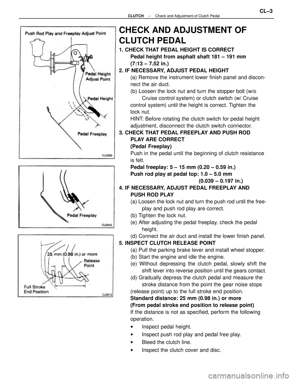
CHECK AND ADJUSTMENT OF
CLUTCH PEDAL
1. CHECK THAT PEDAL HEIGHT IS CORRECT
Pedal height from asphalt shaft 181 ± 191 mm
(7:13 ± 7.52 in.)
2. IF NECESSARY, ADJUST PEDAL HEIGHT
(a) Remove the instrument lower finish panel and discon-
nect the air duct.
(b) Loosen the lock nut and turn the stopper bolt (w/o
Cruise control system) or clutch switch (w/ Cruise
control system) until the height is correct. Tighten the
lock nut.
HINT: Before rotating the clutch switch for pedal height
adjustment, disconnect the clutch switch connector.
3. CHECK THAT PEDAL FREEPLAY AND PUSH ROD
PLAY ARE CORRECT
(Pedal Freeplay)
Push in the pedal until the beginning of clutch resistance
is felt.
Pedal freeplay: 5 ± 15 mm (0.20 ± 0.59 in.)
Push rod play at pedal top: 1.0 ± 5.0 mm
(0.039 ± 0.197 in.)
4. IF NECESSARY, ADJUST PEDAL FREEPLAY AND
PUSH ROD PLAY
(a) Loosen the lock nut and turn the push rod until the free-
play and push rod play are correct.
(b) Tighten the lock nut.
(e) After adjusting the pedal freeplay, check the pedal
height.
(d) Connect the air duct and install the lower finish panel.
5. INSPECT CLUTCH RELEASE POINT
(a) Pull the parking brake lever and install wheel stopper.
(b) Start the engine and idle the engine.
(e) Without depressing the clutch pedal, slowly shift the
shift lever into reverse position until the gears contact.
(d) Gradually depress the clutch pedal and measure the
stroke distance from the point the gear noise stops
(release point) up to the full stroke end position.
Standard distance: 25 mm (0.98 in.) or more
(From pedal stroke end position to release point)
If the distance is not as specified, perform the following
operation.
wInspect pedal height.
wInspect push rod play and pedal free play.
wBleed the clutch line.
wInspect the clutch cover and disc.
± CLUTCHCheck and Adjustment of Clutch PedalCL±3
Page 1011 of 2389
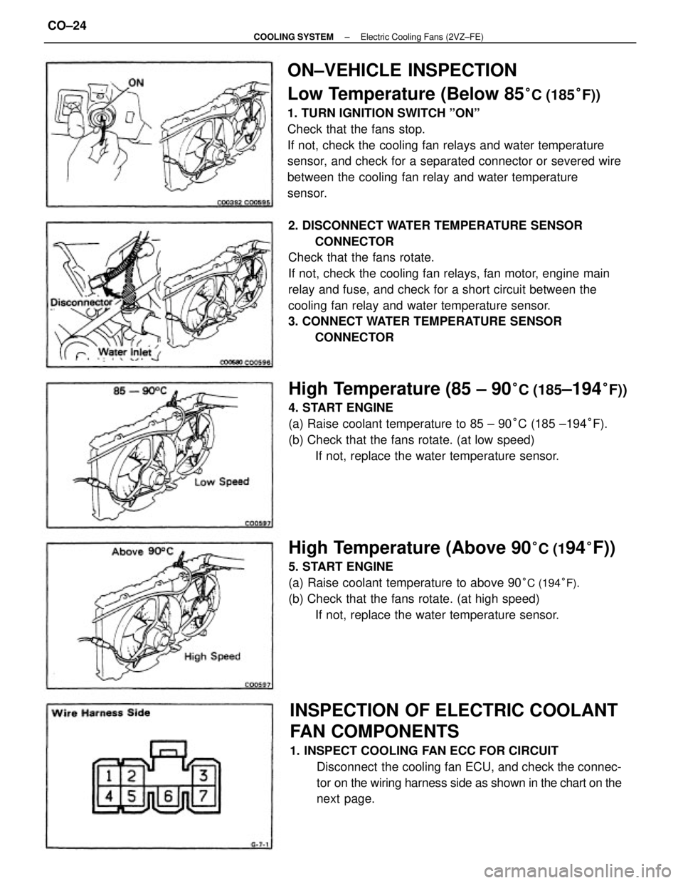
ON±VEHICLE INSPECTION
Low Temperature (Below 85
°C (185°F))
1. TURN IGNITION SWITCH ºONº
Check that the fans stop.
If not, check the cooling fan relays and water temperature
sensor, and check for a separated connector or severed wire
between the cooling fan relay and water temperature
sensor.
2. DISCONNECT WATER TEMPERATURE SENSOR
CONNECTOR
Check that the fans rotate.
If not, check the cooling fan relays, fan motor, engine main
relay and fuse, and check for a short circuit between the
cooling fan relay and water temperature sensor.
3. CONNECT WATER TEMPERATURE SENSOR
CONNECTOR
INSPECTION OF ELECTRIC COOLANT
FAN COMPONENTS
1. INSPECT COOLING FAN ECC FOR CIRCUIT
Disconnect the cooling fan ECU, and check the connec-
tor on the wiring harness side as shown in the chart on the
next page.
High Temperature (85 ± 90°C (185±194°F))
4. START ENGINE
(a) Raise coolant temperature to 85 ± 90°C (185 ±194°F).
(b) Check that the fans rotate. (at low speed)
If not, replace the water temperature sensor.
High Temperature (Above 90°C (194°F))
5. START ENGINE
(a) Raise coolant temperature to above 90
°C (194°F).
(b) Check that the fans rotate. (at high speed)
If not, replace the water temperature sensor.
± COOLING SYSTEMElectric Cooling Fans (2VZ±FE)CO±24
Page 1030 of 2389
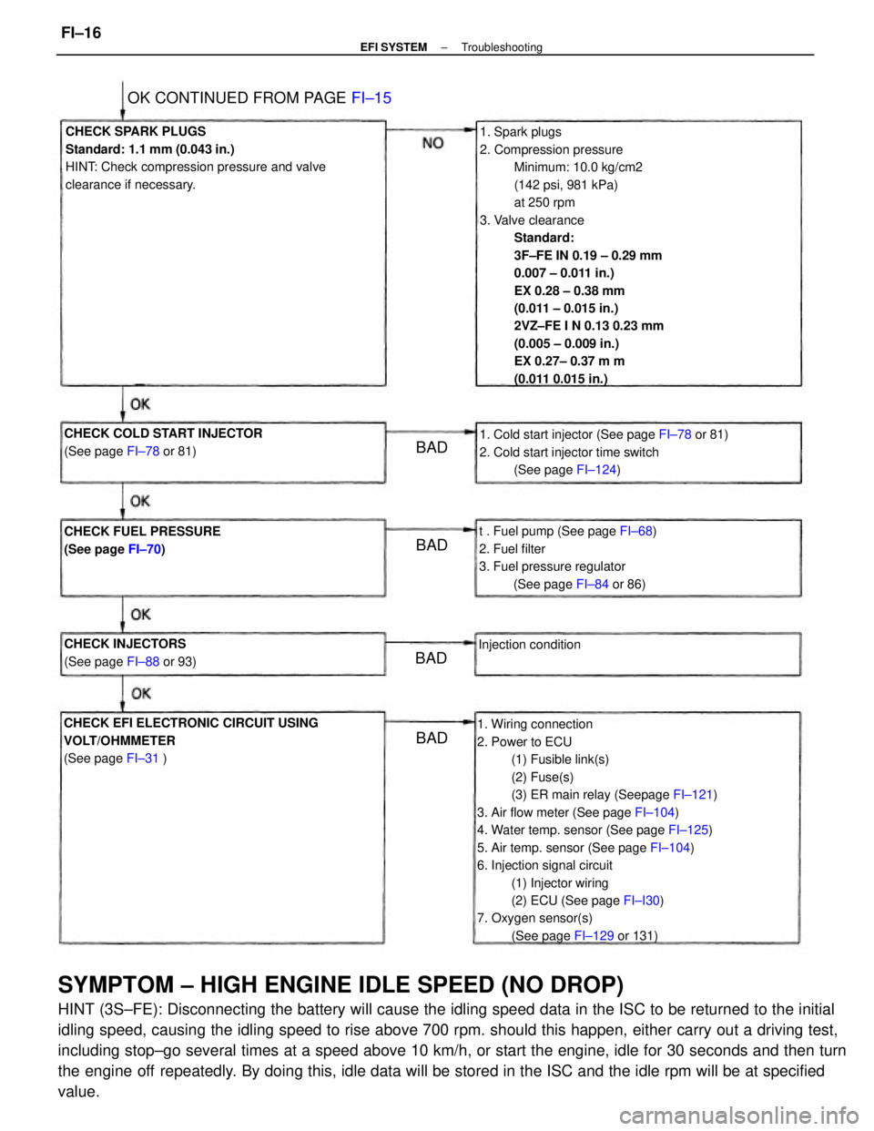
SYMPTOM ± HIGH ENGINE IDLE SPEED (NO DROP)
HINT (3S±FE): Disconnecting the battery will cause the idling speed data in the ISC to be returned to the initial
idling speed, causing the idling speed to rise above 700 rpm. should this happen, either carry out a driving test,
including stop±go several times at a speed above 10 km/h, or start the engine, idle for 30 seconds and then turn
the engine off repeatedly. By doing this, idle data will be stored in the ISC and the idle rpm will be at specified
value.
1. Spark plugs
2. Compression pressure
Minimum: 10.0 kg/cm2
(142 psi, 981 kPa)
at 250 rpm
3. Valve clearance
Standard:
3F±FE IN 0.19 ± 0.29 mm
0.007 ± 0.011 in.)
EX 0.28 ± 0.38 mm
(0.011 ± 0.015 in.)
2VZ±FE I N 0.13 0.23 mm
(0.005 ± 0.009 in.)
EX 0.27± 0.37 m m
(0.011 0.015 in.)
1. Wiring connection
2. Power to ECU
(1) Fusible link(s)
(2) Fuse(s)
(3) ER main relay (Seepage FI±121)
3. Air flow meter (See page FI±104)
4. Water temp. sensor (See page FI±125)
5. Air temp. sensor (See page FI±104)
6. Injection signal circuit
(1) Injector wiring
(2) ECU (See page FI±I30)
7. Oxygen sensor(s)
(See page FI±129 or 131) CHECK SPARK PLUGS
Standard: 1.1 mm (0.043 in.)
HINT: Check compression pressure and valve
clearance if necessary.
CHECK EFI ELECTRONIC CIRCUIT USING
VOLT/OHMMETER
(See page FI±31 )1. Cold start injector (See page FI±78 or 81)
2. Cold start injector time switch
(See page FI±124)
t . Fuel pump (See page FI±68)
2. Fuel filter
3. Fuel pressure regulator
(See page FI±84 or 86) CHECK COLD START INJECTOR
(See page FI±78 or 81)
CHECK FUEL PRESSURE
(See page FI±70)
OK CONTINUED FROM PAGE FI±15
CHECK INJECTORS
(See page FI±88 or 93)Injection condition
BADBAD
BAD
BAD
± EFI SYSTEMTroubleshootingFI±16
Page 1040 of 2389
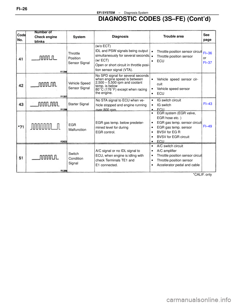
(w/o ECT)
IDL and PSW signals being output
simultaneously for several seconds.
(w/ ECT)
Open or short circuit in throttle posi-
tion sensor signal (VTA).
wEGR system (EGR valve,
EGR hose etc. )
wEGR gas temp. sensor circuit
wEGR gas temp. sensor
wBVSV for EG R
wBVSV for EGR circuit
wECU
wA/C switch circuit
wA/C amplifier
wThrottle position sensor circuit
wThrottle position sensor
wAccelerator pedal and cable No SPD signal for several seconds
when engine speed is between
2,500 ± 5,500 rpm and coolant
temp. is below
80°C (176°F) except when racing
the engine.
DIAGNOSTIC CODES (3S±FE) (Cont'd)
A/C signal or no IDL signal to
ECU, when engine is idling with
check Terminals TE1 and
E1 connected.wThrottle position sensor circuit
wThrottle position sensor
wECU
wVehicle speed sensor cir-
cuit
wVehicle speed sensor
wECU
EGR gas temp. below predeter-
mined level for during
EGR control.No STA signal to ECU when ve-
hicle stopped and engine running
over 800 rpm.wIG switch circuit
wIG switch
wECU Number of
Check engine
blinks
Throttle
Position
Sensor Signal
Switch
Condition
Signal Vehicle Speed
Sensor Signal
EGR
Malfunction Starter Signal
*CALIF. only Trouble area
FI±36
or
FI±37 DiagnosisSee
page Code
No.System
FI±49FI±43
± EFI SYSTEMDiagnosis SystemFI±26
Page 1050 of 2389
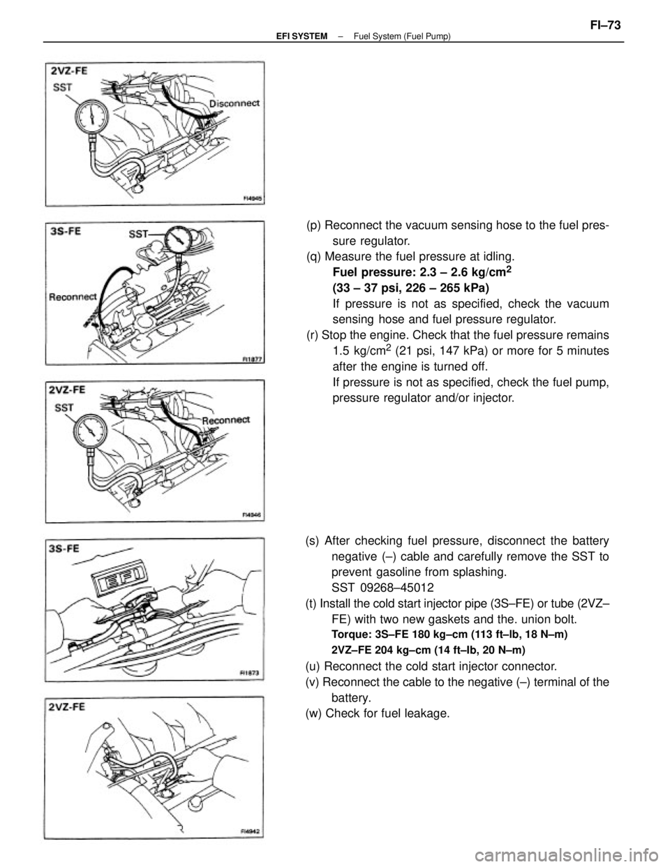
(s) After checking fuel pressure, disconnect the battery
negative (±) cable and carefully remove the SST to
prevent gasoline from splashing.
SST 09268±45012
(t) Install the cold start injector pipe (3S±FE) or tube (2VZ±
FE) with two new gaskets and the. union bolt.
Torque: 3S±FE 180 kg±cm (113 ft±lb, 18 N±m)
2VZ±FE 204 kg±cm (14 ft±Ib, 20 N±m)
(u) Reconnect the cold start injector connector.
(v) Reconnect the cable to the negative (±) terminal of the
battery.
(w) Check for fuel leakage.(p) Reconnect the vacuum sensing hose to the fuel pres-
sure regulator.
(q) Measure the fuel pressure at idling.
Fuel pressure: 2.3 ± 2.6 kg/cm
2
(33 ± 37 psi, 226 ± 265 kPa)
If pressure is not as specified, check the vacuum
sensing hose and fuel pressure regulator.
(r) Stop the engine. Check that the fuel pressure remains
1.5 kg/cm
2 (21 psi, 147 kPa) or more for 5 minutes
after the engine is turned off.
If pressure is not as specified, check the fuel pump,
pressure regulator and/or injector.
± EFI SYSTEMFuel System (Fuel Pump)FI±73
Page 1056 of 2389
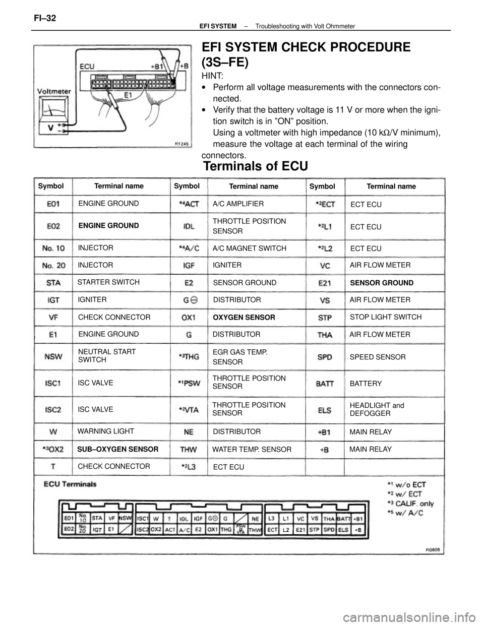
EFI SYSTEM CHECK PROCEDURE
(3S±FE)
HINT:
wPerform all voltage measurements with the connectors con-
nected.
wVerify that the battery voltage is 11 V or more when the igni-
tion switch is in ºONº position.
Using a voltmeter with high impedance (10 kW/V minimum),
measure the voltage at each terminal of the wiring
connectors.
THROTTLE POSITION
SENSORTHROTTLE POSITION
SENSOR
THROTTLE POSITION
SENSOR
Terminals of ECU
NEUTRAL START
SWITCH
HEADLIGHT and
DEFOGGER EGR GAS TEMP.
SENSOR
WATER TEMP. SENSOR SUB±OXYGEN SENSORA/C MAGNET SWITCH
STOP LIGHT SWITCH
CHECK CONNECTORCHECK CONNECTORAIR FLOW METER
AIR FLOW METER
AIR FLOW METER STARTER SWITCH
SENSOR GROUND SENSOR GROUND ENGINE GROUND
ENGINE GROUND ENGINE GROUND
OXYGEN SENSOR
WARNING LIGHTA/C AMPLIFIER
SPEED SENSORTerminal name Terminal name Terminal name
DISTRIBUTORDISTRIBUTOR
DISTRIBUTOR
MAIN RELAYMAIN RELAY ISC VALVE
ISC VALVE INJECTORINJECTOR Symbol
BATTERY Symbol
Symbol
IGNITERECT ECUECT ECU
ECT ECU
IGNITER
ECT ECU
± EFI SYSTEMTroubleshooting with Volt OhmmeterFI±32
Page 1120 of 2389
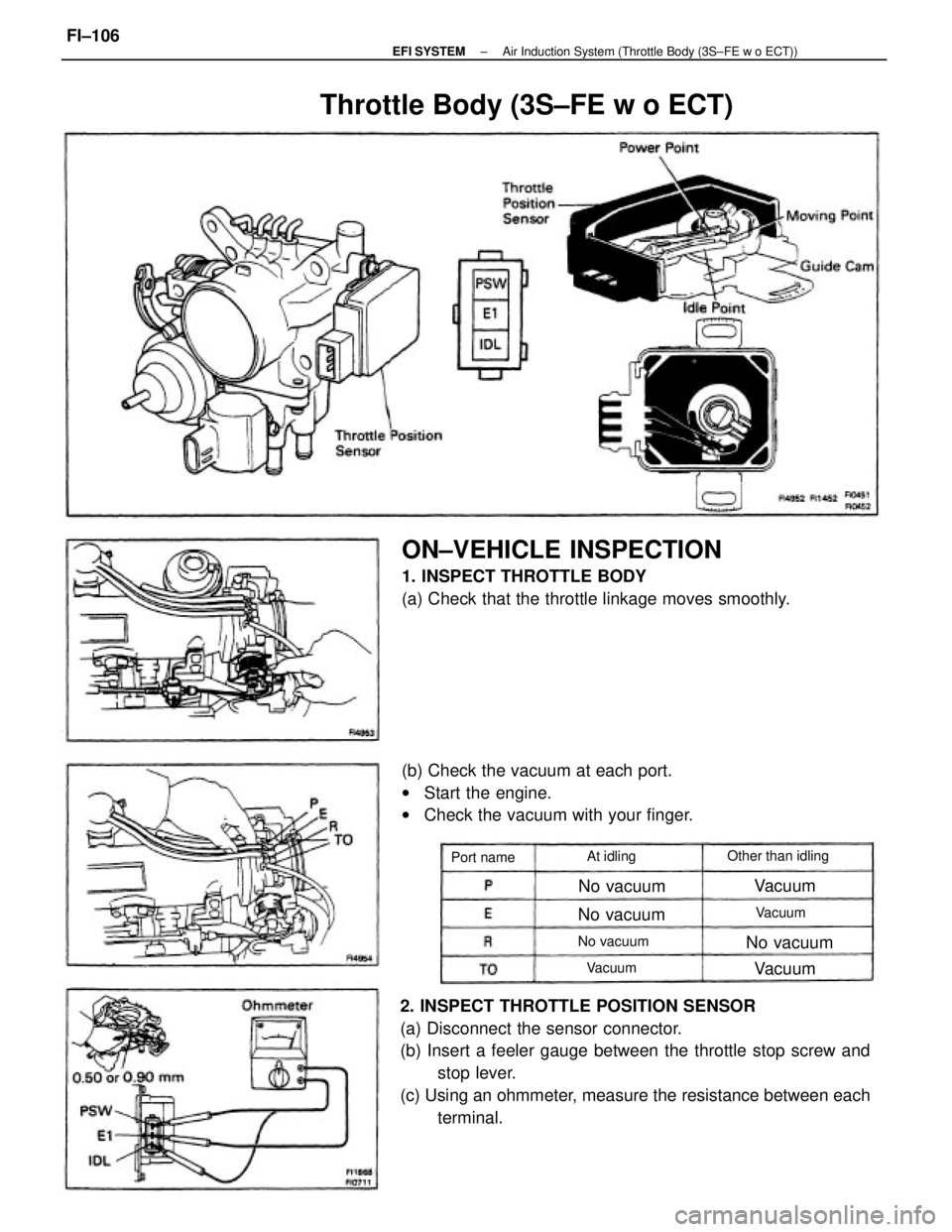
2. INSPECT THROTTLE POSITION SENSOR
(a) Disconnect the sensor connector.
(b) Insert a feeler gauge between the throttle stop screw and
stop lever.
(c) Using an ohmmeter, measure the resistance between each
terminal.
ON±VEHICLE INSPECTION
1. INSPECT THROTTLE BODY
(a) Check that the throttle linkage moves smoothly.
(b) Check the vacuum at each port.
wStart the engine.
wCheck the vacuum with your finger.
Throttle Body (3S±FE w o ECT)
Other than idling
No vacuum
No vacuum No vacuum
No vacuum Port nameAt idling
Vacuum
Vacuum
VacuumVacuum
± EFI SYSTEMAir Induction System (Throttle Body (3S±FE w o ECT))FI±106
Page 1126 of 2389
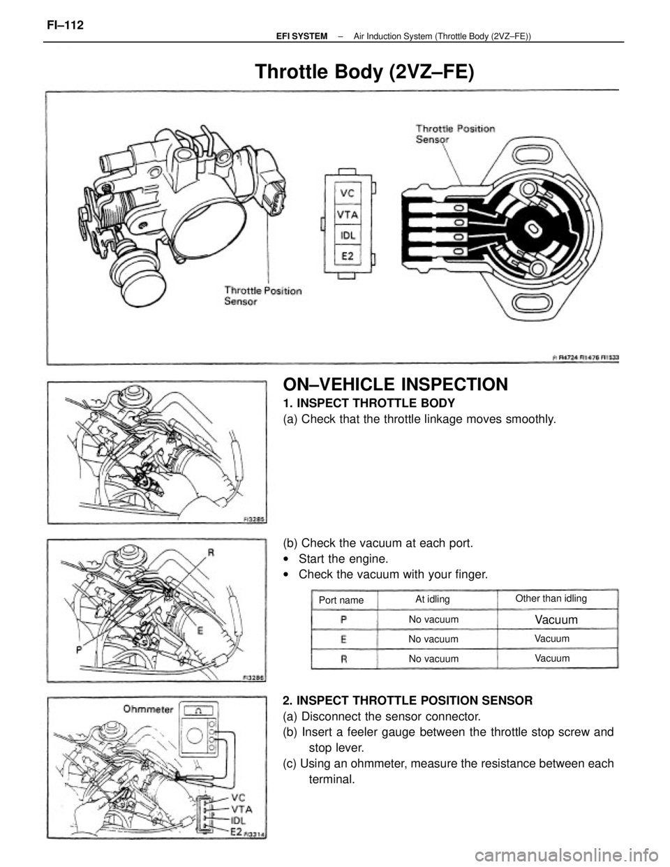
2. INSPECT THROTTLE POSITION SENSOR
(a) Disconnect the sensor connector.
(b) Insert a feeler gauge between the throttle stop screw and
stop lever.
(c) Using an ohmmeter, measure the resistance between each
terminal.
ON±VEHICLE INSPECTION
1. INSPECT THROTTLE BODY
(a) Check that the throttle linkage moves smoothly.
(b) Check the vacuum at each port.
wStart the engine.
wCheck the vacuum with your finger.
Throttle Body (2VZ±FE)
Other than idling
No vacuum No vacuum
No vacuum Port nameAt idling
Vacuum
Vacuum
Vacuum
± EFI SYSTEMAir Induction System (Throttle Body (2VZ±FE))FI±112
Page 1196 of 2389
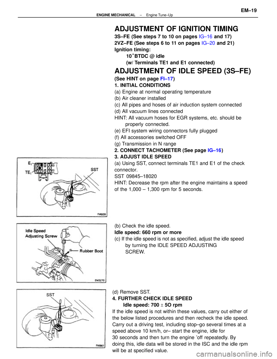
ADJUSTMENT OF IGNITION TIMING
3S±FE (See steps 7 to 10 on pages IG±16 and 17)
2VZ±FE (See steps 6 to 11 on pages IG±20 and 21)
Ignition timing:
10°BTDC @ idle
(w/ Terminals TE1 and E1 connected)
ADJUSTMENT OF IDLE SPEED (3S±FE)
(See HINT on page FI±17)
1. INITIAL CONDITIONS
(a) Engine at normal operating temperature
(b) Air cleaner installed
(c) All pipes and hoses of air induction system connected
(d) All vacuum lines connected
HINT: All vacuum hoses for EGR systems, etc. should be
properly connected.
(e) EFI system wiring connectors fully plugged
(f) All accessories switched OFF
(g) Transmission in N range
2. CONNECT TACHOMETER (See page IG±16)
3. ADJUST IDLE SPEED
(a) Using SST, connect terminals TE1 and E1 of the check
connector.
SST 09845±18020
HINT: Decrease the rpm after the engine maintains a speed
of the 1,000 ± 1,300 rpm for 5 seconds.
(d) Remove SST.
4. FURTHER CHECK IDLE SPEED
Idle speed: 700
+ 5O rpm
If the idle speed is not within these values, carry out either of
the below listed procedures and then recheck the idle speed.
Carry out a driving test, including stop±go several times at a
speed above 10 km/h, or± start the engine, idle for
30 seconds and then turn the engine 'off repeatedly. By
doing this, idle data will be stored in the ISC and the idle rpm
will be at specified value.(b) Check the idle speed.
Idle speed: 660 rpm or more
(c) If the idle speed is not as specified, adjust the idle speed
by turning the IDLE SPEED ADJUSTING
SCREW.
± ENGINE MECHANICALEngine Tune±UpEM±19
Page 1199 of 2389
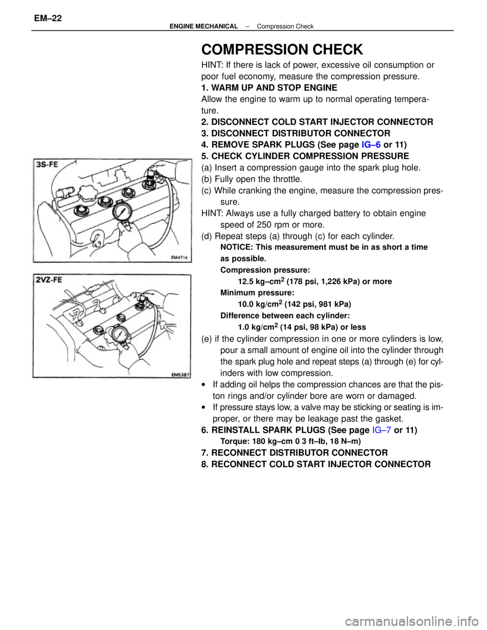
COMPRESSION CHECK
HINT: If there is lack of power, excessive oil consumption or
poor fuel economy, measure the compression pressure.
1. WARM UP AND STOP ENGINE
Allow the engine to warm up to normal operating tempera-
ture.
2. DISCONNECT COLD START INJECTOR CONNECTOR
3. DISCONNECT DISTRIBUTOR CONNECTOR
4. REMOVE SPARK PLUGS (See page IG±6 or 11)
5. CHECK CYLINDER COMPRESSION PRESSURE
(a) Insert a compression gauge into the spark plug hole.
(b) Fully open the throttle.
(c) While cranking the engine, measure the compression pres-
sure.
HINT: Always use a fully charged battery to obtain engine
speed of 250 rpm or more.
(d) Repeat steps (a) through (c) for each cylinder.
NOTICE: This measurement must be in as short a time
as possible.
Compression pressure:
12.5 kg±cm
2 (178 psi, 1,226 kPa) or more
Minimum pressure:
10.0 kg/cm
2 (142 psi, 981 kPa)
Difference between each cylinder:
1.0 kg/cm
2 (14 psi, 98 kPa) or less
(e) if the cylinder compression in one or more cylinders is low,
pour a small amount of engine oil into the cylinder through
the spark plug hole and repeat steps (a) through (e) for cyl-
inders with low compression.
wIf adding oil helps the compression chances are that the pis-
ton rings and/or cylinder bore are worn or damaged.
wIf pressure stays low, a valve may be sticking or seating is im-
proper, or there may be leakage past the gasket.
6. REINSTALL SPARK PLUGS (See page IG±7 or 11)
Torque: 180 kg±cm 0 3 ft±Ib, 18 N±m)
7. RECONNECT DISTRIBUTOR CONNECTOR
8. RECONNECT COLD START INJECTOR CONNECTOR
± ENGINE MECHANICALCompression CheckEM±22