stop start TOYOTA CAMRY V20 1986 Service Information
[x] Cancel search | Manufacturer: TOYOTA, Model Year: 1986, Model line: CAMRY V20, Model: TOYOTA CAMRY V20 1986Pages: 2389, PDF Size: 84.44 MB
Page 1869 of 2389
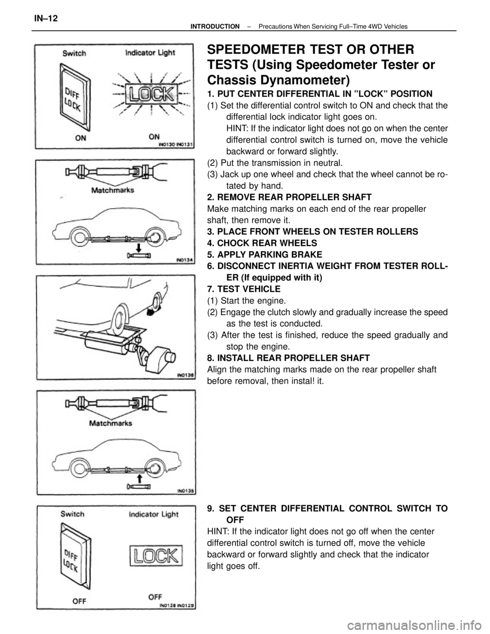
SPEEDOMETER TEST OR OTHER
TESTS (Using Speedometer Tester or
Chassis Dynamometer)
1. PUT CENTER DIFFERENTIAL IN ºLOCKº POSITION
(1) Set the differential control switch to ON and check that the
differential lock indicator light goes on.
HINT: If the indicator light does not go on when the center
differential control switch is turned on, move the vehicle
backward or forward slightly.
(2) Put the transmission in neutral.
(3) Jack up one wheel and check that the wheel cannot be ro-
tated by hand.
2. REMOVE REAR PROPELLER SHAFT
Make matching marks on each end of the rear propeller
shaft, then remove it.
3. PLACE FRONT WHEELS ON TESTER ROLLERS
4. CHOCK REAR WHEELS
5. APPLY PARKING BRAKE
6. DISCONNECT INERTIA WEIGHT FROM TESTER ROLL-
ER (If equipped with it)
7. TEST VEHICLE
(1) Start the engine.
(2) Engage the clutch slowly and gradually increase the speed
as the test is conducted.
(3) After the test is finished, reduce the speed gradually and
stop the engine.
8. INSTALL REAR PROPELLER SHAFT
Align the matching marks made on the rear propeller shaft
before removal, then instal! it.
9. SET CENTER DIFFERENTIAL CONTROL SWITCH TO
OFF
HINT: If the indicator light does not go off when the center
differential control switch is turned off, move the vehicle
backward or forward slightly and check that the indicator
light goes off.
± INTRODUCTIONPrecautions When Servicing Full±Time 4WD VehiclesIN±12
Page 1878 of 2389
![TOYOTA CAMRY V20 1986 Service Information SPEEDOMETER TEST OR OTHER TESTS
[Using Speedometer Tester or Chassis Dynamometer]
1. SET CENTER DIFFERENTIAL CONTROL SWITCH TO
OFF
(1) Check that the center differential control indicator light
goes TOYOTA CAMRY V20 1986 Service Information SPEEDOMETER TEST OR OTHER TESTS
[Using Speedometer Tester or Chassis Dynamometer]
1. SET CENTER DIFFERENTIAL CONTROL SWITCH TO
OFF
(1) Check that the center differential control indicator light
goes](/img/14/57449/w960_57449-1877.png)
SPEEDOMETER TEST OR OTHER TESTS
[Using Speedometer Tester or Chassis Dynamometer]
1. SET CENTER DIFFERENTIAL CONTROL SWITCH TO
OFF
(1) Check that the center differential control indicator light
goes oft.
(2) Further check that the operation of the hydraulic
multiplate clutch control of the center differential is in
OFF condition.
(See page IN±15)
2. MOVE MODE SELECT LEVER ON TRANSAXLE TO ºLOCKº
MODE AND LOCK IT SECURELY WITH BOLT (See page
IN±16)
3. CONFIRM MODE SELECTION
(See page IN±17)
8. DISCONNECT INERTIA WEIGHT FROM TESTER ROLL-
ER (If equipped with it)
9. TEST VEHICLE
(1) Start the engine.
(2) Put the transmission in D range, then gradually in-
crease the speed as the test in conducted.
(3) After the test is finished, reduce the speed gradually
and stop the engine. 4. REMOVE REAR PROPELLER SHAFT
Make matching marks on each end of the rear propeller
shaft, then remove it.
5. PLACE FRONT WHEELS ON TESTER ROLLERS
6. CHOCK REAR WHEELS
7. APPLY PARKING BRAKE
10. AFTER FINISHING TEST, INSTALL REAR PROPELLER
SHAFT
Align the matching marks made on the rear propeller shaft
before removal, then install it.
± INTRODUCTIONPrecautions When Servicing Full±Time 4WD VehiclesIN±21
Page 2222 of 2389
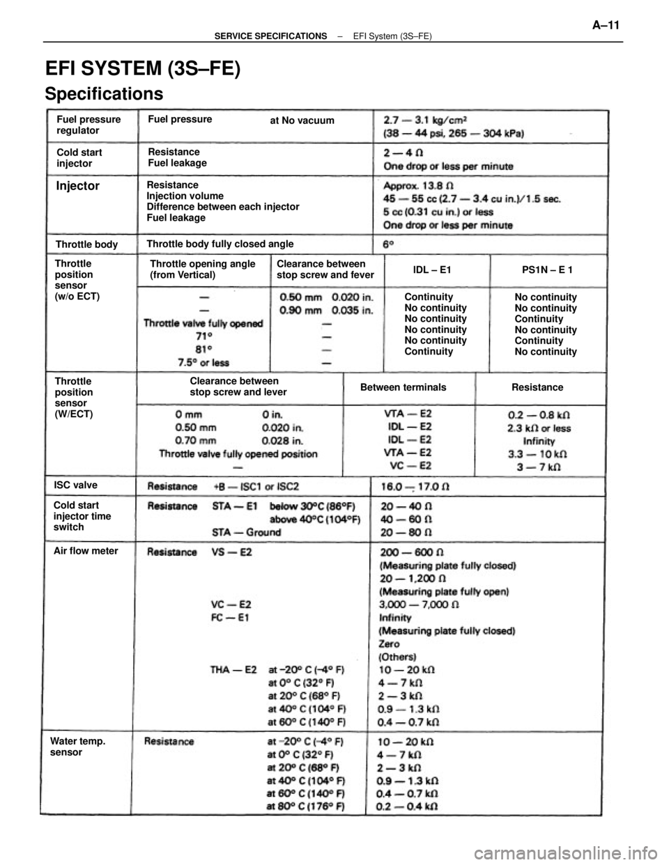
Resistance
Injection volume
Difference between each injector
Fuel leakage
EFI SYSTEM (3S±FE)
Specifications
No continuity
No continuity
Continuity
No continuity
Continuity
No continuity Continuity
No continuity
No continuity
No continuity
No continuity
Continuity Throttle opening angle
(from Vertical)Clearance between
stop screw and fever
Clearance between
stop screw and lever Throttle
position
sensor
(w/o ECT)Throttle body fully closed angle
Cold start
injector time
switchThrottle
position
sensor
(W/ECT)Fuel pressure
regulator
Resistance
Fuel leakage
Water temp.
sensorBetween terminals Cold start
injector
Air flow meterFuel pressure
Throttle bodyat No vacuum
ResistancePS1N ± E 1
ISC valvelDL ± E1
Injector
± SERVICE SPECIFICATIONSEFI System (3S±FE)A±11
Page 2226 of 2389
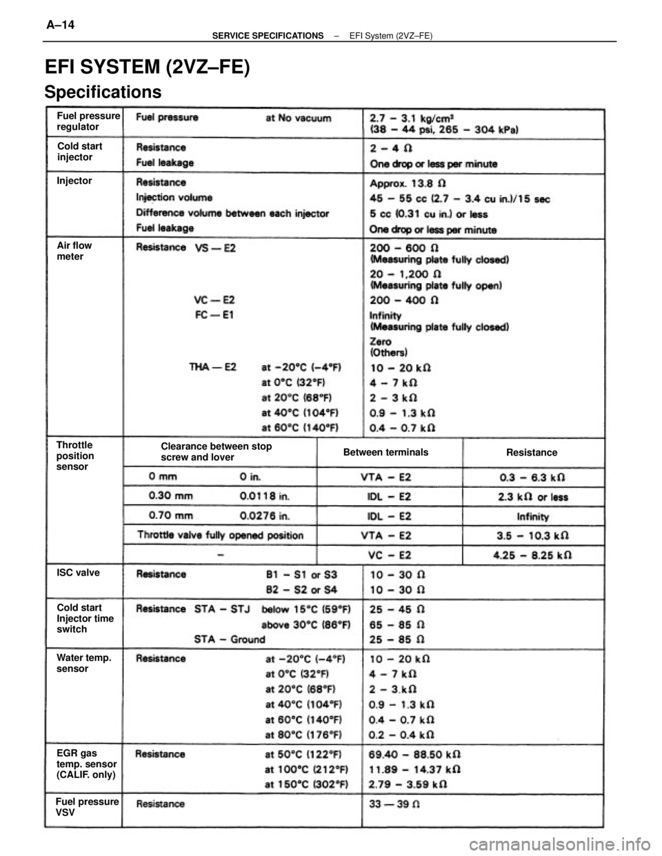
EFI SYSTEM (2VZ±FE)
Specifications
Clearance between stop
screw and lover
EGR gas
temp. sensor
(CALIF. only)Cold start
Injector time
switch Fuel pressure
regulator
Fuel pressure
VSVWater temp.
sensor Throttle
position
sensorBetween terminals Cold start
injector
Air flow
meter
Resistance
ISC valve Injector
± SERVICE SPECIFICATIONSEFI System (2VZ±FE)A±14
Page 2316 of 2389
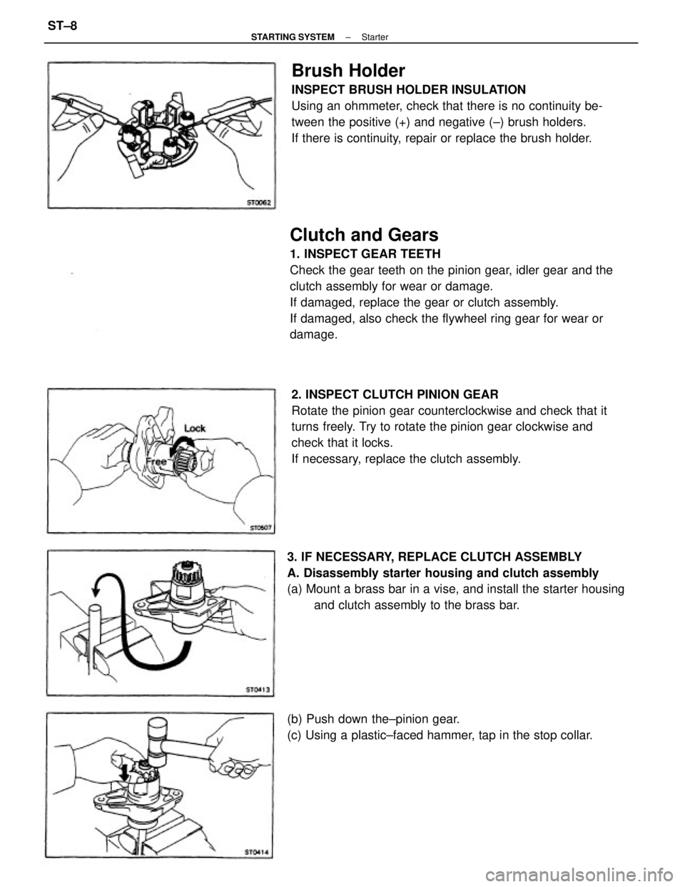
Clutch and Gears
1. INSPECT GEAR TEETH
Check the gear teeth on the pinion gear, idler gear and the
clutch assembly for wear or damage.
If damaged, replace the gear or clutch assembly.
If damaged, also check the flywheel ring gear for wear or
damage.
2. INSPECT CLUTCH PINION GEAR
Rotate the pinion gear counterclockwise and check that it
turns freely. Try to rotate the pinion gear clockwise and
check that it locks.
If necessary, replace the clutch assembly.
Brush Holder
INSPECT BRUSH HOLDER INSULATION
Using an ohmmeter, check that there is no continuity be-
tween the positive (+) and negative (±) brush holders.
If there is continuity, repair or replace the brush holder.
3. IF NECESSARY, REPLACE CLUTCH ASSEMBLY
A. Disassembly starter housing and clutch assembly
(a) Mount a brass bar in a vise, and install the starter housing
and clutch assembly to the brass bar.
(b) Push down the±pinion gear.
(c) Using a plastic±faced hammer, tap in the stop collar.
± STARTING SYSTEMStarterST±8
Page 2317 of 2389
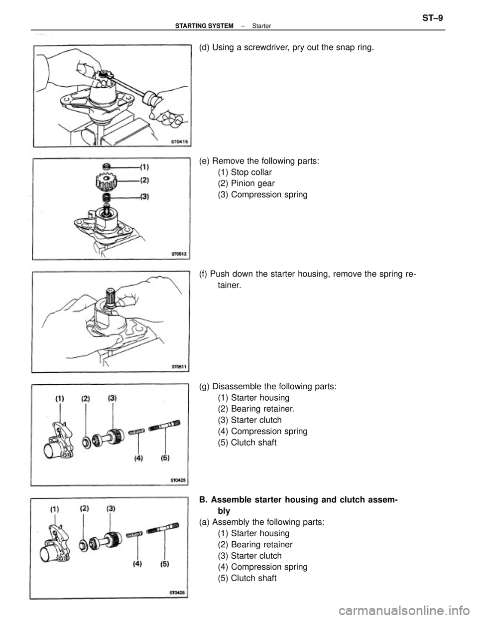
B. Assemble starter housing and clutch assem-
bly
(a) Assembly the following parts:
(1) Starter housing
(2) Bearing retainer
(3) Starter clutch
(4) Compression spring
(5) Clutch shaft (g) Disassemble the following parts:
(1) Starter housing
(2) Bearing retainer.
(3) Starter clutch
(4) Compression spring
(5) Clutch shaft (e) Remove the following parts:
(1) Stop collar
(2) Pinion gear
(3) Compression spring
(f) Push down the starter housing, remove the spring re-
tainer. (d) Using a screwdriver, pry out the snap ring.
± STARTING SYSTEMStarterST±9
Page 2318 of 2389
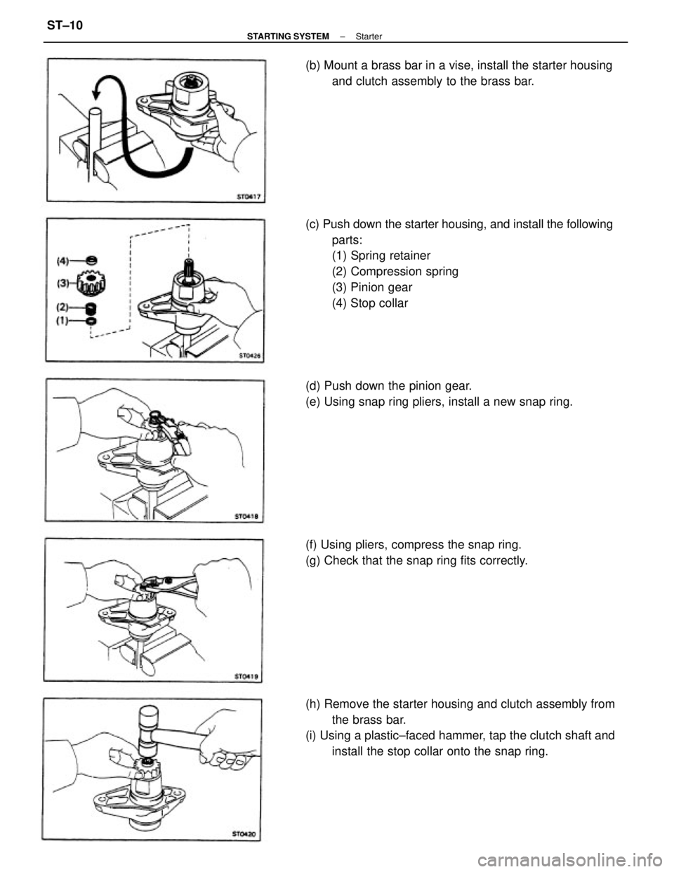
(c) Push down the starter housing, and install the following
parts:
(1) Spring retainer
(2) Compression spring
(3) Pinion gear
(4) Stop collar
(h) Remove the starter housing and clutch assembly from
the brass bar.
(i) Using a plastic±faced hammer, tap the clutch shaft and
install the stop collar onto the snap ring. (d) Push down the pinion gear.
(e) Using snap ring pliers, install a new snap ring. (b) Mount a brass bar in a vise, install the starter housing
and clutch assembly to the brass bar.
(f) Using pliers, compress the snap ring.
(g) Check that the snap ring fits correctly.
± STARTING SYSTEMStarterST±10
Page 2349 of 2389
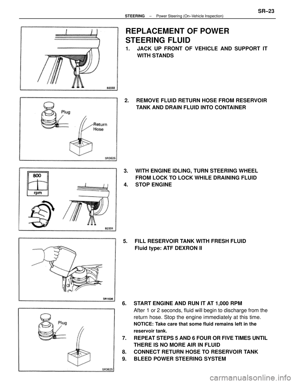
6. START ENGINE AND RUN IT AT 1,000 RPM
After 1 or 2 seconds, fluid will begin to discharge from the
return hose. Stop the engine immediately at this time.
NOTICE: Take care that some fluid remains left in the
reservoir tank.
7. REPEAT STEPS 5 AND 6 FOUR OR FIVE TIMES UNTIL
THERE IS NO MORE AIR IN FLUID
8. CONNECT RETURN HOSE TO RESERVOIR TANK
9. BLEED POWER STEERING SYSTEM
REPLACEMENT OF POWER
STEERING FLUID
1. JACK UP FRONT OF VEHICLE AND SUPPORT IT
WITH STANDS
3. WITH ENGINE IDLING, TURN STEERING WHEEL
FROM LOCK TO LOCK WHILE DRAINING FLUID
4. STOP ENGINE2. REMOVE FLUID RETURN HOSE FROM RESERVOIR
TANK AND DRAIN FLUID INTO CONTAINER
5. FILL RESERVOIR TANK WITH FRESH FLUID
Fluid type: ATF DEXRON II
± STEERINGPower Steering (On±Vehicle Inspection)SR±23
Page 2350 of 2389
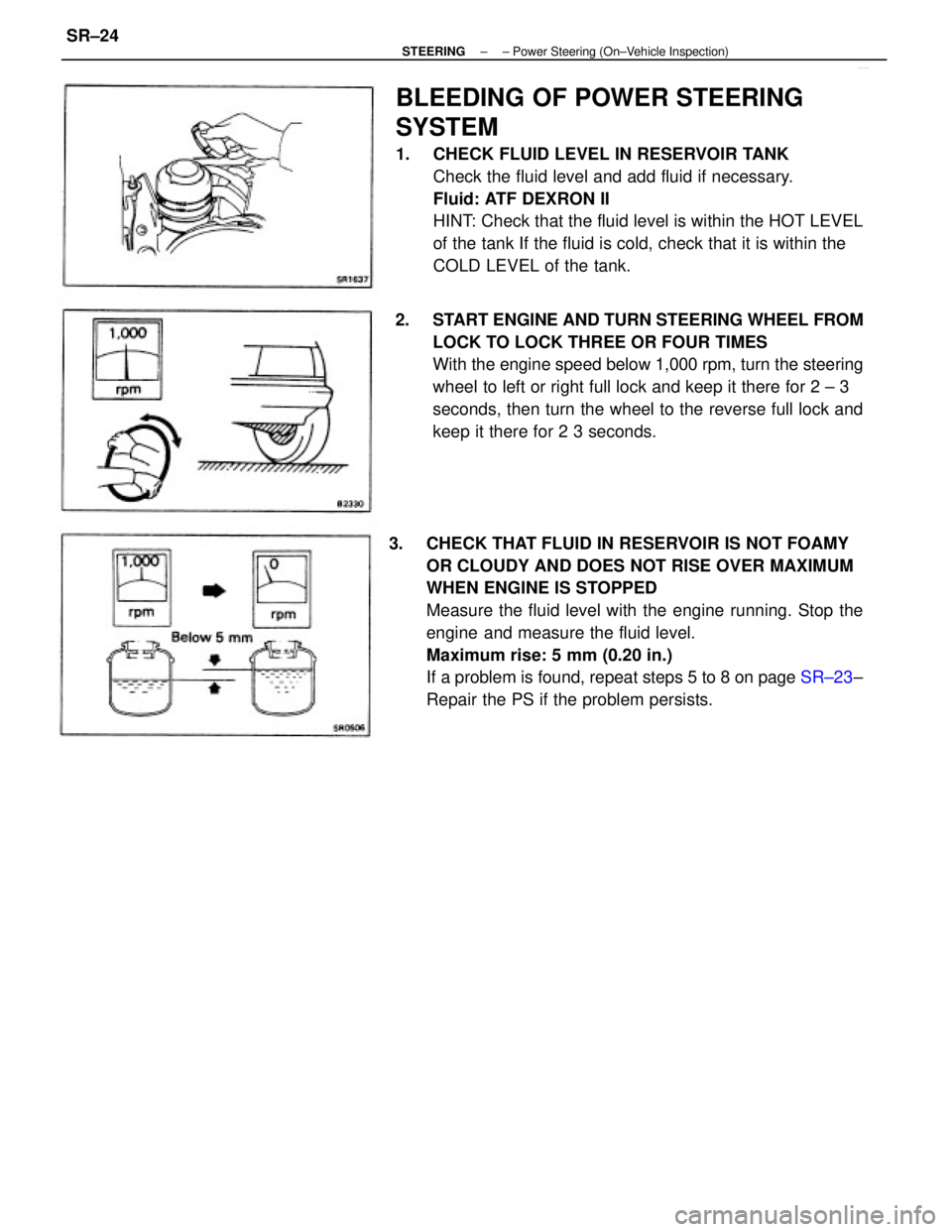
3. CHECK THAT FLUID IN RESERVOIR IS NOT FOAMY
OR CLOUDY AND DOES NOT RISE OVER MAXIMUM
WHEN ENGINE IS STOPPED
Measure the fluid level with the engine running. Stop the
engine and measure the fluid level.
Maximum rise: 5 mm (0.20 in.)
If a problem is found, repeat steps 5 to 8 on page SR±23±
Repair the PS if the problem persists.
BLEEDING OF POWER STEERING
SYSTEM
1. CHECK FLUID LEVEL IN RESERVOIR TANK
Check the fluid level and add fluid if necessary.
Fluid: ATF DEXRON II
HINT: Check that the fluid level is within the HOT LEVEL
of the tank If the fluid is cold, check that it is within the
COLD LEVEL of the tank.
2. START ENGINE AND TURN STEERING WHEEL FROM
LOCK TO LOCK THREE OR FOUR TIMES
With the engine speed below 1,000 rpm, turn the steering
wheel to left or right full lock and keep it there for 2 ± 3
seconds, then turn the wheel to the reverse full lock and
keep it there for 2 3 seconds.
± STEERING± Power Steering (On±Vehicle Inspection)SR±24