panel TOYOTA CAMRY V20 1986 Service Information
[x] Cancel search | Manufacturer: TOYOTA, Model Year: 1986, Model line: CAMRY V20, Model: TOYOTA CAMRY V20 1986Pages: 2389, PDF Size: 84.44 MB
Page 289 of 2389
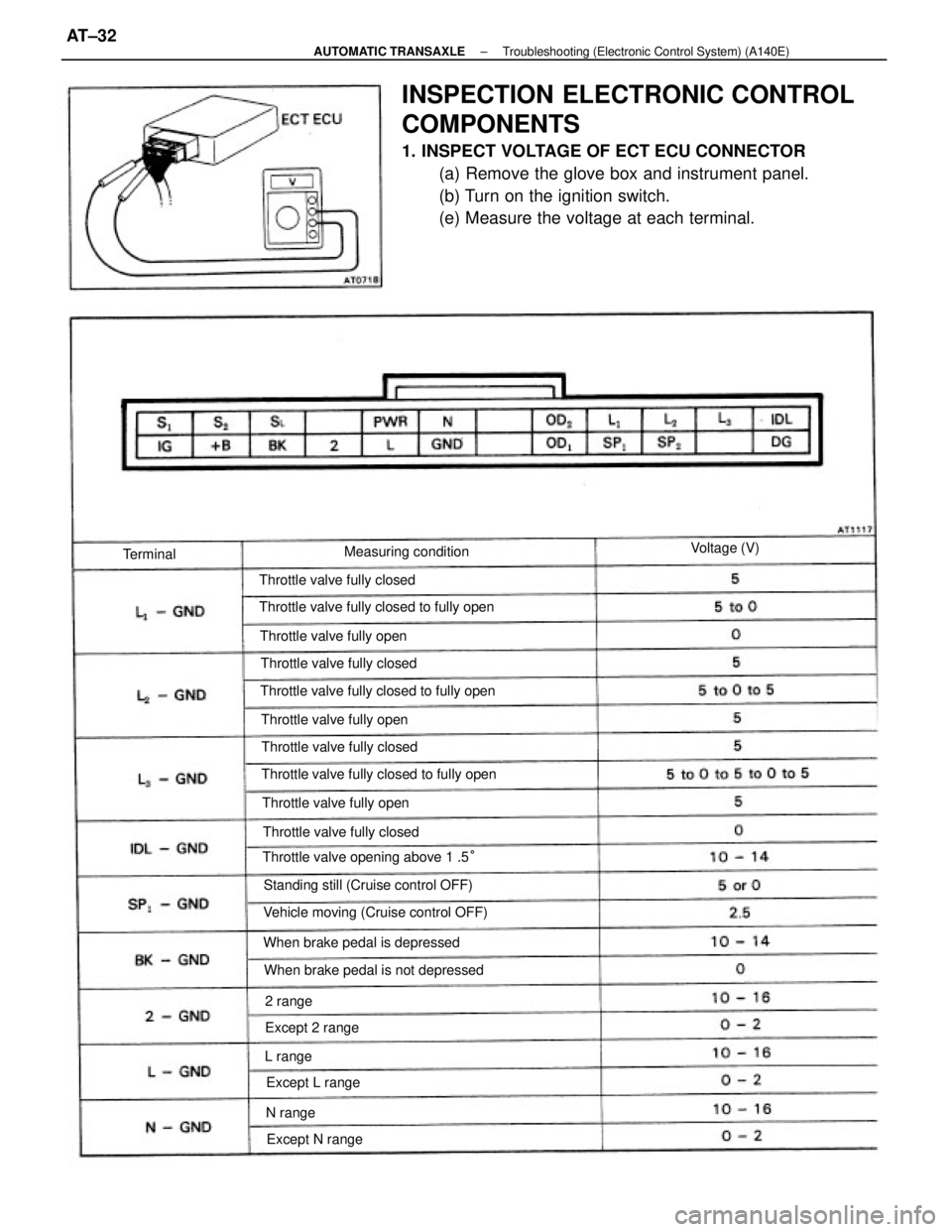
INSPECTION ELECTRONIC CONTROL
COMPONENTS
1. INSPECT VOLTAGE OF ECT ECU CONNECTOR
(a) Remove the glove box and instrument panel.
(b) Turn on the ignition switch.
(e) Measure the voltage at each terminal.
Throttle valve fully closed to fully open Throttle valve fully closed to fully open
Throttle valve fully closed to fully open
Vehicle moving (Cruise control OFF)Standing still (Cruise control OFF) Throttle valve opening above 1 .5°
When brake pedal is not depressed When brake pedal is depressed Throttle valve fully closed Throttle valve fully closed
Throttle valve fully closed
Throttle valve fully closed Throttle valve fully open Throttle valve fully open Throttle valve fully openMeasuring condition
Except L range
Except N range Except 2 rangeVoltage (V)
Terminal
N range 2 range
L range
± AUTOMATIC TRANSAXLETroubleshooting (Electronic Control System) (A140E)AT±32
Page 668 of 2389
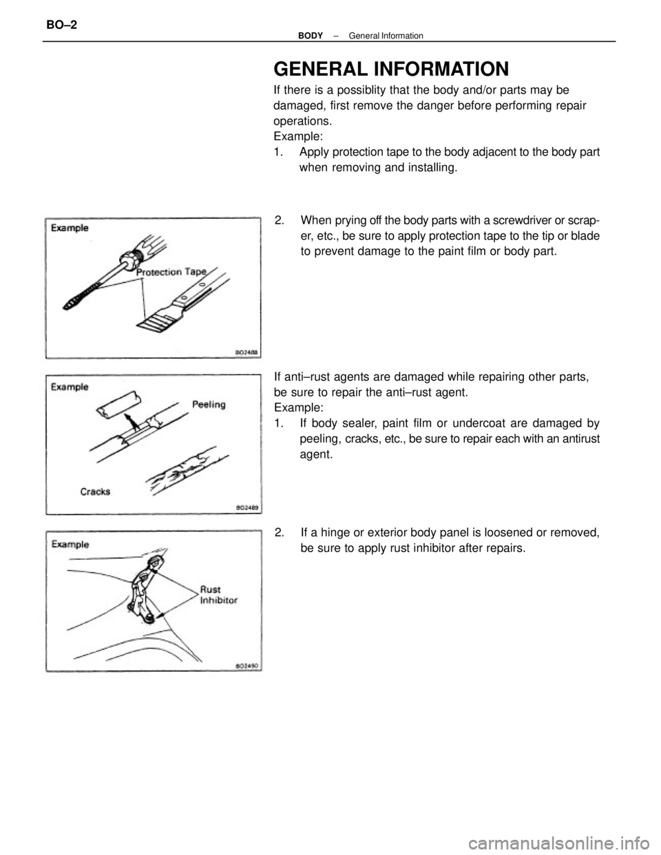
GENERAL INFORMATION
If there is a possiblity that the body and/or parts may be
damaged, first remove the danger before performing repair
operations.
Example:
1. Apply protection tape to the body adjacent to the body part
when removing and installing.
If anti±rust agents are damaged while repairing other parts,
be sure to repair the anti±rust agent.
Example:
1. If body sealer, paint film or undercoat are damaged by
peeling, cracks, etc., be sure to repair each with an antirust
agent. 2. When prying off the body parts with a screwdriver or scrap-
er, etc., be sure to apply protection tape to the tip or blade
to prevent damage to the paint film or body part.
2. If a hinge or exterior body panel is loosened or removed,
be sure to apply rust inhibitor after repairs.
± BODYGeneral InformationBO±2
Page 672 of 2389

7. REMOVE DOOR GLASS
(a) Wind the glass down into the door cavity.
(b) Remove the two glass channel mounting nuts.
8. REMOVE WINDOW REGULATOR
(a) (w/ Power Window)
Disconnect the connector.
(b) Remove the regulator mounting bolts.
(e) Remove the equalizer arm bracket mounting bolts.
10. REMOVE REAR LOWER FRAME
11. REMOVE FRONT LOWER FRAME
Remove the two bolts from the panel. (d) Remove the regulator through the service hole.
9. REMOVE DOOR GLASS RUN(c) Remove the door glass by pulling it upward.
± BODYFront DoorBO±6
Page 673 of 2389

ASSEMBLY OF FRONT DOOR
(See page BO±3)
1. BEFORE INSTALLING PARTS, COAT THEM WITH MIP
GREASE
(a) Coat the sliding surface and gears of the window
regulator with MP grease.
NOTICE: Do not apply MP grease to the spring of the win-
dow regulator.
13. REMOVE DOOR LOCK
(a) Disconnect the links from the door outside handle
and door lock cylinder.
(b) Remove the three screws and the door lock.
(c) (w/ Power Door Lock)
Remove the screw and door lock solenoid. 12. REMOVE FRONT DOOR BELT MOULDING
(a) Remove the screw.
(b) Pry loose the clips from the edge of the panel and re-
move the front door belt moulding.
14. REMOVE DOOR OUTSIDE HANDLE AND DOOR
LOCK CYLINDER
(a) Remove the two bolts and door outside handle.
(b) Remove the clip and door lock cylinder.
(b) Coat the sliding surface of the door lock with IMP
grease.
± BODYFront DoorBO±7
Page 674 of 2389

3. INSTALL DOOR LOCK
(a) (w/ Power Door Lock)
Install the door lock solenoid to the door lock with the
screw.
(b) InstalI the door lock with the three screws.
(e) Install the links to the door outside handle and door
lock cylinder. 2. INSTALL DOOR OUTSIDE HANDLE AND DOOR LOCK
CYLINDER
(a) Install the door outside handle with the two bolts.
(b) Install the door lock cylinder with the clip.
4. INSTALL FRONT DOOR BELT MOULDING
(a) Insert the claw of the clips into the upper panel hole
and push the front door belt moulding onto the panel.
(b) Install the screw.
7. INSTALL WINDOW REGULATOR
Place the regulator through the service hole and install the
five mounting bolts. 5. INSTALL FRONT LOWER FRAME
Install the front lower frame with the two bolts.
6. INSTALL REAR LOWER FRAME
± BODYFront DoorBO±8
Page 678 of 2389
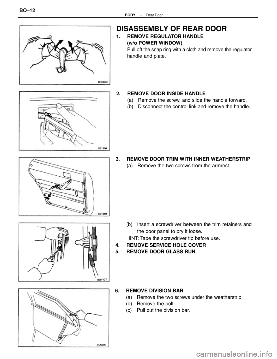
(b) Insert a screwdriver between the trim retainers and
the door panel to pry it loose.
HINT: Tape the screwdriver tip before use.
4. REMOVE SERVICE HOLE COVER
5. REMOVE DOOR GLASS RUN
DISASSEMBLY OF REAR DOOR
1. REMOVE REGULATOR HANDLE
(w/o POWER WINDOW)
Pull oft the snap ring with a cloth and remove the regulator
handle and plate.
6. REMOVE DIVISION BAR
(a) Remove the two screws under the weatherstrip.
(b) Remove the bolt.
(c) Pull out the division bar. 2. REMOVE DOOR INSIDE HANDLE
(a) Remove the screw, and slide the handle forward.
(b) Disconnect the control link and remove the handle.
3. REMOVE DOOR TRIM WITH INNER WEATHERSTRIP
(a) Remove the two screws from the armrest.
± BODYRear DoorBO±12
Page 682 of 2389
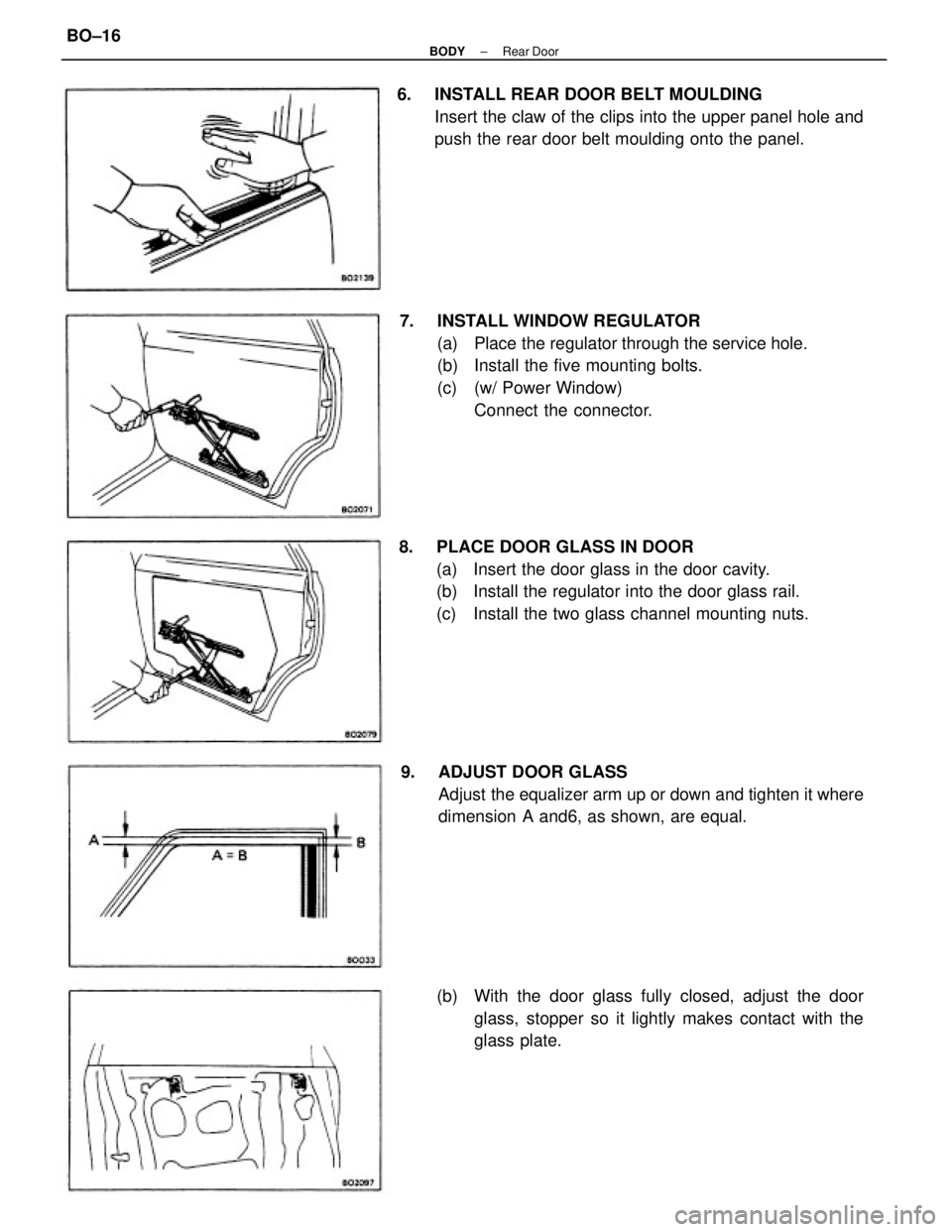
7. INSTALL WINDOW REGULATOR
(a) Place the regulator through the service hole.
(b) Install the five mounting bolts.
(c) (w/ Power Window)
Connect the connector. 6. INSTALL REAR DOOR BELT MOULDING
Insert the claw of the clips into the upper panel hole and
push the rear door belt moulding onto the panel.
8. PLACE DOOR GLASS IN DOOR
(a) Insert the door glass in the door cavity.
(b) Install the regulator into the door glass rail.
(c) Install the two glass channel mounting nuts.
9. ADJUST DOOR GLASS
Adjust the equalizer arm up or down and tighten it where
dimension A and6, as shown, are equal.
(b) With the door glass fully closed, adjust the door
glass, stopper so it lightly makes contact with the
glass plate.
± BODYRear DoorBO±16
Page 688 of 2389
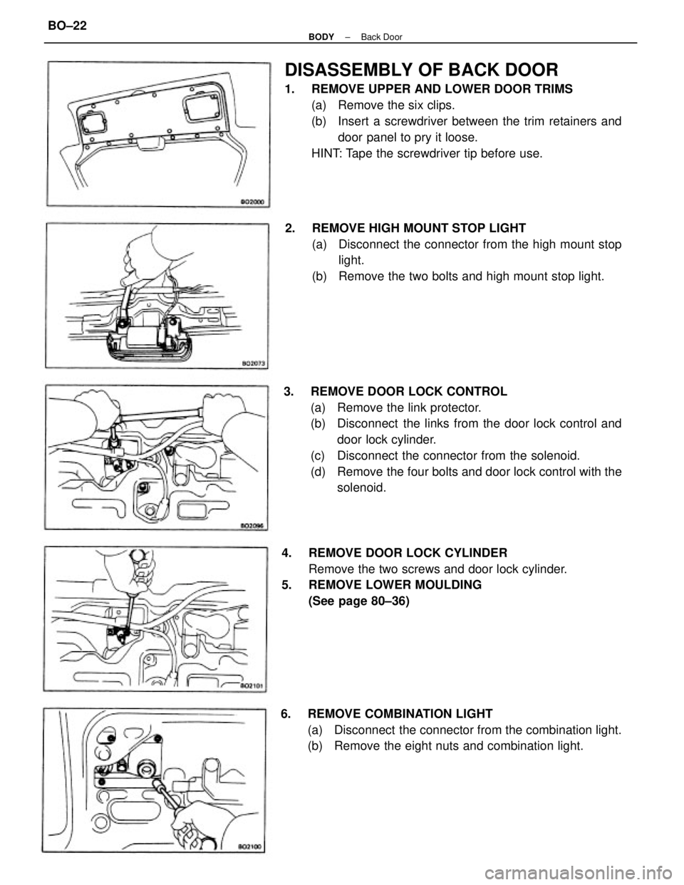
3. REMOVE DOOR LOCK CONTROL
(a) Remove the link protector.
(b) Disconnect the links from the door lock control and
door lock cylinder.
(c) Disconnect the connector from the solenoid.
(d) Remove the four bolts and door lock control with the
solenoid.
DISASSEMBLY OF BACK DOOR
1. REMOVE UPPER AND LOWER DOOR TRIMS
(a) Remove the six clips.
(b) Insert a screwdriver between the trim retainers and
door panel to pry it loose.
HINT: Tape the screwdriver tip before use.
2. REMOVE HIGH MOUNT STOP LIGHT
(a) Disconnect the connector from the high mount stop
light.
(b) Remove the two bolts and high mount stop light.
4. REMOVE DOOR LOCK CYLINDER
Remove the two screws and door lock cylinder.
5. REMOVE LOWER MOULDING
(See page 80±36)
6. REMOVE COMBINATION LIGHT
(a) Disconnect the connector from the combination light.
(b) Remove the eight nuts and combination light.
± BODYBack DoorBO±22
Page 694 of 2389
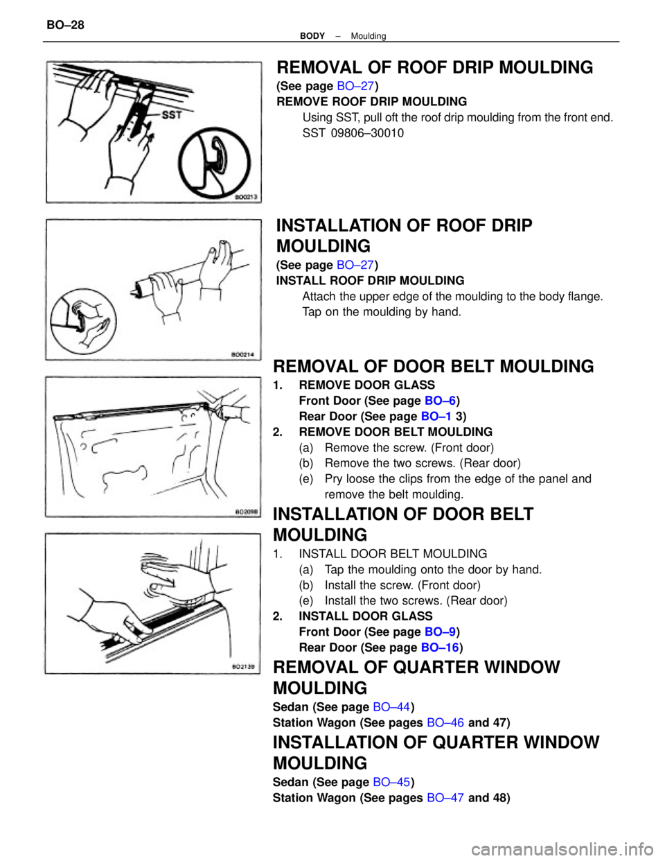
REMOVAL OF DOOR BELT MOULDING
1. REMOVE DOOR GLASS
Front Door (See page BO±6)
Rear Door (See page BO±1 3)
2. REMOVE DOOR BELT MOULDING
(a) Remove the screw. (Front door)
(b) Remove the two screws. (Rear door)
(e) Pry loose the clips from the edge of the panel and
remove the belt moulding.
INSTALLATION OF DOOR BELT
MOULDING
1. INSTALL DOOR BELT MOULDING
(a) Tap the moulding onto the door by hand.
(b) Install the screw. (Front door)
(e) Install the two screws. (Rear door)
2. INSTALL DOOR GLASS
Front Door (See page BO±9)
Rear Door (See page BO±16)
REMOVAL OF QUARTER WINDOW
MOULDING
Sedan (See page BO±44)
Station Wagon (See pages BO±46 and 47)
INSTALLATION OF QUARTER WINDOW
MOULDING
Sedan (See page BO±45)
Station Wagon (See pages BO±47 and 48)
REMOVAL OF ROOF DRIP MOULDING
(See page BO±27)
REMOVE ROOF DRIP MOULDING
Using SST, pull oft the roof drip moulding from the front end.
SST 09806±30010
INSTALLATION OF ROOF DRIP
MOULDING
(See page BO±27)
INSTALL ROOF DRIP MOULDING
Attach the upper edge of the moulding to the body flange.
Tap on the moulding by hand.
± BODYMouldingBO±28
Page 695 of 2389
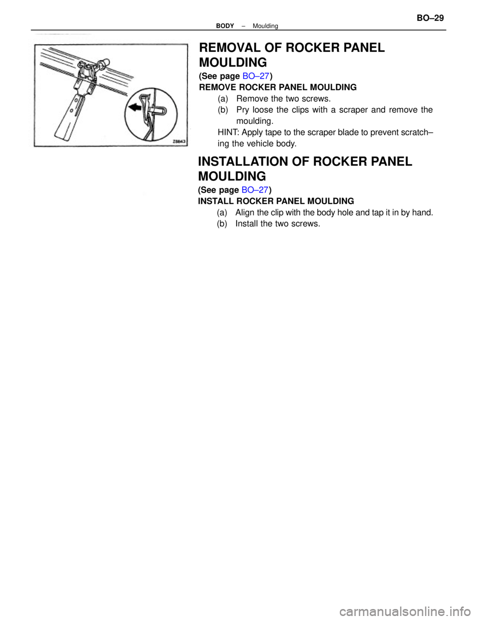
REMOVAL OF ROCKER PANEL
MOULDING
(See page BO±27)
REMOVE ROCKER PANEL MOULDING
(a) Remove the two screws.
(b) Pry loose the clips with a scraper and remove the
moulding.
HINT: Apply tape to the scraper blade to prevent scratch±
ing the vehicle body.
INSTALLATION OF ROCKER PANEL
MOULDING
(See page BO±27)
INSTALL ROCKER PANEL MOULDING
(a) Align the clip with the body hole and tap it in by hand.
(b) Install the two screws.
± BODYMouldingBO±29