TOYOTA CELICA 1987 Service Owner's Manual
Manufacturer: TOYOTA, Model Year: 1987, Model line: CELICA, Model: TOYOTA CELICA 1987Pages: 346, PDF Size: 35.13 MB
Page 21 of 346
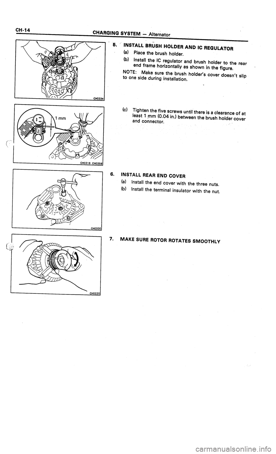
Page 22 of 346
. .
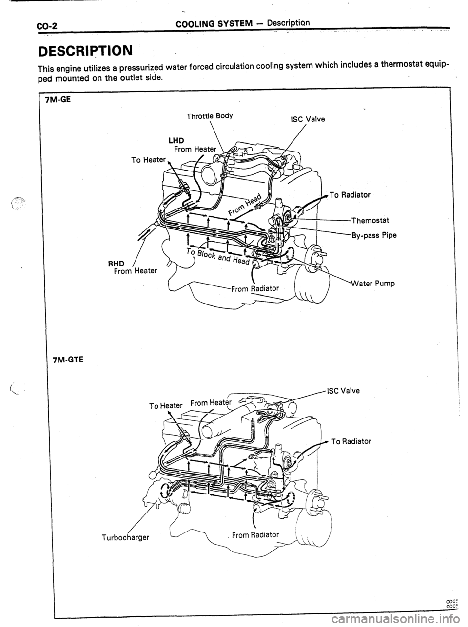
co-2 COOLING SYSTEM - Description
,- I . . .
DESCRlqTlON
This engine utilizes a pressurized water forced circulation cooling system which includes a thermostat equip-
ped mounted on the outlet side.
5 7M-GE
Throttle Body
ISC Valve
/
To Radiator
RHD
/
From Heater
rM-GTE
/
To Heater From Heat: ISC Valve
To Radiator
COGS
COOF
Page 23 of 346
. COOLING SYSTEM - Description
co;3
RESERVOIR TANK
The reservoir tank is used to catch coolant
which overflows the cooling systein as a result of
volumetric expansion when the coolant is heated.
The coolant in the reservoir tank returns to the
radiator when the coolant temperature drops, thus
keeping the radiator full at all times and avoiding
needless coolant loss. Check the reservoir tank
level to learn if the coolant needs to be rep-
lenished.
WATER PUMP
The water pump is used for forced circulation of
coolant through the cooling system. It is mounted
on the front of the cylinder block and driven by a
V-ribbed belt,
THERMOSTAT I The cooling system is composed of the water
jacket (inside the cylinder block and cylinder head),
radiator, water pump, thermostat, cooling fan,
hoses and other components.
Coolant which is heated in the water
jacket is
pumped to the radiator, through which a cooling
fan blows air to cool the coolant as it passes
through. Coolant which has been cooled is then
sent back to the engine by the water pump, where
it cools the engine.
The water jacket is a network of channels in the
shell of the cylinder block and cylinder head
through which coolant passes. It is designed to
provide adequate cooling of the cylinders are com-
bustion chambers which become the hottest dur-
ing engine operation.
F(/ “ IATOR
The radiator performs the function of cooling
the coolant which has passed through the water
jacket and become hot, and is mounted in the front
of the vehicle. The radiator consists of an upper
tank and ‘lower tank, and a core which connects
the two tanks. The upper tank contains the inlet for
coolant from the water jacket and the filter inlet. It
also has a hose attached through which excess
coolant or steam can flow. The lower tank contains
the outlet for coolant and the drain cock. The core
contains many tubes through which coolant flows
from the upper tank to the lower tank as well as
cooling fins which radiate heat away from the coo-
lant in the tubes. The air sucked through the radia-
tor by cooling fan, as well as the wind generated
by the vehicle’s travel, passes through the radia-
tor, cooling it. Models with automatic transmission
incrl*-le an automatic transmission fluid cooler built
in:.
.le lower tank of the radiator.
RADIATOR CAP
The radiator cap is a pressure type can which
seals the radiator, resulting in pressurization of the
radiator as the coolant expands. The pressuriza-
tion prevents the coolant from boiling even when
the coolant temperature exceeds 100°C. A relief
valve (pressurization valve) and a vacuum valve
(negative pressure valve) are built into the radiator
zap. The relief valve opens and lets steam escape
:hrough the overflow pipe when the pressure
3enerated inside the cooling system exceeds the
imit (coolant temperature:
110 - 1 20°C, (230
- 248”F), pressure; 0.3 - 1 .O kg/cmz, (4.3 - 14.2
)si, 29.4 - 98.1 kPa). The vacuum valve opens to
3ljeviate the vacuum which develops in the coolant
system after the engine is stopped and the coolant
emperature drops. The valve’s opening allows the
)ressure in the cooling system to return to the
Qclant in the reservoir tank. The thermostat has a wax type and is mounted
in the. water outlet housing. The thermostat
includes a type of automatic valve operated by
fluctuations in the coolant temperature. This valve
closes when the coolant temperature drops, pre-
venting the circulation of coolant through the
engine and thus permitting the engine to warm up
rapidly. The valve opens when the coolant tem-
perature has risen, allowing the circulation of coo-
lant. Wax inside the thermostat expands when
heated and contracts when cooled. Heating the
wax thus generates pressure which overpowers
the force of the spring which keeps the valve
closed, thus opening the valve. When the wax
cools, its contraction causes the force of the
spring to take effect once more, closing the valve.
The thermostat in this engine operates at a tem-
perature of 88”C(19O”F).
I
I
Page 24 of 346
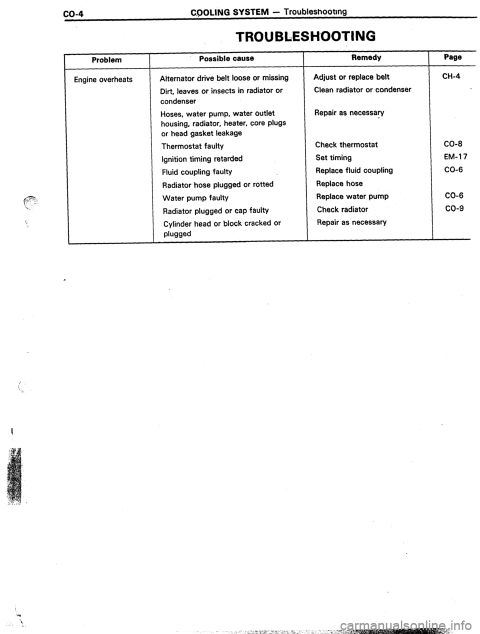
co-4 CQOLING SYSTEM - Troubleshootmg
TROUBLESHOOTING
, Problem
Engine overheats Possible cause
Alternator drive belt loose or missing
Dirt, leaves or insects in radiator or
condenser
Hoses, water pump, water outlet
housing, radiator, heater, core plugs
or head gasket leakage
Thermostat faulty
Ignition timing
retarded
Fluid coupling faulty
Radiator hose plugged or rotted
Water pump faulty
Radiator plugged or cap faulty
Cylinder head or block cracked or
phwd Remedy
Adjust or replace belt
Clean radiator or condenser
Repair as necessary
Check thermostat
Set timing
Replace fluid coupling
Replace hose
Replace water pump
Check radiator
Repair as necessary Page
CH-4
CO-8
EM-l 7
CO-6
CO-6
co-9
Page 25 of 346
COOLING SYSTEM i Check and Replacement of Engine Coolant
co-5
._
CHECK AND REPLACEMENT OF
ENGINE COOLANT
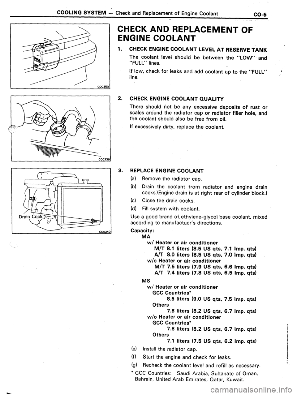
1. CHECK ENGINE COOLANT LEVEL AT RESERVE TANK
The coolant level should be between the “LOW” and
“FULL” lines.
If low, check for leaks and add coolant up to the “FULL”
line. .,>‘
2. CHECK ENGINE COOLANT QUALITY
There should not be any excessive deposits of rust or
scales around the radiator cap or radiator filler hole, and
the coolant should also be free from oil.
lf excessively dirty, replace the coolant.
3. REPLACE ENGINE COOLANT
(a) Remove the radiator cap.
(b) Drain the coolant from radiator and engine drain
cocks.(Engine drain is at right rear of cylinder block.)
(cl Close the drain cocks.
(d) Fill system with coolant.
Use a good brand of. ethylene-glycol base coolant, mixed
according to manufactuer’s directions.
Capacity:
MA
w/ Heater or air conditioner
M/T 8.1 liters (8.5 US qts. 7.1 Imp. qts)
A/T 8.0 liters (8.5 US qts, 7.0 Imp. qts)
w/o Heater or air conditioner
M/T 7.5 liters (7.9 US qts, 6.6
Imp. qts)
A/T 7.4 liters (7.8 US qts, 6.5 Imp. qts)
MS
w/ Heater or air conditioner
GCC Countries*
8.5 liters (9.0 US qts, 7.5 Imp. qts)
Others
7.8 liters (8.2 US qts, 6.7 Imp. qts)
w/o Heater or air conditioner
GCC Countries*
7.8 liters (8.2 US qts, 6.7 Imp. qts)
Others
7.1 liters (7.5 US qts, 6.2 Imp. qts)
(e) Install the radiator cap.
(f) Start the engine and check for leaks.
(g) Recheck the coolant level and refill as necessary.
l GCC Countries: Saudi Arabia, Sultanate of Oman,
Bahrain, United Arab Emirates, Qatar, Kuwait.
Page 26 of 346
CO-6
C6OLlNG SYSTEM - Water Puma
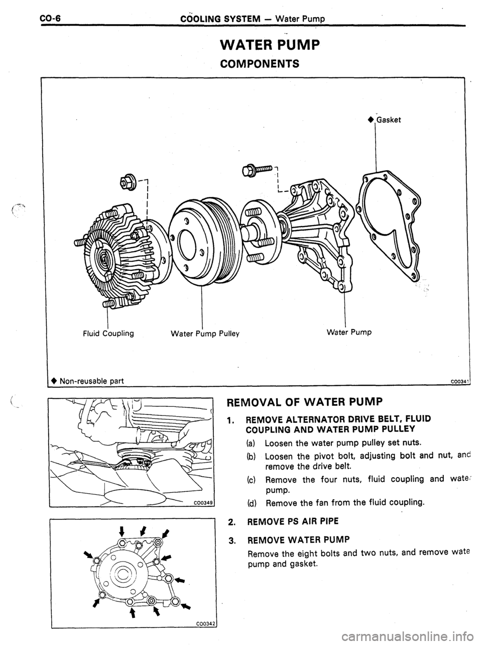
WATER ilJMP
COMPONENTS
Fluid Ckqling Water P;lmp Pulley Water Pump
+ Non-reusable part COOL3
c REMOVAL OF WATER PUMP ._
1. REMOVE ALTERNATOR DRIVE BELT, FLUID
COUPLING AND WATER PUMP PULLEY
(a) Loosen the water pump pulley set nuts.
(b) Loosen the pivot bolt, adjusting bolt and nut, and
remove the drive belt.
(c) Remove the four nuts, fluid coupling and wate,
w-w.
(d) Remove the fan from the fluid coupling.
2. REMOVE PS AIR PIPE
3. REMOVE WATER PUMP
Remove the eight bolts and two nuts, and remove wate
pump and gasket.
Page 27 of 346
1.
2.
3.
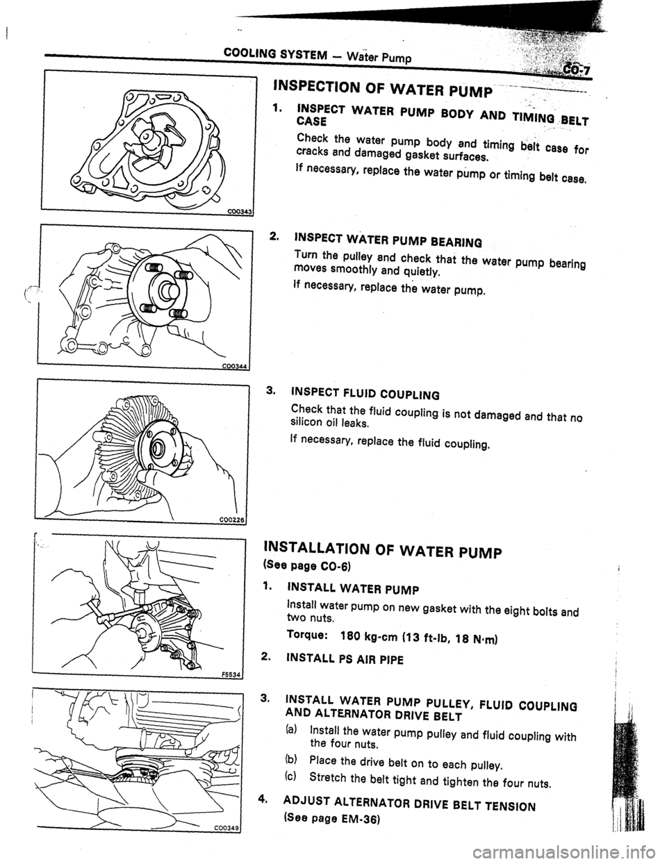
.._ INSPECT WATER PUMP BODY AND TIMI+BELT
CASE ” ._
Check the water pump body and timing b&i case for
cracks and damaged gasket surfaces.
If necessary, replace the water pump or timing belt case,
INSPECT WATER PUMP BEARINQ
Turn the pulley and check that the water pump bearing
moves smoothly and quietly.
lf necessary, replace the water pump,
INSPECT FLUID COUPLING
Check that the fluid coupling is not damaged and that no
silicon oil leaks.
If necessary, replace the fluid coupling.
INSTALLATION OF WATER PUMP
(See page CO-6)
1. INSTALL WATER PUMP
install water pump on new gasket with the eight bolts and
two nuts.
Torque:
160 kg-cm (13 ft-lb, 18 N*mI
2. INSTALL PS AIR PIPE
3. INSTALL WATER PUMP PULLEY, FLUID COUPLING
AND ALTERNATOR DRIVE BELT
(al Install the water pump pulley and fluid coupling with
the four nuts.
(b)
(c) Place the drive belt on to each pulley.
Stretch the belt tight and tighten the four nuts.
4. ADJUST ALTERNATOR DRIVE BELT TENSION
(See page EM-361
Page 28 of 346
CO-8 -. COOLING SYSTEM L Thermostat
._
Valve Lift
i
t-
THERMOSTAT
REMOVAL OF THERMOSTAT
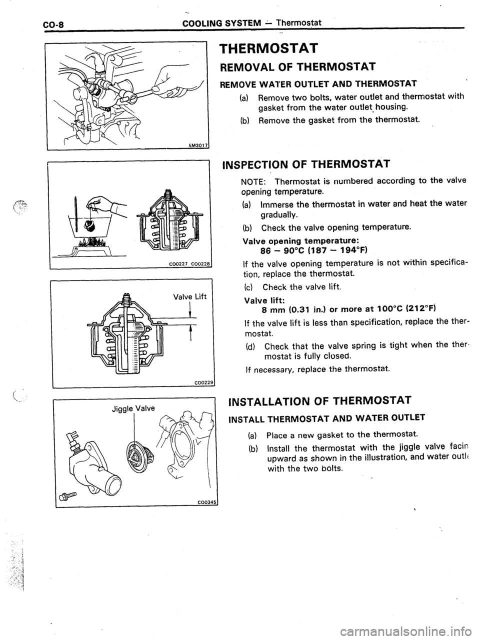
REMOVE WATER OUTLET AND THERMOSTAT
(a) Remove two bolts, water outlet and thermostat with
gasket from the water outlet, housing.
(b) Remove the gasket from the thermostat.
INSPECTION OF THERMOSTAT
NOTE: Thermostat is numbered according to the valve
opening temperature.
(a)
Immerse the thermostat in water and heat the water
gradually.
(b)
Check the valve opening temperature.
Valve opening temperature:
86 - 90°C (187
- 194°F)
If the valve opening temperature is not within specifica-
tion, replace the thermostat.
(c) Check the vatve lift.
Valve lift:
8 mm (0.31 in.) or more at
100°C (212°F)
If the valve lift is less than specification, replace the ther-
mostat.
(d) Check that the valve spring is tight when the ther-
mostat is fully closed.
If necessary, replace the thermostat.
INSTALLATION OF THERMOSTAT
INSTALL THERMOSTAT AND WATER OUTLET
(a) Place a new gasket to the thermostat.
(b) Install the thermostat with the jiggle valve facin
upward as shown in the illustration, and water outlc
with the two bolts.
,
Page 29 of 346
COOLING SYSTEM - Radiator
-,... ~‘e:,.,,’ _,
CLEANING OF RADIATOR _ ---w..w- -...,.
Using water or steam cleaner, remove mud and dirt from
the radiator core.
CAUTION: If using’ high-pressure, type cleaner, be
careful not to deform the fins of the radiator core. Keep
a distance of more than 40 - 50 cm (15.75 - 19.69 in.)
between the radiator core and cleaner nozzle when
the cleaner nozzle pressure is 30 - 35 kg/cm2 (427 -
1
498 psi, 2,942 - 3,432 kPa1.
I lNSPECTlON.OF RADIATOR
t 1. CHECK RADIATOR CAP
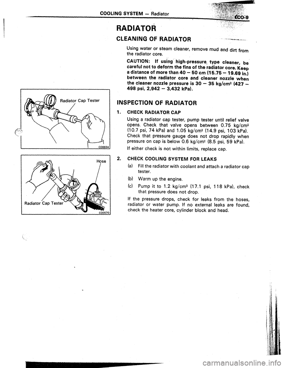
Using a radiator cap tester, pump tester until relief valve
opens. Check that valve opens between 0.75 kg/cm2
(10.7 psi, 74 kPa) and 1.05 kg/cm2 (14.9 psi, 103 kPa).
Check that pressure gauge does not drop rapidly when
pressure on cap is below 0.6 kg/cm2 (8.5 psi, 59 kPa).
!J If either check is not within limits, replace cap.
1 2. CHECK COOLING SYSTEM FOR LEAKS
(a) Fill the radiator with coolant and attach a radiator cap
tester.
(b) Warm up the engine.
(c) Pump it to 1.2 kg/cm2 117.1 psi, 118 kPa), check
that pressure does not drop.
If the pressure drops, check for leaks from the hoses,
radiator or water pump. If no external
leaks are found,
check the heater core, cylinder block
and head.
Page 30 of 346
CO-IO
-.
COOLING SYSTEM - Radiatpr
. .
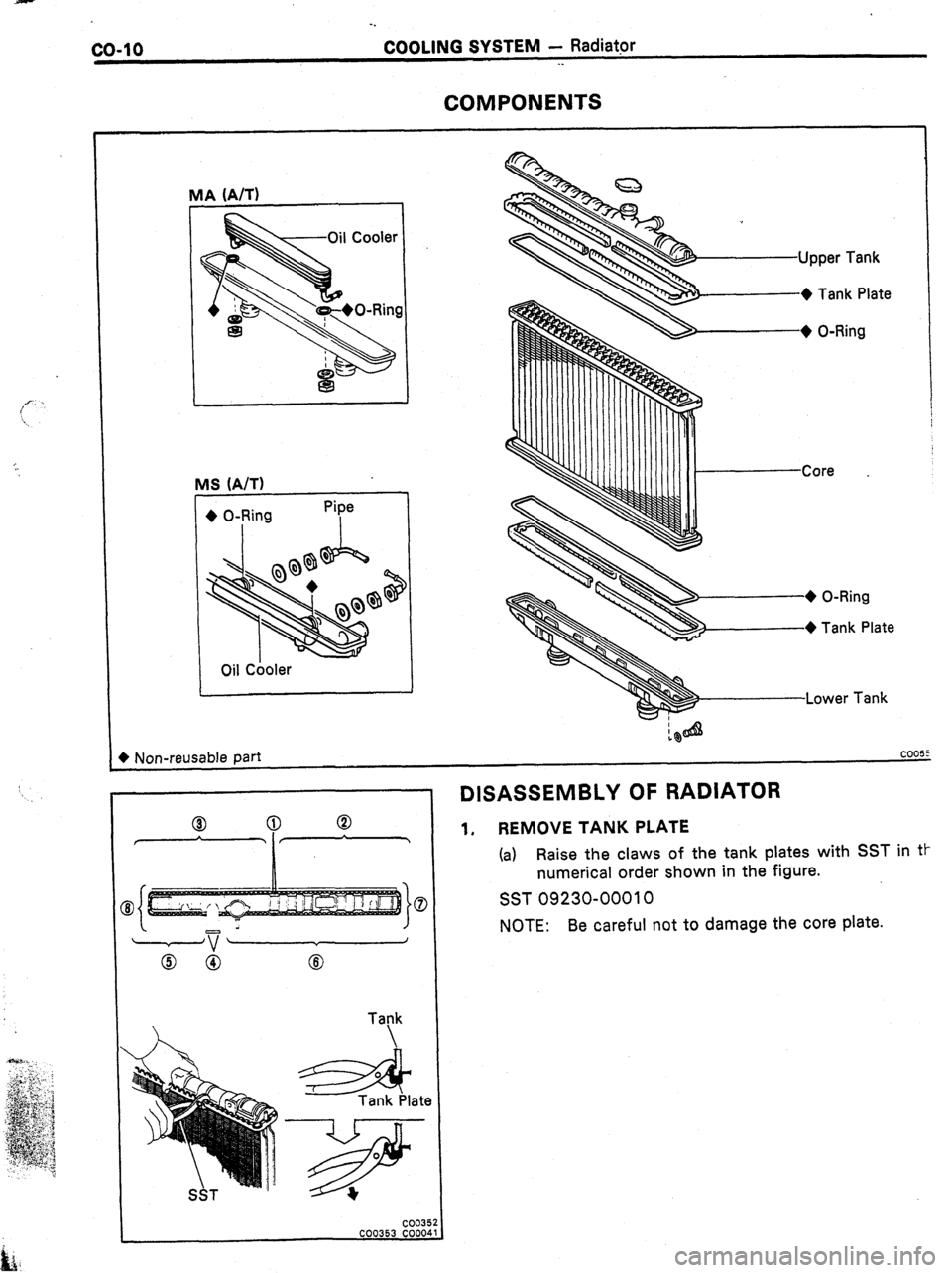
COMPONENTS
IA (A/T)
MS (A/T)
+ O-Ring
I
Oil Cooler Pipe
I
1
Upper Tank
-+ Tank Plate
,+ 0-Rina
I I I I
I I I I I I I I I I I ICore
Lower
Tank
+ Non-reusable part
coo55
SST - I
DISASSEMBLY OF RADIATOR
1. REMOVE TANK PLATE
(a)
Raise the claws of the tank plates with SST in tt-
numerical order shown in the figure.
SST 09230-00010
NOTE:
Be careful not to damage the core plate.