ESP TOYOTA COROLLA HATCHBACK 2022 Owners Manual (in English)
[x] Cancel search | Manufacturer: TOYOTA, Model Year: 2022, Model line: COROLLA HATCHBACK, Model: TOYOTA COROLLA HATCHBACK 2022Pages: 758, PDF Size: 155.26 MB
Page 9 of 758
7
RF-transmitters, is available on
request at any authorized Toyota
retailer or Toyota authorized
repairer, or any reliable repairer.
The vehicle is equipped with
sophisticated comp uters that will
record certain data, such as:
• Engine speed/Electric motor
speed (traction motor speed)
• Accelerator status
• Brake status
• Vehicle speed
• Operation status of the driving
assist systems
• Images from the cameras
Your vehicle is equipped with cameras.
Contact any authorized Toyota retailer
or Toyota authorized repairer, or any
reliable repairer for the location of
recording cameras.
The recorded data varies according
to the vehicle grade level, options
and destinations with which it is
equipped.
These computers do not record
conversations or sounds, and only
record images outside of the vehi-
cle in certain situations.
Data usage
Toyota may use the data recorded in
this computer to diagnose malfunc-
tions, conduct research and develop-
ment, and improve quality.
Toyota will not disclose the recorded
data to a third party except:
• With the consent of the vehicle owner
or with the consent of the lessee if
the vehicle is leased
• In response to an official request by
the police, a court of law or a govern-
ment agency
• For use by Toyota in a lawsuit
• For research purposes where the
data is not tied to a specific vehicle or
vehicle owner
Recorded image information can
be erased by any authorized
Toyota retailer or Toyota author-
ized repairer, or any reliable
repairer.
The image recording function can be
disabled. However, if the function is dis-
abled, data from when the system oper-
ates will not be available.
The SRS airbag and seat belt
pretensioner devices in your Toyota
contain explosive c hemicals. If the
vehicle is scrapped with the airbags
and seat belt pretensioners left as
they are, this may cause an acci-
dent such as fire. Be sure to have
the systems of the SRS airbag and
seat belt pretensioner removed and
disposed of by a qualified service
shop or by any authorized Toyota
retailer or Toyota authorized
repairer, or any reliable repairer
before you scrap your vehicle.
Vehicle data recording
Scrapping of your Toyota
Page 32 of 758
301-1. For safe use
1-1.For safe use
Use only floor mats designed spe-
cifically for vehicles of the same
model and model year as your vehi-
cle. Fix them securely in place onto
the carpet.
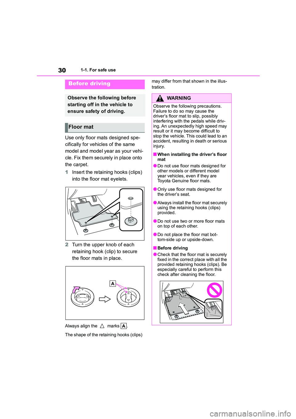
1 Insert the retaining hooks (clips)
into the floor mat eyelets.
2 Turn the upper knob of each
retaining hook (clip) to secure
the floor mats in place.
Always align the marks .
The shape of the retaining hooks (clips)
may differ from that shown in the illus-
tration.Before driving
Observe the following before
starting off in the vehicle to
ensure safety of driving.
Floor mat
WA R N I N G
Observe the following precautions.
Failure to do so may cause the driver’s floor mat to slip, possibly
interfering with the pedals while driv-
ing. An unexpectedly high speed may result or it may become difficult to
stop the vehicle. This could lead to an
accident, resulting in death or serious
injury.
■When installing the driver’s floor
mat
●Do not use floor mats designed for
other models or different model
year vehicles, even if they are Toyota Genuine floor mats.
●Only use floor mats designed for the driver’s seat.
●Always install the floor mat securely using the retaining hooks (clips)
provided.
●Do not use two or more floor mats
on top of each other.
●Do not place the floor mat bot-
tom-side up or upside-down.
■Before driving
●Check that the floor mat is securely
fixed in the correct place with all the provided retaining hooks (clips). Be
especially careful to perform this
check after cleaning the floor.
Page 41 of 758
39
1
1-1. For safe use
For safety and security
may be sustained from SRS airbags,
due to the extremely high speed deployment (inflation) by hot gases.
●A loud noise and white powder will be emitted.
●Parts of the airbag module (steering wheel hub, airbag cover and inflator)
as well as the front seats, parts of the
front and rear pillars, and roof side rails, may be hot for several minutes.
The airbag itself may also be hot.
●The windshield may crack.
●The brakes and stop lights will be con- trolled automatically. ( P.357)
●The interior lights will turn on automat- ically. ( P.437)
●The emergency flashers will turned on automatically. ( P.502)
●Fuel supply to the engine will be stopped. ( P.510)
●Vehicles with eCall: If any of the fol-
lowing situations occur, the system is
designed to send an emergency call*
to the eCall control center, notifying
them of the vehicle’s location (without needing to push the “SOS” button)
and an agent will attempt to speak
with the occupants to ascertain the level of emergency and assistance
required. If the occupants are unable
to communicate, the agent automati- cally treats the call as an emergency
and helps to dispatch the necessary
emergency services. ( P. 6 9 ) • An SRS airbag is deployed.
• A seat belt pretensioner is activated.
• The vehicle is involved in a severe rear-end collision.*: In some cases, the call cannot be
made. ( P. 7 0 )
■SRS airbag deployment conditions (SRS front airbags)
●The SRS front airbags will deploy in the event of an impact that exceeds
the set threshold le vel (the level of
force corresponding to an approxi- mately 20 - 30 km/h [12 - 18 mph]
frontal collision with a fixed wall that
does not move or deform).
However, this threshold velocity will be
considerably higher in the following situ-
ations: • If the vehicle strikes an object, such
as a parked vehicle or sign pole,
which can move or deform on impact • If the vehicle is involved in an
underride collision, such as a collision
in which the front of the vehicle “underrides”, or goes under, the bed
of a truck
■SRS airbag deployment conditions
(SRS side and curtain shield airbags)
●The SRS side and curtain shield airbags will deploy in the event of an
impact that exceeds the set threshold
level (the level of force corresponding to the impact force produced by an
approximately 1500 kg [3300 lb.] vehi-
cle colliding with the vehicle cabin from a direction perpendicular to the
vehicle orientation at an approximate
speed of 20 - 30 km/h [12 - 18 mph]).
●Both SRS curtain shield airbags may
deploy in the event of a severe side collision.
●Both SRS curtain shield airbags may also deploy in the event of a severe
frontal collision.
■Conditions under which the SRS
airbags may deploy (inflate), other than a collision
The SRS front airbags and SRS side
and curtain shield airbags may also deploy if a serious impact occurs to the
underside of your vehicle. Some exam-
ples are shown in the illustration.
●Hitting a curb, edge of pavement or
hard surface
●Falling into or jumping over a deep
hole
●Landing hard or falling
Page 44 of 758
421-1. For safe use
WA R N I N G
●The SRS driver airbag deploys with
considerable force, and can cause
death or serious injury especially if the driver is very close to the
airbag.
Since the risk zone for the driver’s airbag is the first 50 - 75 mm (2 - 3 in.)
of inflation, placing yourself 250 mm
(10 in.) from your driver airbag pro-
vides you with a clear margin of safety. This distance is measured
from the center of the steering wheel
to your breastbone. If you sit less than 250 mm (10 in.) away now, you can
change your driving position in sev-
eral ways:
• Move your seat to the rear as far as
you can while still reaching the ped-
als comfortably.
• Slightly recline the back of the seat.
Although vehicle designs vary, many drivers can achieve the 250
mm (10 in.) distance, even with the
driver seat all the way forward, sim- ply by reclining the back of the seat
somewhat. If reclining the back of
your seat makes it hard to see the road, raise yourself by using a firm,
non-slippery cushion, or raise the
seat if your vehicle has that feature.
• If your steering wheel is adjustable,
tilt it downward. This points the airbag toward your chest instead of
your head and neck.
The seat should be adjusted as rec-
ommended above, while still main-
taining control of the foot pedals, steering wheel, and your view of the
instrument panel controls.
●The SRS front passenger airbag also deploys with considerable
force, and can cause death or seri-
ous injury especially if the front pas- senger is very close to the airbag.
The front passenger seat should be
as far from the airbag as possible with the seatback adjusted, so the
front passenger sits upright.
●Improperly seated and/or restrained
infants and children can be killed or
seriously injured by a deploying airbag. An infant or child who is too
small to use a seat belt should be
properly secured using a child restraint system. Toyota strongly
recommends that all infants and
children be placed in the rear seats of the vehicle and properly
restrained. The rear seats are safer
for infants and children than the front passenger seat. (P. 4 8 )
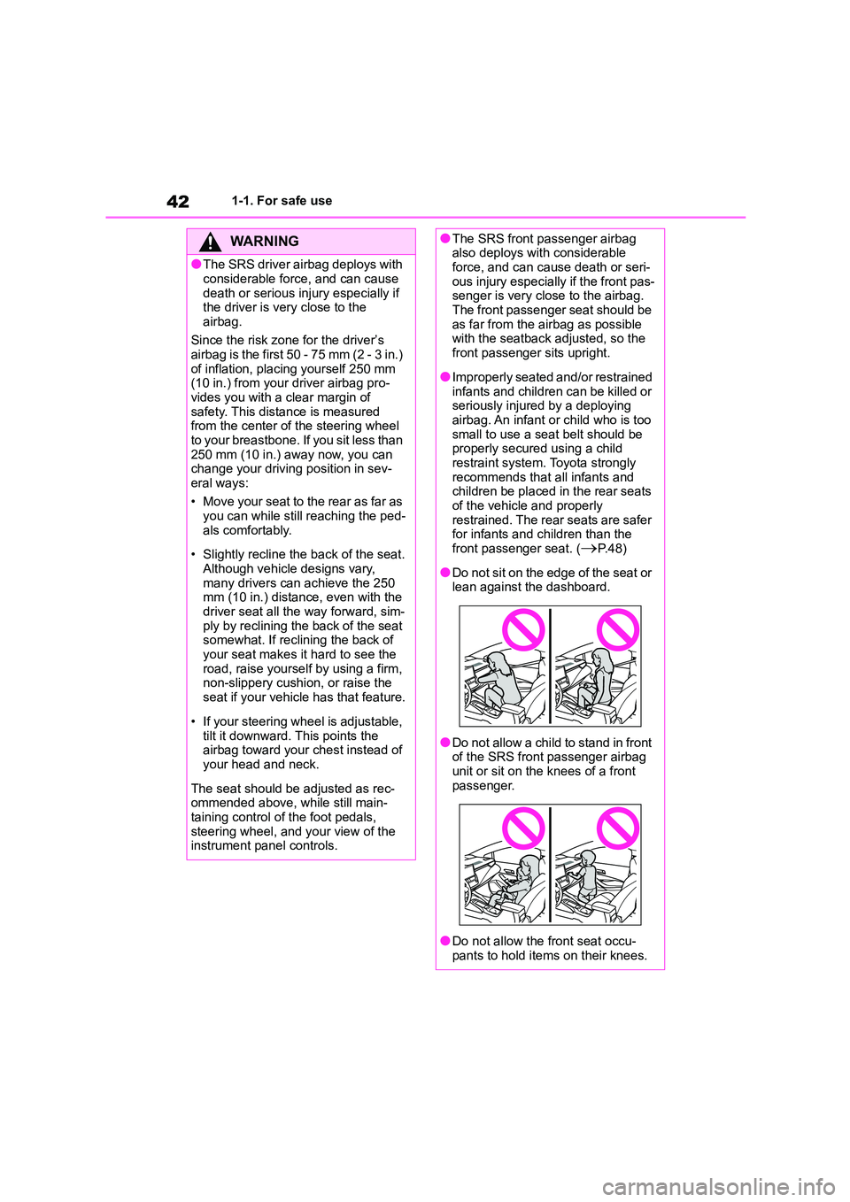
●Do not sit on the edge of the seat or lean against the dashboard.
●Do not allow a child to stand in front of the SRS front passenger airbag
unit or sit on the knees of a front
passenger.
●Do not allow the front seat occu-
pants to hold items on their knees.
Page 76 of 758
741-3. Emergency assistance
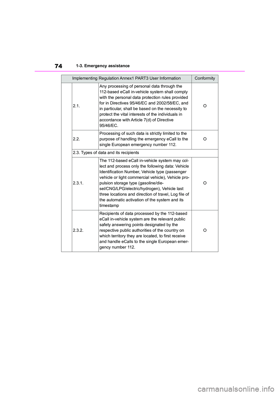
2.1.
Any processing of personal data through the
112-based eCall in-vehicle system shall comply
with the personal data protection rules provided
for in Directives 95/46/EC and 2002/58/EC, and
in particular, shall be based on the necessity to
protect the vital interests of the individuals in
accordance with Article 7(d) of Directive
95/46/EC.
O
2.2.
Processing of such data is strictly limited to the
purpose of handling the emergency eCall to the
single European emergency number 112.
O
2.3. Types of data and its recipients
2.3.1.
The 112-based eCall in-v ehicle system may col-
lect and process only the following data: Vehicle
Identification Number, Vehicle type (passenger
vehicle or light commercia l vehicle), Vehicle pro-
pulsion storage type (gasoline/die-
sel/CNG/LPG/electric/hydr ogen), Vehicle last
three locations and direction of travel, Log file of
the automatic activation of the system and its
timestamp
O
2.3.2.
Recipients of data processed by the 112-based
eCall in-vehicle system are the relevant public
safety answering points designated by the
respective public authorities of the country on
which territory they are located, to first receive
and handle eCalls to the single European emer-
gency number 112.
O
Implementing Regulation Annex1 PART3 User InformationConformity
Page 78 of 758
761-3. Emergency assistance
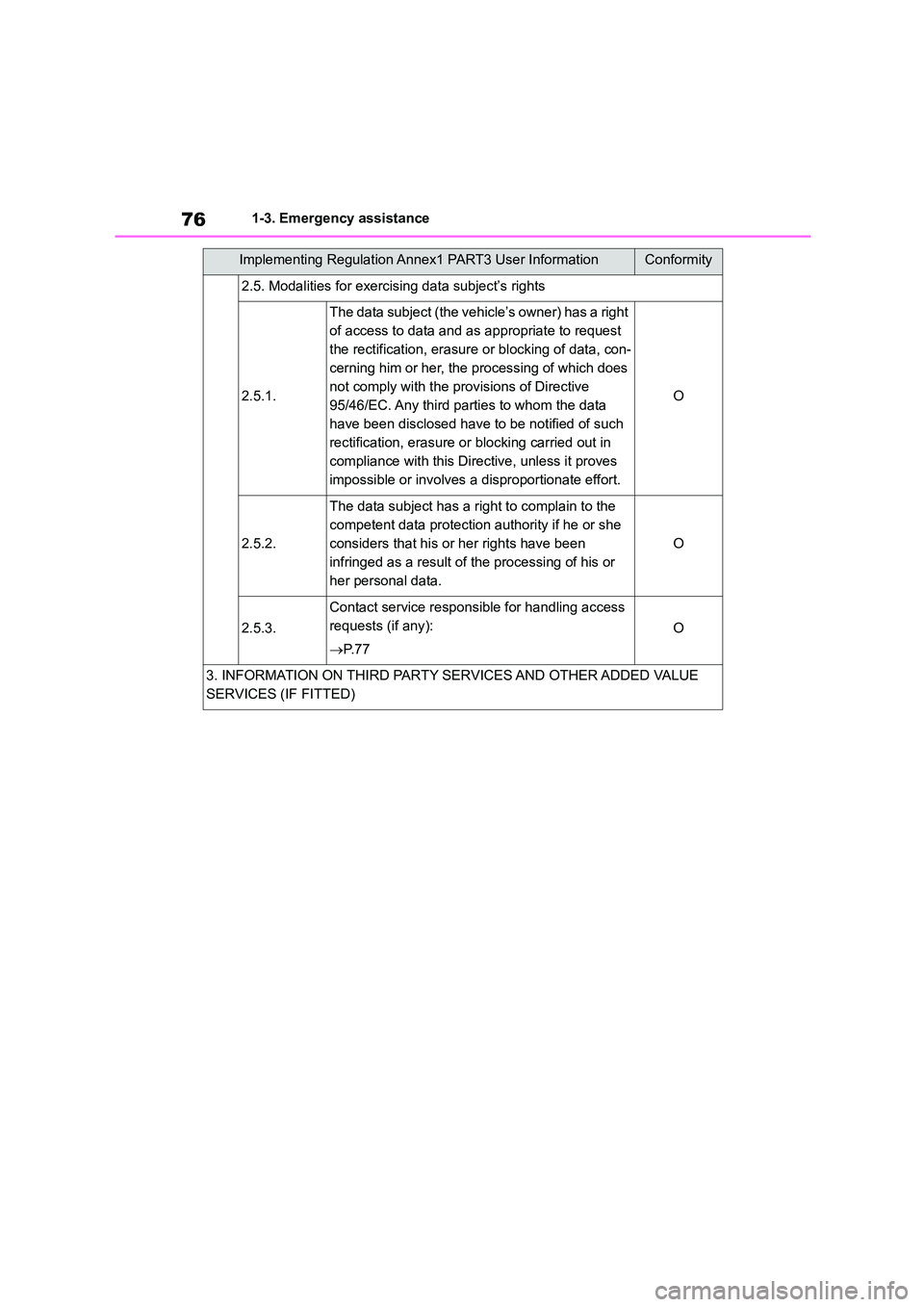
2.5. Modalities for exercising data subject’s rights
2.5.1.
The data subject (the vehicle’s owner) has a right
of access to data and as appropriate to request
the rectification, erasure or blocking of data, con-
cerning him or her, the processing of which does
not comply with the provisions of Directive
95/46/EC. Any third parties to whom the data
have been disclosed have to be notified of such
rectification, erasure or blocking carried out in
compliance with this Directive, unless it proves
impossible or involves a disproportionate effort.
O
2.5.2.
The data subject has a right to complain to the
competent data protection authority if he or she
considers that his or her rights have been
infringed as a result of the processing of his or
her personal data.
O
2.5.3.
Contact service responsible for handling access
requests (if any):
P. 7 7
O
3. INFORMATION ON THIRD PARTY SERVICES AND OTHER ADDED VALUE
SERVICES (IF FITTED)
Implementing Regulation Annex1 PART3 User InformationConformity
Page 79 of 758
77
1
1-3. Emergency assistance
For safety and security
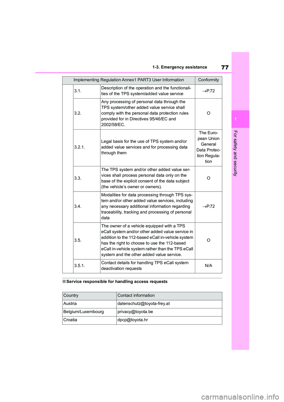
■Service responsible for handling access requests
3.1.Description of the operation and the functionali-
ties of the TPS system/added value service P. 7 2
3.2.
Any processing of personal data through the
TPS system/other added value service shall
comply with the personal data protection rules
provided for in Directives 95/46/EC and
2002/58/EC.
O
3.2.1.
Legal basis for the use of TPS system and/or
added value services and for processing data
through them
The Euro-
pean Union
General
Data Protec-
tion Regula-
tion
3.3.
The TPS system and/or other added value ser-
vices shall process personal data only on the
base of the explicit consent of the data subject
(the vehicle’s owner or owners).
O
3.4.
Modalities for data processing through TPS sys-
tem and/or other added value services, including
any necessary additional information regarding
traceability, tracking and processing of personal
data
P. 7 2
3.5.
The owner of a vehicle equipped with a TPS
eCall system and/or other added value service in
addition to the 112-based eCall in-vehicle system
has the right to choose to use the 112-based
eCall in-vehicle system rather than the TPS eCall
system and the other added value service.
O
3.5.1.Contact details for han dling TPS eCall system
deactivation requestsN/A
CountryContact information
[email protected]
Belgium/[email protected]
[email protected]
Implementing Regulation Annex1 PART3 User InformationConformity
Page 92 of 758
902-1. Instrument cluster
■Outside temperature display
●In the following situations, the correct
outside temperature may not be dis- played, or the display may take longer
than normal to change:
• When stopped, or driving at low speeds (less than 25 km/h [16 mph])
• When the outside temperature has
changed suddenly (at the entrance/exit of a garage, tunnel, etc.)
●When “--” or “E” is displayed, the sys-tem may be malfunctioning. Take your
vehicle to any authorized Toyota
retailer or Toyota authorized repairer, or any reliable repairer.
■Liquid crystal display
P.100
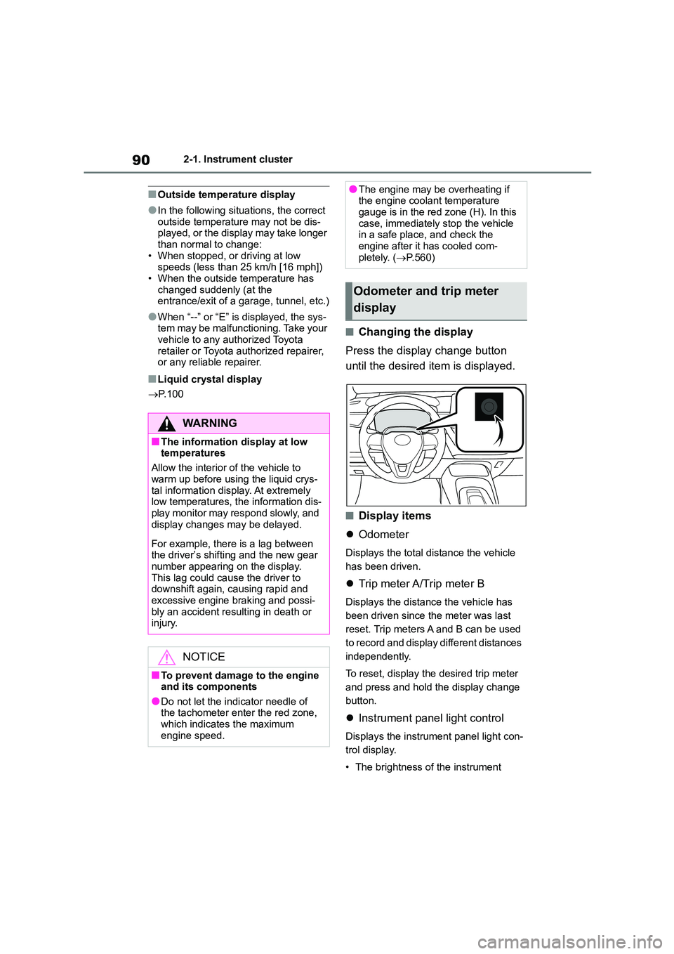
■Changing the display
Press the display change button
until the desired item is displayed.
■Display items
Odometer
Displays the total distance the vehicle
has been driven.
Trip meter A/Trip meter B
Displays the distance the vehicle has
been driven since the meter was last
reset. Trip meters A and B can be used
to record and display different distances
independently.
To reset, display the desired trip meter
and press and hold the display change
button.
Instrument panel light control
Displays the instrument panel light con-
trol display.
• The brightness of the instrument
WA R N I N G
■The information display at low
temperatures
Allow the interior of the vehicle to
warm up before using the liquid crys-
tal information display. At extremely low temperatures, the information dis-
play monitor may respond slowly, and
display changes may be delayed.
For example, there is a lag between
the driver’s shifting and the new gear number appearing on the display.
This lag could cause the driver to
downshift again, causing rapid and excessive engine braking and possi-
bly an accident resulting in death or
injury.
NOTICE
■To prevent damage to the engine
and its components
●Do not let the indicator needle of the tachometer enter the red zone,
which indicates the maximum
engine speed.
●The engine may be overheating if the engine coolant temperature
gauge is in the red zone (H). In this
case, immediately stop the vehicle in a safe place, and check the
engine after it has cooled com-
pletely. ( P.560)
Odometer and trip meter
display
Page 98 of 758
962-1. Instrument cluster
entrance/exit of a garage, tunnel, etc.)
●When “--” or “E” is displayed, the sys-
tem may be malfunctioning. Take your
vehicle to any authorized Toyota retailer or Toyota authorized repairer,
or any reliable repairer.
■Liquid crystal display
P.100
■Customization
The gauges and meters can be custom-
ized in of the multi-information dis-
play. ( P.104)
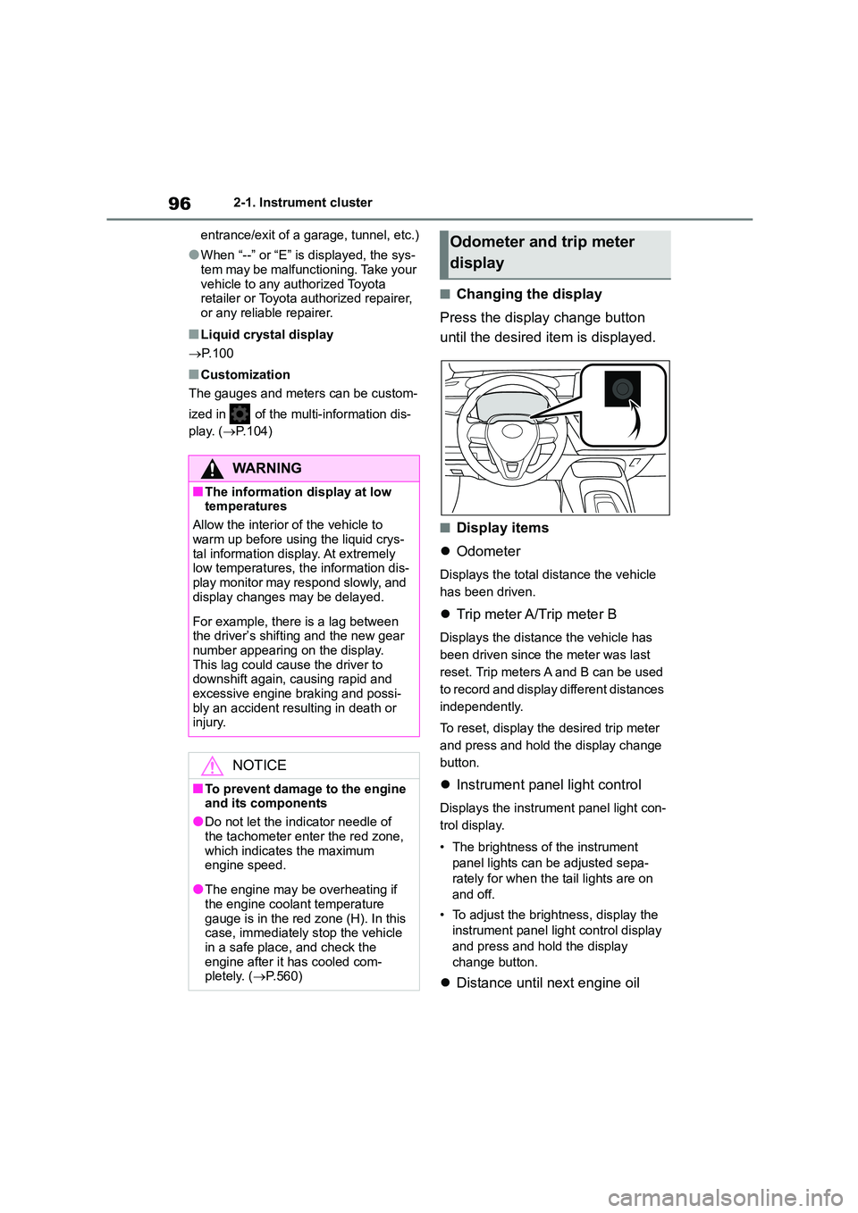
■Changing the display
Press the display change button
until the desired item is displayed.
■Display items
Odometer
Displays the total distance the vehicle
has been driven.
Trip meter A/Trip meter B
Displays the distance the vehicle has
been driven since the meter was last
reset. Trip meters A and B can be used
to record and display different distances
independently.
To reset, display the desired trip meter
and press and hold the display change
button.
Instrument panel light control
Displays the instrument panel light con-
trol display.
• The brightness of the instrument
panel lights can be adjusted sepa-
rately for when the tail lights are on
and off.
• To adjust the brightness, display the
instrument panel light control display
and press and hold the display
change button.
Distance until next engine oil
WA R N I N G
■The information display at low temperatures
Allow the interior of the vehicle to
warm up before using the liquid crys- tal information display. At extremely
low temperatures, the information dis-
play monitor may respond slowly, and display changes may be delayed.
For example, there is a lag between the driver’s shifting and the new gear
number appearing on the display.
This lag could cause the driver to downshift again, causing rapid and
excessive engine braking and possi-
bly an accident resulting in death or injury.
NOTICE
■To prevent damage to the engine
and its components
●Do not let the indicator needle of
the tachometer enter the red zone,
which indicates the maximum engine speed.
●The engine may be overheating if the engine coolant temperature
gauge is in the red zone (H). In this
case, immediately stop the vehicle in a safe place, and check the
engine after it has cooled com-
pletely. ( P.560)
Odometer and trip meter
display
Page 108 of 758
1062-1. Instrument cluster
*: If equipped
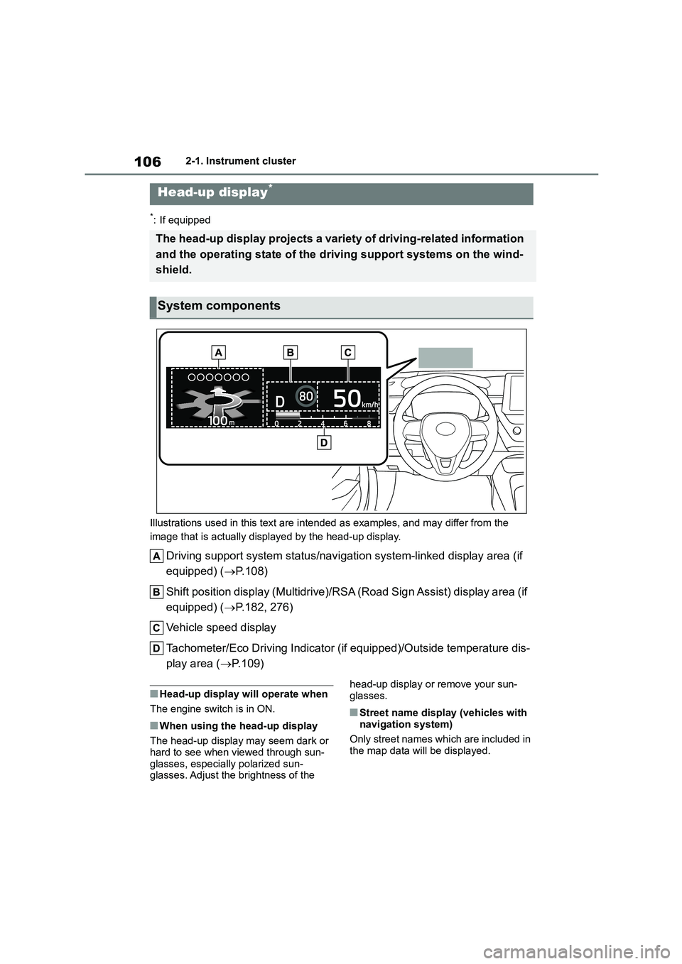
Illustrations used in this text are intended as examples, and may differ from the
image that is actually displayed by the head-up display.
Driving support system status/navigation system-linked display area (if
equipped) ( P.108)
Shift position display (Multidrive)/RSA (Road Sign Assist) display area (if
equipped) ( P.182, 276)
Vehicle speed display
Tachometer/Eco Driving Indicator (i f equipped)/Outside temperature dis-
play area ( P.109)
■Head-up display will operate when
The engine switch is in ON.
■When using the head-up display
The head-up display may seem dark or
hard to see when viewed through sun-
glasses, especially polarized sun- glasses. Adjust the brightness of the
head-up display or remove your sun-
glasses.
■Street name display (vehicles with
navigation system)
Only street names which are included in
the map data will be displayed.
Head-up display*
The head-up display projects a variety of driving-related information
and the operating state of the driving support systems on the wind-
shield.
System components