display TOYOTA COROLLA HATCHBACK 2023 Owners Manual
[x] Cancel search | Manufacturer: TOYOTA, Model Year: 2023, Model line: COROLLA HATCHBACK, Model: TOYOTA COROLLA HATCHBACK 2023Pages: 436, PDF Size: 8.72 MB
Page 1 of 436
COROLLA H/B_U
1
2
3
4
5
6
7
8
9
9
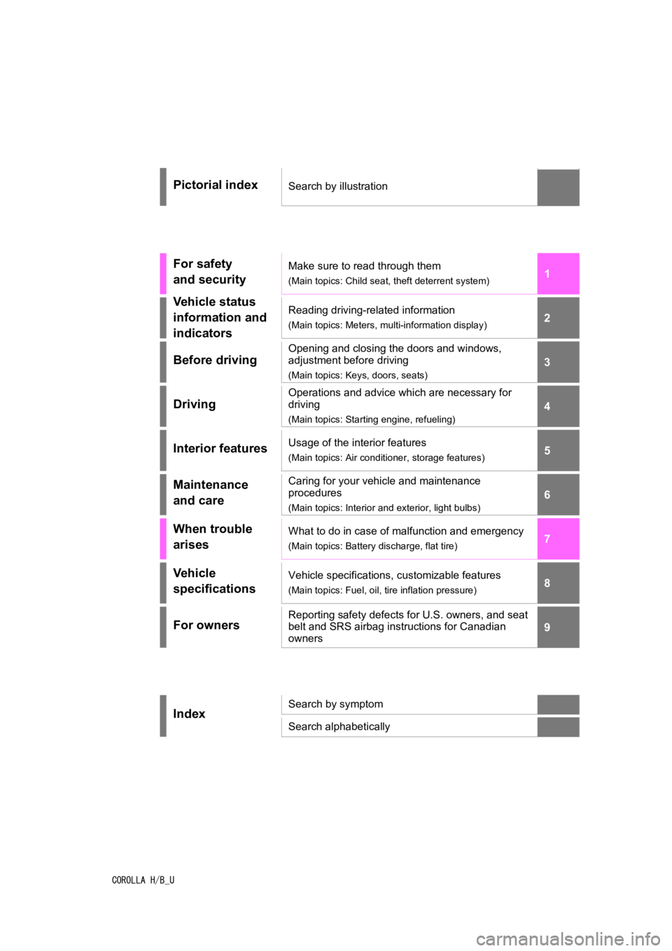
Pictorial indexSearch by illustration
For safety
and securityMake sure to read through them
(Main topics: Child seat, theft deterrent system)
Vehicle status
information and
indicatorsReading driving-related information
(Main topics: Meters, multi-information display)
Before driving
Opening and closing the doors and windows,
adjustment before driving
(Main topics: Keys, doors, seats)
Driving
Operations and advice which are necessary for
driving
(Main topics: Starting engine, refueling)
Interior featuresUsage of the interior features
(Main topics: Air conditioner, storage features)
Maintenance
and careCaring for your vehicle and maintenance
procedures
(Main topics: Interior and exterior, light bulbs)
When trouble
arisesWhat to do in case of malfunction and emergency
(Main topics: Battery discharge, flat tire)
Vehicle
specificationsVehicle specifications, customizable features
(Main topics: Fuel, oil, tire inflation pressure)
For ownersReporting safety defects for U.S. owners, and seat
belt and SRS airbag instructions for Canadian
owners
IndexSearch by symptom
Search alphabetically
Page 2 of 436
2TABLE OF CONTENTS
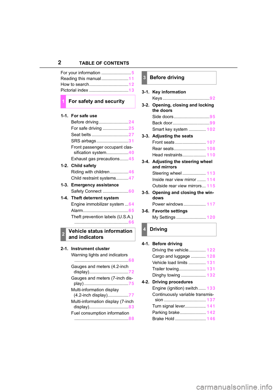
For your information ........................5
Reading this manual ...................... 11
How to search ................................ 12
Pictorial index ................................ 13
1-1. For safe use Before driving ........................ 24
For safe driving ..................... 25
Seat belts .............................. 27
SRS airbags .......................... 31
Front passenger occupant clas- sification system.................. 40
Exhaust gas precautions....... 45
1-2. Child safety Riding with children ............... 46
Child restraint systems .......... 47
1-3. Emergency assistance Safety Connect ..................... 60
1-4. Theft deterrent system Engine immobilizer system ... 64
Alarm ..................................... 65
Theft prevention labels (U.S.A.) ............................................ 66
2-1. Instrument cluster Warning lights and indicators............................................ 68
Gauges and meters (4.2-inch display)................................ 72
Gauges and meters (7-inch dis- play) .................................... 75
Multi-information display (4.2-inch display)................. 77
Multi-information display (7-inch display)................................ 83
Fuel consumption information ............................................ 883-1. Key information
Keys ...................................... 92
3-2. Opening, closing and locking the doors
Side doors ............................. 95
Back door .............................. 99
Smart key system .............. 102
3-3. Adjusting the seats Front seats ......................... 107
Rear seats.......................... 108
Head restraints................... 110
3-4. Adjusting the steering wheel and mirrors
Steering wheel ................... 113
Inside rear view mirror ....... 114
Outside rear view mirrors ... 115
3-5. Opening and closing the win- dows
Power windows .................. 117
3-6. Favorite settings My Settings ........................ 120
4-1. Before driving Driving the vehicle.............. 122
Cargo and luggage ............ 128
Vehicle load limits .............. 131
Trailer towing...................... 131
Dinghy towing .................... 132
4-2. Driving procedures Engine
(ignition) switch ...... 133
Continuously variable transmis- sion .................................. 137
Turn signal lever................. 141
Parking brake ..................... 142
Brake Hold ......................... 146
1For safety and security
2Vehicle status information
and indicators
3Before driving
4Driving
Page 15 of 436
15Pictorial index
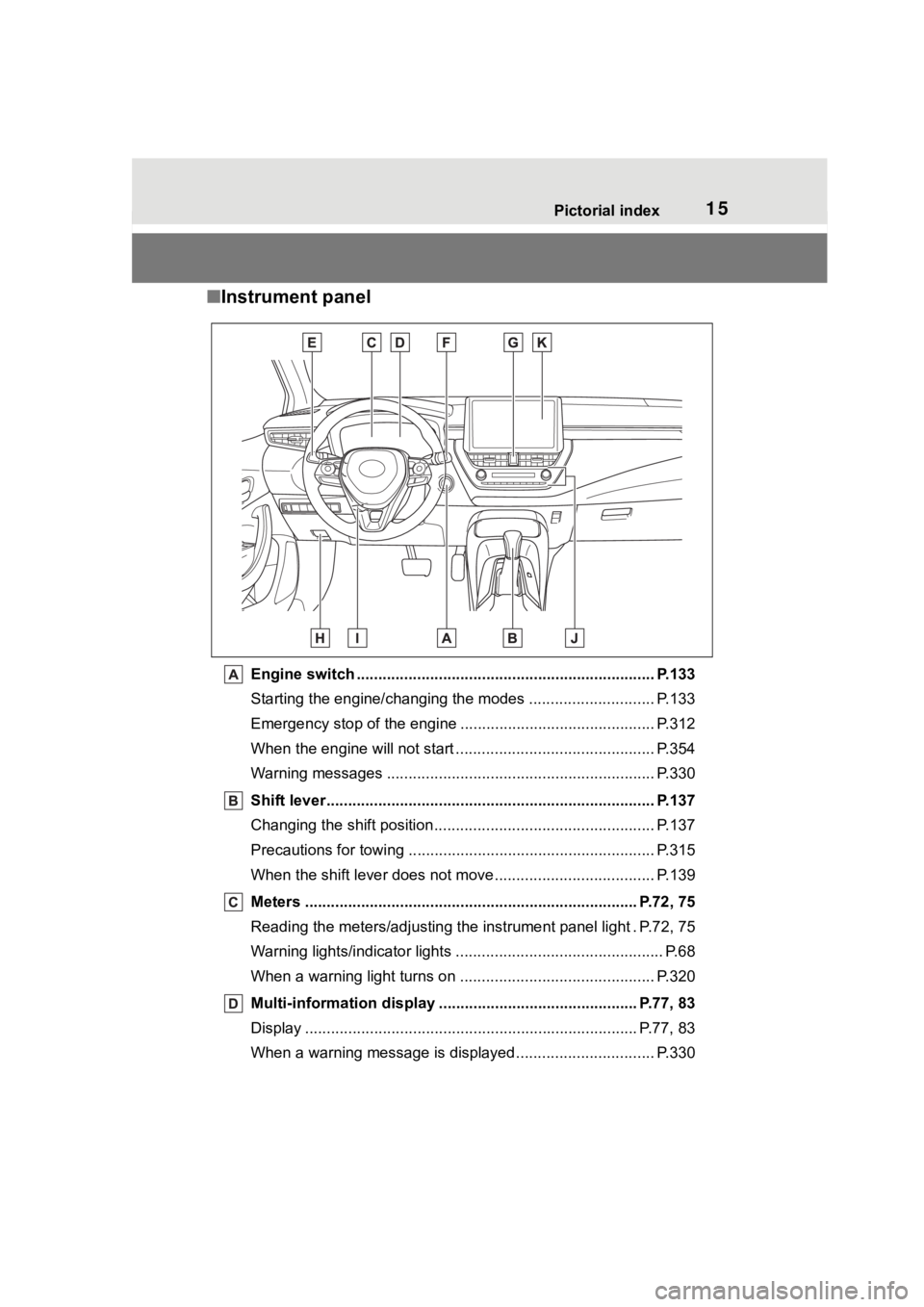
■Instrument panel
Engine switch ..................................................................... P.133
Starting the engine/changing the modes ......................... .... P.133
Emergency stop of the engin e ............................................. P.312
When the engine will not start ................................. ............. P.354
Warning messages ............................................... ............... P.330
Shift lever.................................................... ........................ P.137
Changing the shift position.................................... ............... P.137
Precautions for towing .. ....................................... ................ P.315
When the shift lever does not move............................. ........ P.139
Meters ............................................................................. P.72, 75
Reading the meters/adjusting the instrument panel light . P.72, 7 5
Warning lights/indicator lights ................................ ................ P.68
When a warning light turns on .................................. ........... P.320
Multi-information display . ............................................. P.77, 83
Display ........................................................ ..................... P.77, 83
When a warning message is displayed ............................ .... P.330
Page 56 of 436
561-2. Child safety
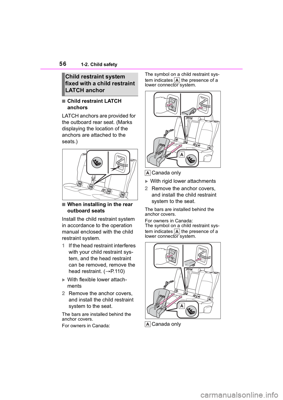
■Child restraint LATCH
anchors
LATCH anchors are provided for
the outboard rear seat. (Marks
displaying the location of the
anchors are attached to the
seats.)
■When installing in the rear
outboard seats
Install the child restraint system
in accordance to the operation
manual enclosed with the child
restraint system.
1 If the head restraint interferes
with your child restraint sys-
tem, and the head restraint
can be removed, remove the
head restraint. ( P.110)
With flexible lower attach-
ments
2 Remove the anchor covers,
and install the child restraint
system to the seat.
The bars are ins talled behind the
anchor covers.
For owners in Canada: The symbol on a child restraint sys-
tem indicates the presence of a
lower connector system.
Canada only
With rigid lower attachments
2 Remove the anchor covers,
and install the child restraint
system to the seat.
The bars are installed behind the
anchor covers.
For owners in Canada:
The symbol on a child restraint sys-
tem indicates the presence of a
lower connector system.
Canada only
Child restraint system
fixed with a child restraint
LATCH anchor
Page 67 of 436
67
2
2
Vehicle status information and indicators
Vehicle status informationand indicators
.2-1. Instrument cluster
Warning lights and indica-tors ............................... 68
Gauges and meters (4.2-inch display) .......... 72
Gauges and meters (7-inch display) ......................... 75
Multi-information display (4.2-inch display) .......... 77
Multi-information display (7-inch display) ............. 83
Fuel consumption informa- tion ............................... 88
Page 68 of 436
682-1. Instrument cluster
2-1.Instrument cluster
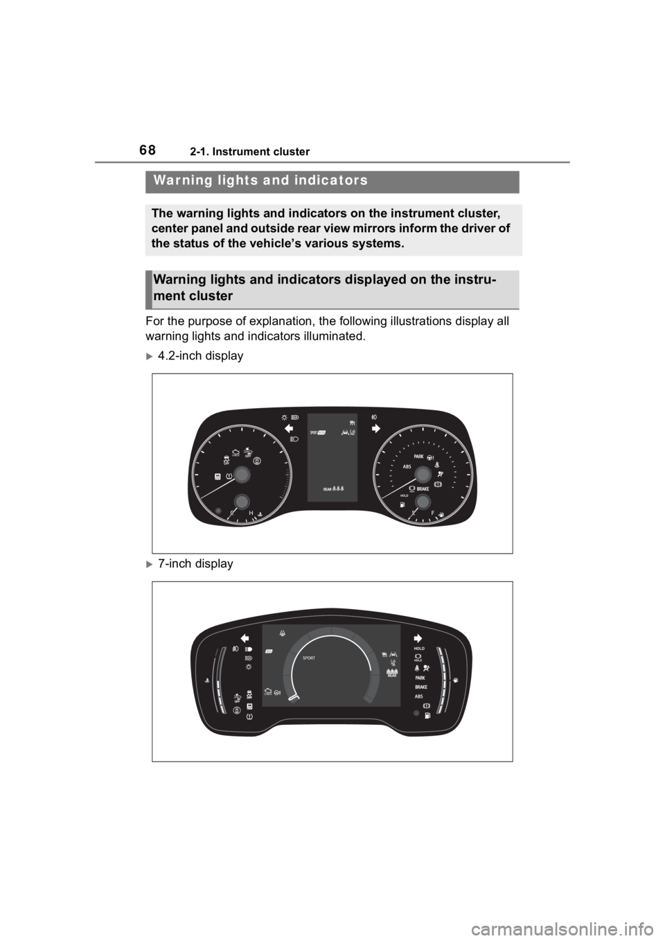
For the purpose of explanation, the following illustrations display all
warning lights and indicators illuminated.
4.2-inch display
7-inch display
War ning lights and indicators
The warning lights and indicators on the instrument cluster,
center panel and outside rear view mirrors inform the driver of
the status of the vehicle’s various systems.
Warning lights and indicators displayed on the instru-
ment cluster
Page 70 of 436
702-1. Instrument cluster
*1: These lights come on when the engine switch is turned to ON to
indicate that a system check is
being performed. They will turn
off after the engine is started, or
after a few seconds. There may
be a malfunction in a system if
the lights do not come on, or turn
off. Have the vehicle inspected
by your Toyota dealer.
*2: This light illuminates on the multi-information display.
*3: 4.2-inch display.
*4: 7-inch display.
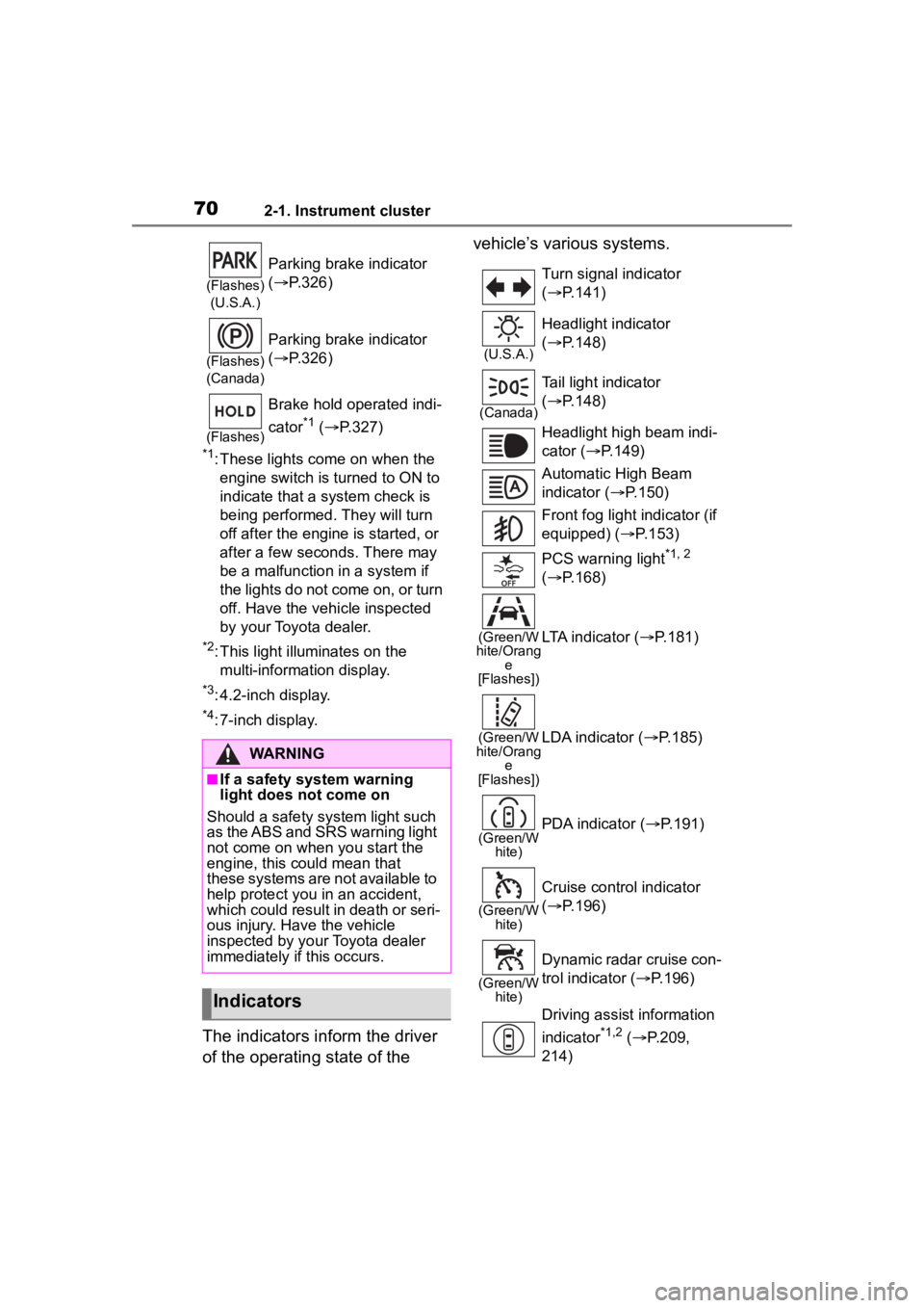
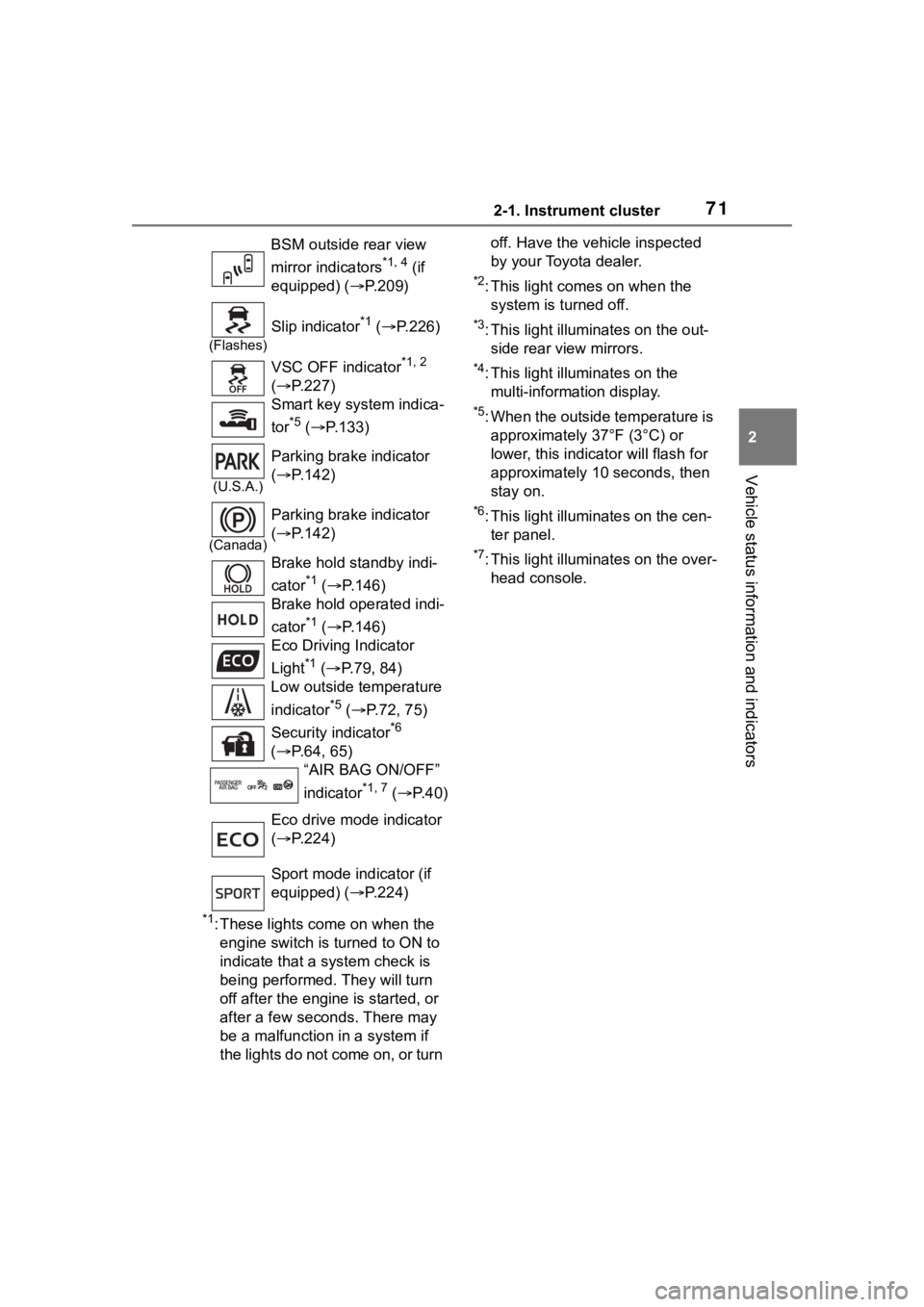
The indicators inform the driver
of the operating state of the vehicle’s various systems.
(Flashes)
(U.S.A.)
Parking brake indicator
( P.326)
(Flashes)
(Canada)
Parking brake indicator
( P.326)
(Flashes)
Brake hold operated indi-
cator
*1 ( P.327)
WARNING
■If a safety system warning
light does not come on
Should a safety system light such
as the ABS and SRS warning light
not come on when you start the
engine, this could mean that
these systems are not available to
help protect you in an accident,
which could result in death or seri-
ous injury. Have the vehicle
inspected by your Toyota dealer
immediately if this occurs.
Indicators
Turn signal indicator
( P.141)
(U.S.A.)
Headlight indicator
( P.148)
(Canada)
Tail light indicator
( P.148)
Headlight high beam indi-
cator ( P.149)
Automatic High Beam
indicator ( P.150)
Front fog light indicator (if
equipped) ( P.153)
PCS warning light
*1, 2
( P.168)
(Green/W
hite/Orang e
[Flashes])LTA indicator ( P.181)
(Green/W
hite/Orang e
[Flashes])LDA indicator ( P.185)
(Green/W
hite)PDA indicator ( P.191)
(Green/W
hite)
Cruise control indicator
( P.196)
(Green/W
hite)
Dynamic radar cruise con-
trol indicator ( P.196)
Driving assist information
indicator
*1,2 ( P.209,
214)
Page 71 of 436
712-1. Instrument cluster
2
Vehicle status information and indicators
*1: These lights come on when the engine switch is turned to ON to
indicate that a system check is
being performed. They will turn
off after the engine is started, or
after a few seconds. There may
be a malfunction in a system if
the lights do not come on, or turn off. Have the vehicle inspected
by your Toyota dealer.
*2: This light comes on when the
system is turned off.
*3: This light illuminates on the out-side rear view mirrors.
*4: This light illuminates on the multi-information display.
*5: When the outside temperature is approximately 37°F (3°C) or
lower, this indicator will flash for
approximately 10 seconds, then
stay on.
*6: This light illuminates on the cen-ter panel.
*7: This light illuminates on the over-head console.
BSM outside rear view
mirror indicators
*1, 4 (if
equipped) ( P.209)
(Flashes)
Slip indicator*1 ( P.226)
VSC OFF indicator
*1, 2
( P.227)
Smart key system indica-
tor
*5 ( P.133)
(U.S.A.)
Parking brake indicator
( P.142)
(Canada)
Parking brake indicator
( P.142)
Brake hold standby indi-
cator
*1 ( P.146)
Brake hold operated indi-
cator
*1 ( P.146)
Eco Driving Indicator
Light
*1 ( P.79, 84)
Low outside temperature
indicator
*5 ( P.72, 75)
Security indicator
*6
( P.64, 65)
“AIR BAG ON/OFF”
indicator
*1, 7 ( P. 4 0 )
Eco drive mode indicator
( P.224)
Sport mode indicator (if
equipped) ( P.224)
Page 72 of 436
722-1. Instrument cluster
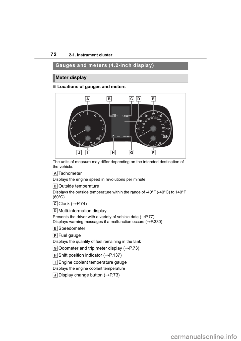
■Locations of gauges and meters
The units of measure may differ depending on the intended destination of
the vehicle.
Tachometer
Displays the engine speed in revolutions per minute
Outside temperature
Displays the outside temperature within the range of -40°F (-40 °C) to 140°F
(60°C)
Clock ( P. 7 4 )
Multi-information display
Presents the driver with a variety of vehicle data (P.77)
Displays warning messages if a malfunction occurs (P.330)
Speedometer
Fuel gauge
Displays the quantity of fu el remaining in the tank
Odometer and trip meter display ( P.73)
Shift position indicator ( P.137)
Engine coolant temperature gauge
Displays the engine c oolant temperature
Display change button ( P.73)
Gauges and meters (4.2-inch display)
Meter display
Page 73 of 436
732-1. Instrument cluster
2
Vehicle status information and indicators
■Outside temperature display
●In the following situations, the cor-
rect outside tempe rature may not
be displayed, or the display may
take longer than normal to
change:
• When stopped, or driving at low
speeds (less than 12 mph [20
km/h])
• When the outside temperature
has changed suddenly (at the
entrance/exit of a garage, tunnel,
etc.)
●When “--” or “E” is displayed, the
system may be malfunctioning.
Take your vehicle to your Toyota
dealer.
■Liquid crystal display
P. 7 8
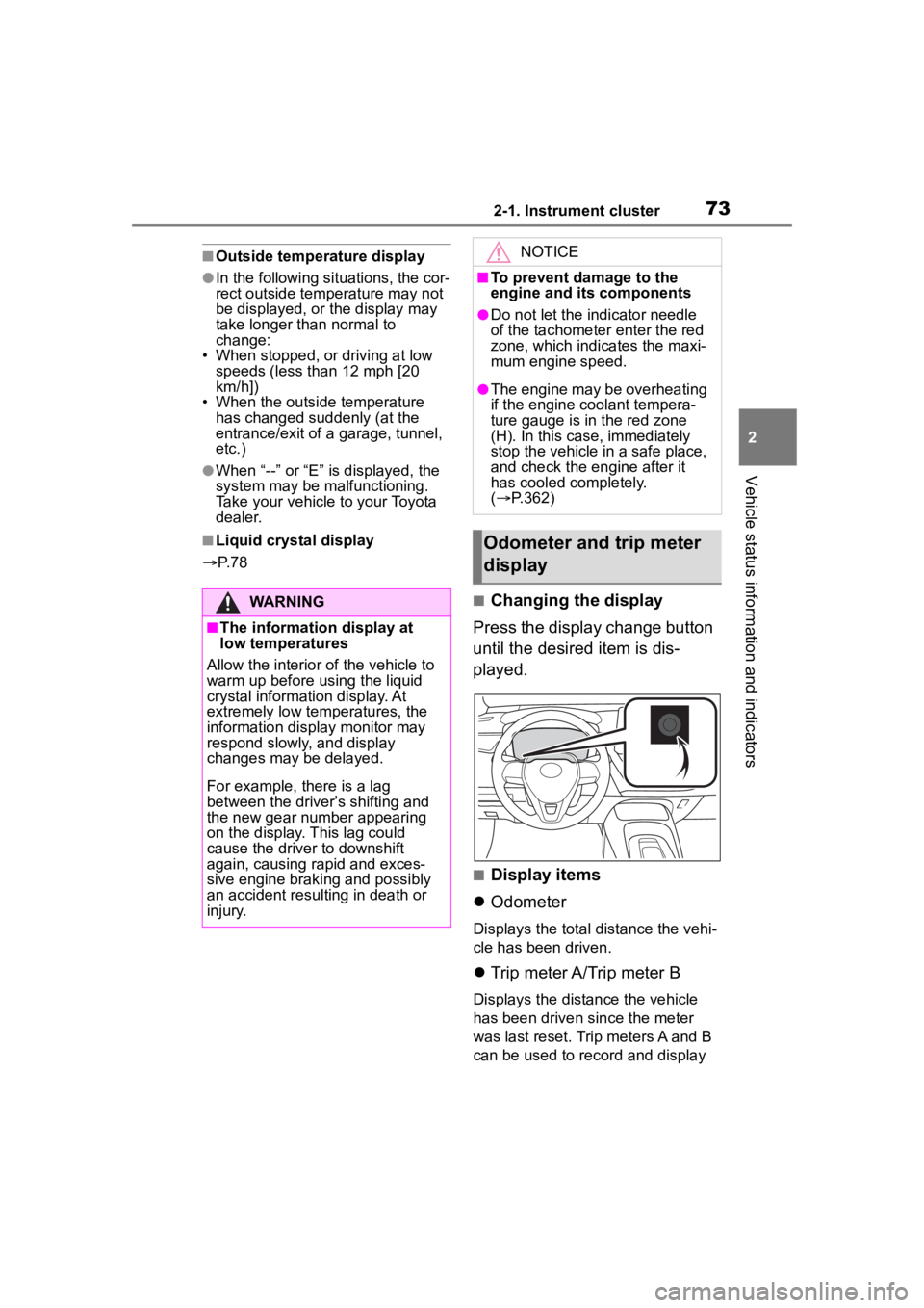
■Changing the display
Press the display change button
until the desired item is dis-
played.
■Display items
Odometer
Displays the total distance the vehi-
cle has been driven.
Trip meter A/Trip meter B
Displays the distance the vehicle
has been driven since the meter
was last reset. Trip meters A and B
can be used to record and display
WARNING
■The information display at
low temperatures
Allow the interior of the vehicle to
warm up before u sing the liquid
crystal informat ion display. At
extremely low temperatures, the
information display monitor may
respond slowly, and display
changes may be delayed.
For example, there is a lag
between the driver’s shifting and
the new gear number appearing
on the display. This lag could
cause the driver to downshift
again, causing rapid and exces-
sive engine braking and possibly
an accident resulting in death or
injury.
NOTICE
■To prevent damage to the
engine and its components
●Do not let the indicator needle
of the tachometer enter the red
zone, which indicates the maxi-
mum engine speed.
●The engine may be overheating
if the engine coolant tempera-
ture gauge is in the red zone
(H). In this case, immediately
stop the vehicle in a safe place,
and check the engine after it
has cooled completely.
( P.362)
Odometer and trip meter
display