TOYOTA GR YARIS 2023 Owners Manual
Manufacturer: TOYOTA, Model Year: 2023, Model line: GR YARIS, Model: TOYOTA GR YARIS 2023Pages: 470, PDF Size: 113.17 MB
Page 91 of 470
89
2
Owner's Manual_Europe_M52P63_en
2-1. Instrument cluster
Vehicle status information and indicators
●If a warning message is displayed,
operation of the settings display will be suspended.
Stop & Start system operation
time (after start)/status notifica-
tion
Displays the current amount of time the
engine has been stopped by the opera-
tion of the Stop & Start system.
Also shows the status of the Stop &
Start system with a pop-up display.
( P.196)
Stop & Start system settings
The length of time of the Stop & Start
system will operate when the “A/C”
switch of the air conditioning system is
on can be set to 2 different levels in
of the multi-information display.
( P.196)
WARNING
■Cautions during setting up the
display
If the engine is running when chang- ing the display settings, ensure that
the vehicle is parked in a place with adequate ventilation. In a closed area such as a garage, exhaust gases
including harmful carbon monoxide (CO) may collect and enter the vehi-cle. This may lead to death or a seri-
ous health hazard.
NOTICE
■During setting up the display
To prevent battery discharge, ensure that the engine is running while set-ting up the display features.
Stop & Start system infor-
mation
Page 92 of 470
90
Owner's Manual_Europe_M52P63_en
2-1. Instrument cluster
*: If equipped
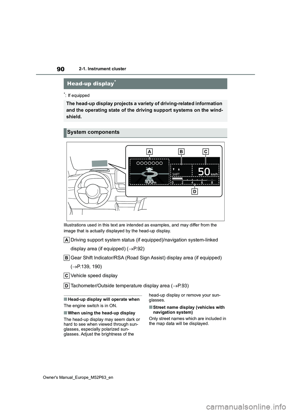
Illustrations used in this text are intended as examples, and m ay differ from the
image that is actually displayed by the head-up display.
Driving support system status (if equipped)/navigation system-l inked
display area (if equipped) ( P. 9 2 )
Gear Shift Indicator/RSA (Road Sign Assist) display area (if eq uipped)
( P.139, 190)
Vehicle speed display
Tachometer/Outside temperature display area ( P. 9 3 )
■Head-up display will operate when
The engine switch is in ON.
■When using the head-up display
The head-up display may seem dark or hard to see when viewed through sun-glasses, especially polarized sun-
glasses. Adjust the brightness of the
head-up display or remove your sun- glasses.
■Street name display (vehicles with
navigation system)
Only street names which are included in the map data will be displayed.
Head-up display*
The head-up display projects a variety of driving-related infor mation
and the operating state of the d riving support systems on the wind-
shield.
System components
Page 93 of 470
91
2
Owner's Manual_Europe_M52P63_en
2-1. Instrument cluster
Vehicle status information and indicators
Select on the multi-information
display ( P.359) and then “HUD
Main”.
■Enabling/disabling the head-
up display
Press the meter control switch
to enable/disable the head-up dis-
play.
■Changing the head-up display
settings
Press and hold the meter con-
trol switch to change the following
settings:
Brightness and vertical position
of the head-up display
Select to adjust the brightness or verti-
cal position of the head-up display.
Display content
Select to change the display between
the following:
• No content
• Tachometer
Select to enable/disable the fol-
lowing items:
• Route guidance to destination (if
equipped)
• Driving support system display (if
equipped)
• Compass (heading-up display) (if
equipped)
• Audio system operation status (if
equipped)
Display angle
Select to adjust the angle of the head-
up display.
WARNING
■When using the head-up display
●Check that the position and bright-
ness of the head-up display image does not interfere with safe driving. Incorrect adjustment of the image’s
position or brightness may obstruct the driver’s view and lead to an accident, resulting in death or seri-
ous injury.
●Do not continuously look at the
head-up display while driving as you may fail to see pedestrians, objects on the road, etc., ahead of
the vehicle.
NOTICE
■Head-up display projector
●Do not place any drinks near the head-up display projector. If the projector gets wet, electrical mal-
functions may result.
●Do not place anything on or put stickers onto the head-up display projector.
Doing so could interrupt head-up display indications.
●Do not touch the inside of the head-up display projector or thrust sharp edges or the like into the projector.
Doing so could cause mechanical malfunctions.
Using the head-up display
Page 94 of 470
92
Owner's Manual_Europe_M52P63_en
2-1. Instrument cluster
■Enabling/disabling of the head-up display
If the head-up display is disabled, it will remain disabled when the engine switch is turned off then back to ON.
■Display brightness
The brightness of the head-up display
can be adjusted on of the multi-
information display. Also, it is automati-
cally adjusted according to the ambient
brightness.
■Driving support system status
display
Displays the operational status of
the following systems:
Dynamic radar cruise control (if
equipped) ( P.179)
LTA (Lane Tracing Assist) (if
equipped) ( P.170)
Details of content displayed on the
head-up display may differ from that
displayed on the multi-information dis-
play. For details, refer to the explana-
tion of each system.
■Navigation system-linked dis-
play area (if equipped)
Displays the following items which
are linked to the navigation system:
Street name
Route guidance to destination
Compass (heading-up display)
Pop-up displays for the following
systems will be displayed when
necessary:
■Driving support systems
Displays a warning/sugges-
tion/advice message or the operat-
ing state of a relevant system.
PCS (Pre-Collision System) (if
equipped) ( P.158)
LTA (Lane Tracing Assist) (if
equipped) ( P.170)
Brake Override System
( P.126)
Details of content displayed on the
head-up display may differ from that
displayed on the multi-information dis-
play. For details, refer to the explana-
tion of each system.
WARNING
■Caution for changing settings of
the head-up display
If the engine is running when chang- ing the display settings, ensure that
the vehicle is parked in a place with adequate ventilation. In a closed area such as a garage, exhaust gases
including harmful carbon monoxide (CO) may collect and enter the vehi-cle. This may lead to death or a seri-
ous health hazard.
NOTICE
■When changing the settings of the head-up display
To prevent battery discharge, ensure
that the engine is running while changing the settings of the head-up display.
Driving support system sta-
tus/navigation system-
linked display area
Pop-up display
Page 95 of 470
93
2
Owner's Manual_Europe_M52P63_en
2-1. Instrument cluster
Vehicle status information and indicators
■ icon
Displayed when a warning mes-
sage is displayed on the multi-infor-
mation display. ( P.321)
■Warning message
Some warning messages are dis-
played when necessary, according
to certain conditions.
Details of content displayed on the
head-up display may differ from that
displayed on the multi-information dis-
play.
■Audio system operation status
(if equipped)
Displayed when an audio remote
control switch on the steering wheel
is operated.
■Hands-free system status (if
equipped)
Displayed when the hands-free
system is operated.
■When a pop-up display is displayed
When a pop-up display is displayed, a current display may no longer be dis-
played. In this case, the display will return after the pop-up display disap-pears.
■Tachometer
Displays the engine speed in revo-
lutions per minute.
■Outside temperature display
Displayed when the engine switch
is turned to ON or when the low
outside temperature indicator is
flashing.
■Outside temperature display
●When the ambient temperature is
approximately 3°C (37°F) or lower, the low outside temperature indicator will flash for approximately 10 seconds
and the outside temperature display will turn off. In this case, the display will be displayed again when the out-
side temperature becomes approxi- mately 5°C (41°F) or higher.
●In the following situations, the correct outside temperature may not be dis-played, or the display may take longer
than normal to change: • When stopped, or driving at low speeds (less than 25 km/h [16 mph])
• When the outside temperature has changed suddenly (at the entrance/exit of a garage, tunnel, etc.)
●When “--” or “E” is displayed, the sys-tem may be malfunctioning. Take your
vehicle to any authorized Toyota retailer or Toyota authorized repairer, or any reliable repairer.
Tachometer/Outside tem-
perature display
Page 96 of 470
94
Owner's Manual_Europe_M52P63_en
2-1. Instrument cluster
*: If equipped
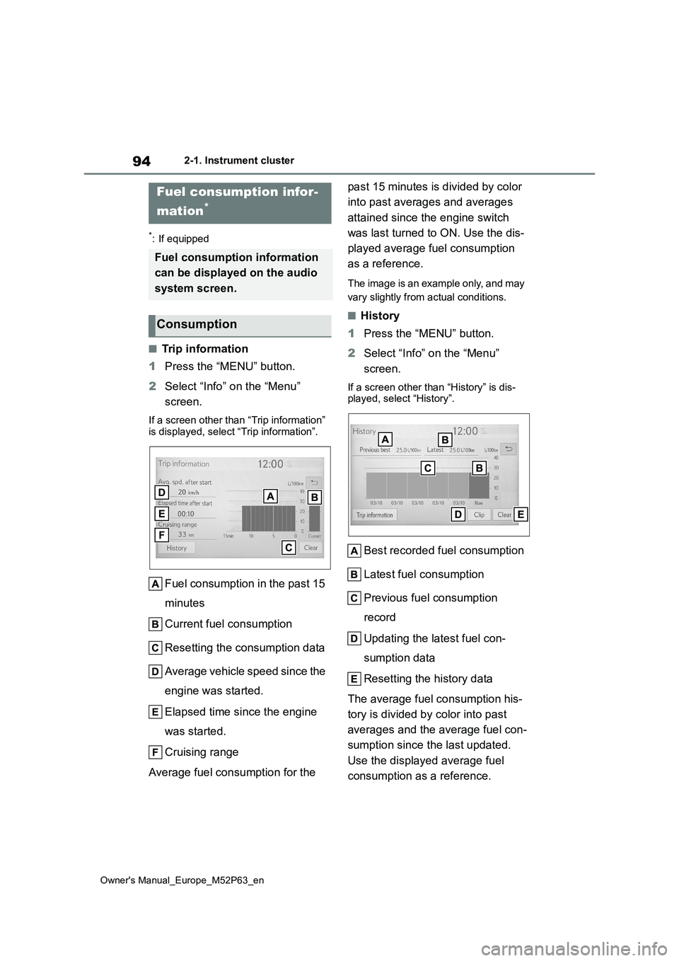
■Trip information
1 Press the “MENU” button.
2 Select “Info” on the “Menu”
screen.
If a screen other than “Trip information” is displayed, select “Trip information”.
Fuel consumption in the past 15
minutes
Current fuel consumption
Resetting the consumption data
Average vehicle speed since the
engine was started.
Elapsed time since the engine
was started.
Cruising range
Average fuel consumption for the
past 15 minutes is divided by color
into past averages and averages
attained since the engine switch
was last turned to ON. Use the dis-
played average fuel consumption
as a reference.
The image is an example only, and may
vary slightly from actual conditions.
■History
1 Press the “MENU” button.
2 Select “Info” on the “Menu”
screen.
If a screen other than “History” is dis- played, select “History”.
Best recorded fuel consumption
Latest fuel consumption
Previous fuel consumption
record
Updating the latest fuel con-
sumption data
Resetting the history data
The average fuel consumption his-
tory is divided by color into past
averages and the average fuel con-
sumption since the last updated.
Use the displayed average fuel
consumption as a reference.
Fuel consumption infor-
mation*
Fuel consumption information
can be displayed on the audio
system screen.
Consumption
Page 97 of 470
95
2
Owner's Manual_Europe_M52P63_en
2-1. Instrument cluster
Vehicle status information and indicators
The image is an example only, and may
vary slightly from actual conditions.
■Updating the history data
Update the latest fuel consumption by selecting “Clip” to measure the current
fuel consumption again.
■Resetting the data
The fuel consumption data can be deleted by selecting “Clear”.
■Cruising range
Displays the estimated maximum dis- tance that can be driven with the quan-tity of fuel remaining.
This distance is computed based on your average fuel consumption.As a result, the actual distance that can
be driven may differ from that displayed.
Page 98 of 470

96
Owner's Manual_Europe_M52P63_en
2-1. Instrument cluster
Page 99 of 470
3
97
Owner's Manual_Europe_M52P63_en
3
Before driving
Before driving
3-1. Key information
Keys.................................... 98
3-2. Opening, closing and locking
the doors
Side doors ........................ 101
Back door ......................... 104
Smart entry & start system 107
3-3. Adjusting the seats
Front seats........................ 112
Rear seats ........................ 114
Head restraints ................. 115
3-4. Adjusting the steering wheel
and mirrors
Steering wheel .................. 118
Inside rear view mirror ...... 119
Outside rear view mirrors . 120
3-5. Opening and closing the win-
dows
Power windows................. 122
Page 100 of 470
98
Owner's Manual_Europe_M52P63_en
3-1. Key information
3-1.Key info rmation
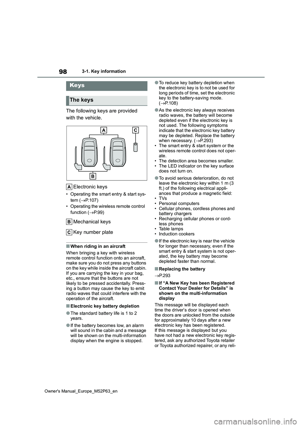
The following keys are provided
with the vehicle.
Electronic keys
• Operating the smart entry & start sys-
tem ( P.107)
• Operating the wireless remote control
function ( P. 9 9 )
Mechanical keys
Key number plate
■When riding in an aircraft
When bringing a key with wireless
remote control function onto an aircraft, make sure you do not press any buttons on the key while inside the aircraft cabin.
If you are carrying the key in your bag, etc., ensure that the buttons are not likely to be pressed accidentally. Press-
ing a button may cause the key to emit radio waves that could interfere with the operation of the aircraft.
■Electronic key battery depletion
●The standard battery life is 1 to 2 years.
●If the battery becomes low, an alarm will sound in the cabin and a message
will be shown on the multi-information display when the engine is stopped.
●To reduce key battery depletion when
the electronic key is to not be used for long periods of time, set the electronic key to the battery-saving mode.
( P.108)
●As the electronic key always receives
radio waves, the battery will become depleted even if the electronic key is not used. The following symptoms
indicate that the electronic key battery may be depleted. Replace the battery when necessary. ( P.293)
• The smart entry & start system or the wireless remote control does not oper-ate.
• The detection area becomes smaller. • The LED indicator on the key surface does not turn on.
●To avoid serious deterioration, do not leave the electronic key within 1 m (3
ft.) of the following electrical appli- ances that produce a magnetic field:•TVs
• Personal computers • Cellular phones, cordless phones and battery chargers
• Recharging cellular phones or cord- less phones• Table lamps
• Induction cookers
●If the electronic key is near the vehicle
for longer than necessary, even if the smart entry & start system is not oper-ated, the key battery may become
depleted faster than normal.
■Replacing the battery
P. 2 9 3
■If “A New Key has been Registered Contact Your Dealer for Details” is
shown on the multi-information display
This message will be displayed each
time the driver’s door is opened when the doors are unlocked from the outside for approximately 10 days after a new
electronic key has been registered. If this message is displayed but you have not had a new electronic key regis-
tered, ask any authorized Toyota retailer or Toyota authorized repairer, or any reli-
Keys
The keys