TOYOTA HIGHLANDER 2001 Service Repair Manual
Manufacturer: TOYOTA, Model Year: 2001, Model line: HIGHLANDER, Model: TOYOTA HIGHLANDER 2001Pages: 2572, PDF Size: 34.8 MB
Page 271 of 2572
2005 HIGHLANDER (EWD592U)
90
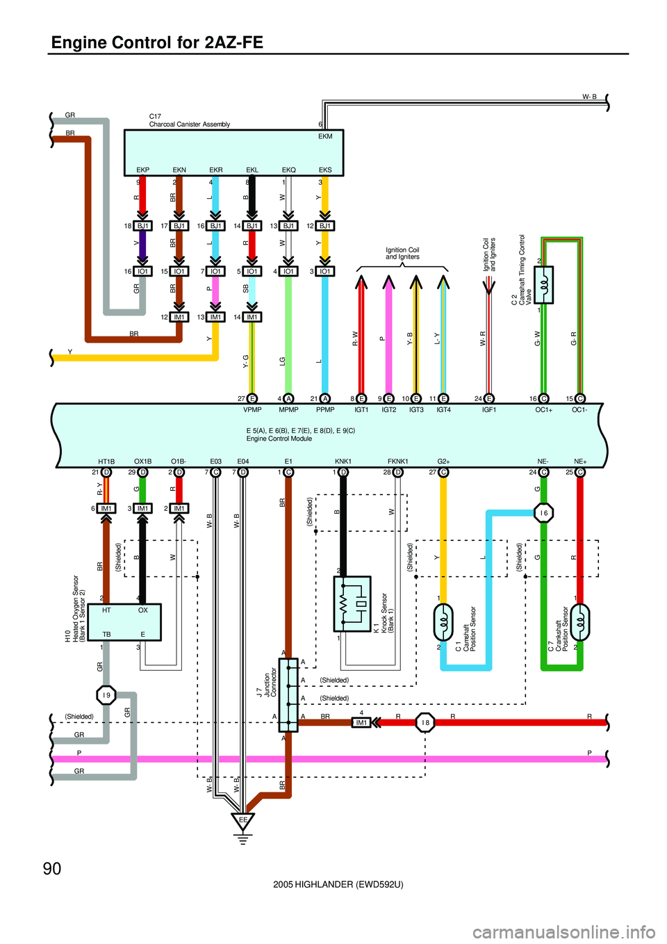
Engine Control for 2AZ-FE
15
27 13 IM1
Y- G
VPMP
IM14
J 7V
Y
14 16 IO1 3 IO1
WR
L
4IO1 BJ1 17
BR
IM1
L P BR
21
L
PPMPA A
MPMP
LG
4 IM1 12IO1 5 IO1
A
YGR
L BR
B
W
Y R
1 E BR
Y GR
BRC17
SB
1
W
D 7IO1
Ignition Coil
and Igniter s
93
Ignition Coil
and Igniters
28 O1B-13
Y (
Shielded)
1
R
8
IM1
G R- Y
W
14 18
H10
2 24
D 225 C 24 C 27 C 1D BJ1 BJ1(
Shielded)
4 2D 21 D29
3 1
B BR GR
BJ1 12 BJ1
(
Shielded)(
Shielded)
1
2 1
2
EE
G
GR
C 7 C 1
2B
R FKNK1
G
R
R 16
HT1BOX1B KNK1 G2+ NE- NE+
I 6 3IM1 6IM1IGT1
Y- B
IGF1
R- W
IGT2
P
IGT3
W- R
24 E 11 E 10 E 9E 8E BJ1
IGT4
L- Y
D 7 7C
W- B W- B
E03 E04 E1
C
BR
1 2
C 16 C15
G- W
G- R
OC1+ OC1-
C 2
P (
Shielded)
I 8 R BR A
A
A
A
A
P A(
Shielded)
(
Shielded)
BR W- B W- B
I 9
GR
GR
6W- B
E 5(
A)
, E 6(
B)
, E 7(
E)
, E 8(
D)
, E 9(
C)
Camshaft
Position Sensor
Camshaft Timing Control
Valve
Cr ankshaft
Position Sensor
Char coal Canister Assembly
Engi ne Control Module
Heated Oxygen Sensor
(
Bank 1 Sensor 2)
Junction
Connector
EKP EKN EKR EKL EKQ EKSEKM
HT OX
TB E
Knock Sensor
(
Bank 1) K 1
Page 272 of 2572

2005 HIGHLANDER (EWD592U)
91
S15
C 224L 3
B Y- B
O 1
A 292
BR
EPA2 EPA2
12
1+BM
W
B 6A27
VPA2
VPA2
W
210A
ETCS
3
23 A
MOPS
R 4M
A A
B
GY
17 31 24TRC-
C 10
17E 20A
STOP
1E 1
E 6
P 2
TRC+ 1 2
A
Y BR R- L
W- B W- B
E02 E01 PSW
25 STPB 19
EFNEO
V
2
2
E 16
NSW
B- R
E 17
STA
B
54
NP7. 5A
STARTER
EB2 3
E 7
B- R L B- R P 1
R
P PENG+
A30
R
ENG-
A
Skid Control ECU
with Actuator
W- B W- B
A 271
L
VCP2 VCP2
A 285
R
EPA EPA
A 226
B
VPA VPA
A 264
G
VCPA VCPA
B 27
B
IMI
B 26
V
IMO
EFIO EFII67
T1 4 2
IC1 4
R
4C
W- B
ME01
I 6
W- G
G 14C 21RL
L W- BW- B
NC- NC+ NT- NT+
W- GY R- WWT 3
C 6
D 261
2
D 34 35 D 2 1
27 D
E 5(
A)
, E 6(
B)
, E 7(
E)
, E 8(
D)
, E 9(
C) Fr om Power Source System (
See Page 62)
Accel Position Sensor
Counter Gear Speed
Sensor
Engi ne Control Module
Gen erat or
Oil Pressur e SWPark/Neutral
Position SW
Power Steering Oil
Pressure SW
Stop Light SW
Turbine Speed Sensor
Transponder Key Computer
Page 273 of 2572
2005 HIGHLANDER (EWD592U)
92
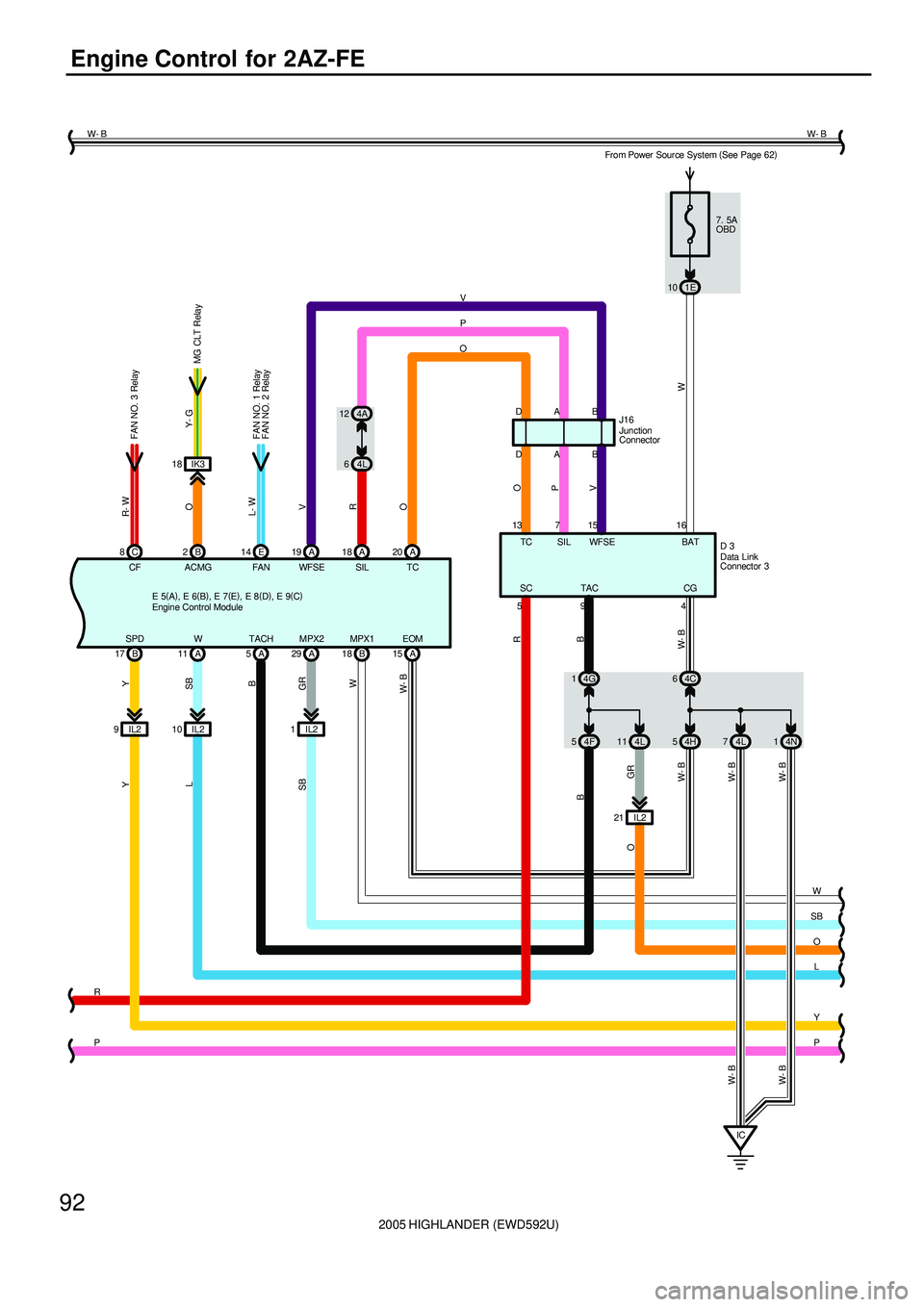
Engine Control for 2AZ-FE
O
L
Y
OGR
TAC
9
B
OP
V
18 IK3
FAN NO. 1 Relay
DJ16
W TC
5
O
V
D
13 7
SIL WFSEB
P
7. 5A
OBD
1E 10
A 18 A20 A 19
ACMG
O
B
4F 5B
IL2 10 IL2 95ATACH
R16
WFSE SIL TC
V
R
O
W SBY Y
L
15
SPD W
B 17 A11BAT
MG CLT Relay
A
A
B 2
5
SB
ICP 4L 74N1
R
SC
W- B
64C
W- B
W- B
CF
R- W
C 8
FAN
L- W
E 14
FAN NO. 3 Relay
4G 1
B
D 3
4CG
Y- G
EOM
A 15
W- B SB
1IL2MPX2
GR
A 29
4H 11 4L
IL2 21 4L 64A 12
W- B
W- B
W- B
MPX1
W
B 18
P W- BW- B
From Power Sour ce System (
See Page 62)
FAN NO. 2 Relay
E 5(
A)
, E 6(
B)
, E 7(
E)
, E 8(
D)
, E 9(
C)Data Link
Connector 3
Engine Control ModuleJunction
Connector
Page 274 of 2572
2005 HIGHLANDER (EWD592U)
93
O
L
Y
P5
W
Y
GR
IF3
A 10
B 6MPX2
MPX1
O
L 8
O
SBSBY
7
1IB2MPX1
MPX2
P 5 Y
8IB2
V
4A 5
4F 7
A 2 A 1B 1B2
IL2 12
V
114
MPD1
MPD2G 5G
B 2
A 9MPX+
MPX-A17
13E3J 12
(
*2) G
(
*3)
(
*2)R SB
R
BRBR
G Y
BR
BR
24
MPX122
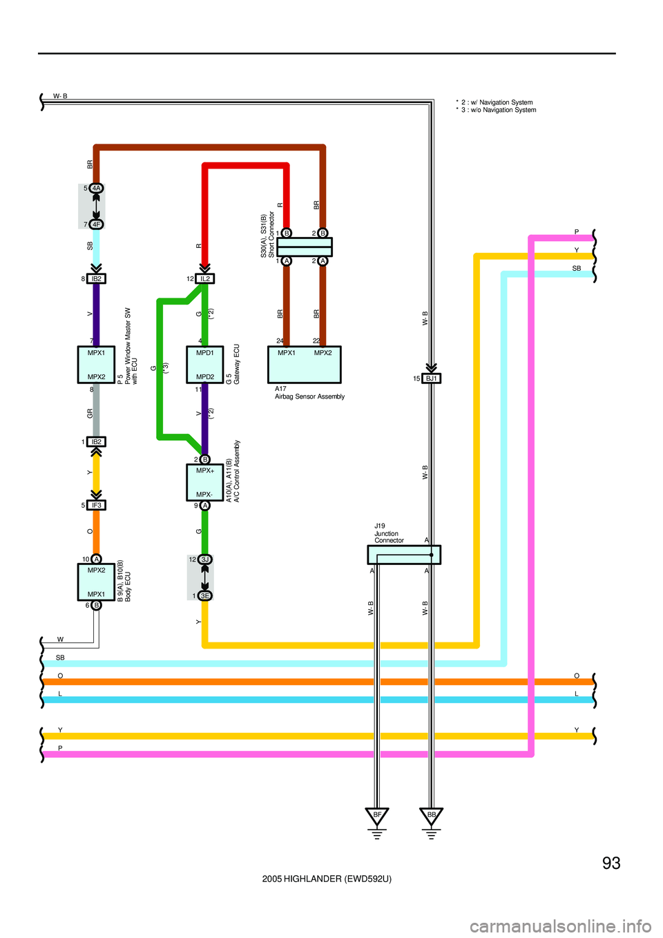
MPX2P * 2 : w/ Navigation System
* 3 : w/o Navigation System W- B
BB BF AAABJ1 15
W- B W- B W- B
W- B
J1 9
A10(
A)
, A11(
B) B 9(
A)
, B10(
B)
S30(
A)
, S31(
B) A/C Control Assembly
Airbag Sensor Assembly
Body ECU
Gat eway ECU
Ju nctio n
Connector
Power Window Master SW
with ECU
Short Connector
Page 275 of 2572
2005 HIGHLANDER (EWD592U)
94
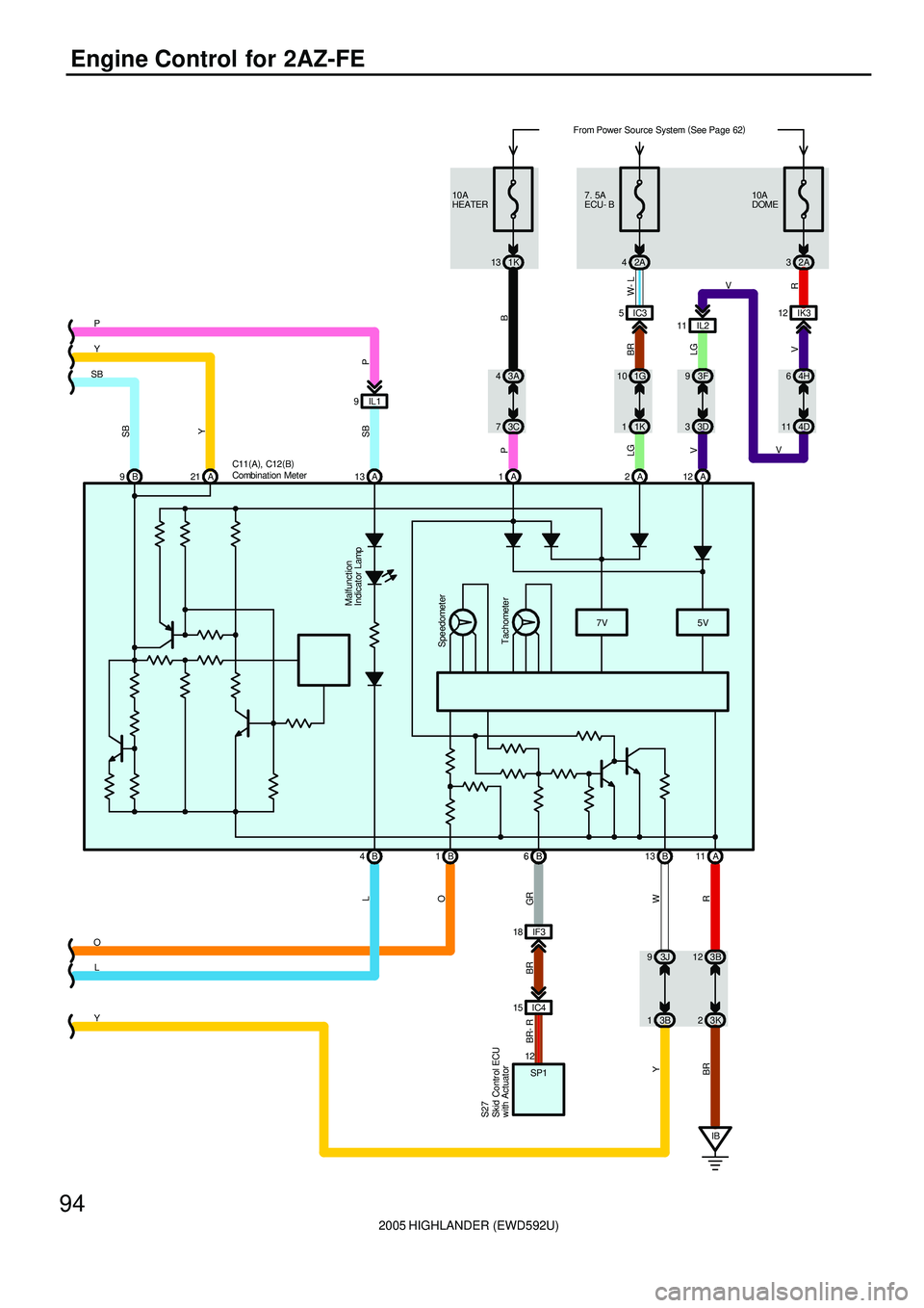
Engine Control for 2AZ-FE
W Y
93J
13B IF3 18
IC4 15
GR BR BR- R
12
SP1
OL
O
YL4B Y
SBP
P SB
IL1 9
A 13
Malfunction
Indicator Lamp
6B
SB
Y
IB 21 A 9BA 12 A 2 A
5V 7V
Tachometer Speedometer
B 13 1
B 6 B 1
R
11 A
3B 12
3K 2 11 IL2IK3 12
V V
VR
32A 10A
DOME
11 4D64H
LG V
33D 93F
BR W- L LGPB
73C 43A
11K 10 1G5IC3 7. 5A
ECU- B
2A 4 13 1K 10A
HEATER
BR
From Power Source System (
See Page 62)
Combination Meter C11(
A)
, C12(
B)
Skid Contr ol ECU
with Actuator S27
Page 276 of 2572
2005 HIGHLANDER (EWD592U)
95
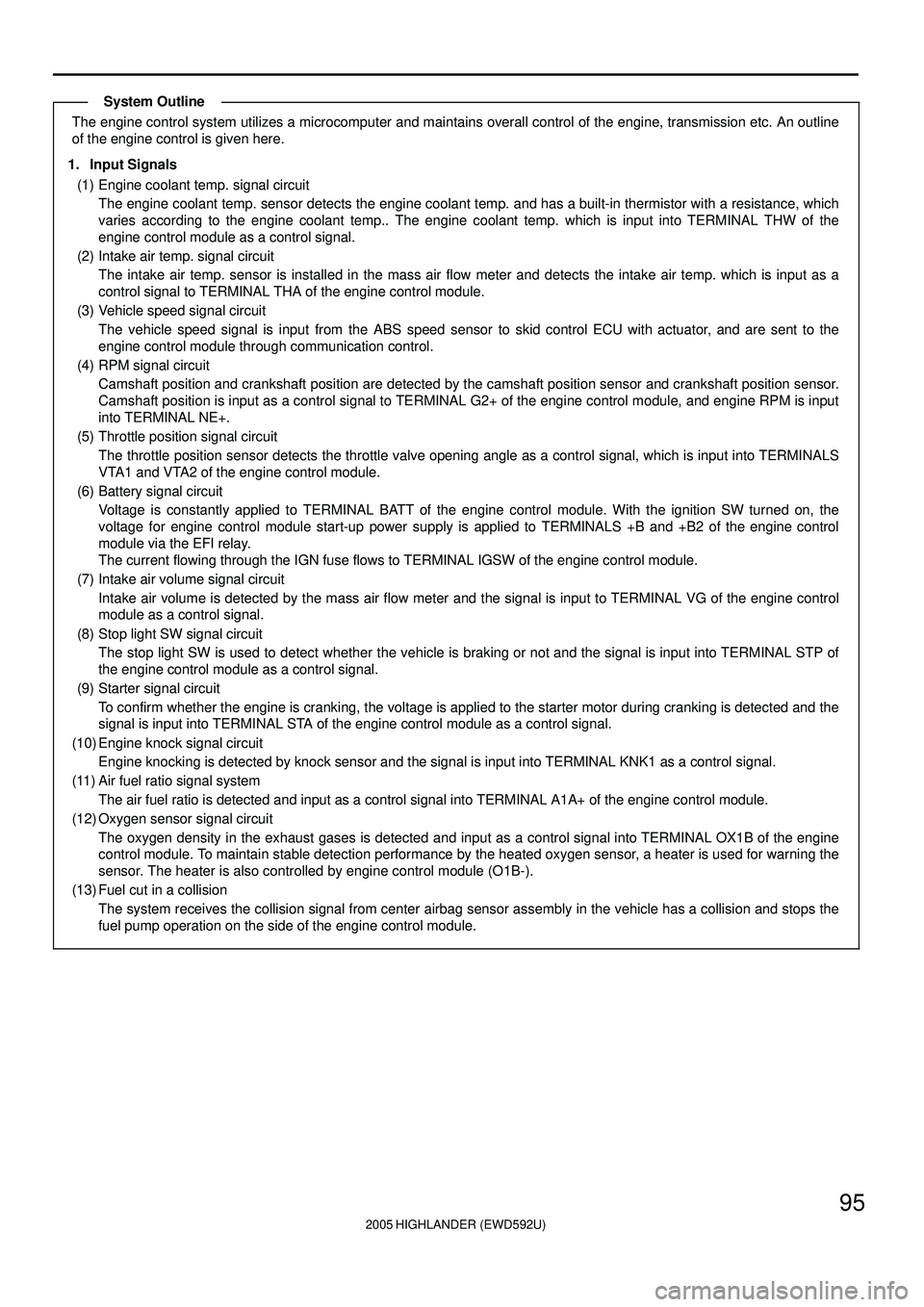
The engine control system utilizes a microcomputer and maintains overall control of the engine, transmission etc. An outline
of the engine control is given here.
1. Input Signals
(1) Engine coolant temp. signal circuit
The engine coolant temp. sensor detects the engine coolant temp. and has a built-in thermistor with a resistance, which
varies according to the engine coolant temp.. The engine coolant temp. which is input into TERMINAL THW of the
engine control module as a control signal.
(2) Intake air temp. signal circuit
The intake air temp. sensor is installed in the mass air flow meter and detects the intake air temp. which is input as a
control signal to TERMINAL THA of the engine control module.
(3) Vehicle speed signal circuit
The vehicle speed signal is input from the ABS speed sensor to skid control ECU with actuator, and are sent to the
engine control module through communication control.
(4) RPM signal circuit
Camshaft position and crankshaft position are detected by the camshaft position sensor and crankshaft position sensor.
Camshaft position is input as a control signal to TERMINAL G2+ of the engine control module, and engine RPM is input
into TERMINAL NE+.
(5) Throttle position signal circuit
The throttle position sensor detects the throttle valve opening angle as a control signal, which is input into TERMINALS
VTA1 and VTA2 of the engine control module.
(6) Battery signal circuit
Voltage is constantly applied to TERMINAL BATT of the engine control module. With the ignition SW turned on, the
voltage for engine control module start-up power supply is applied to TERMINALS +B and +B2 of the engine control
module via the EFI relay.
The current flowing through the IGN fuse flows to TERMINAL IGSW of the engine control module.
(7) Intake air volume signal circuit
Intake air volume is detected by the mass air flow meter and the signal is input to TERMINAL VG of the engine control
module as a control signal.
(8) Stop light SW signal circuit
The stop light SW is used to detect whether the vehicle is braking or not and the signal is input into TERMINAL STP of
the engine control module as a control signal.
(9) Starter signal circuit
To confirm whether the engine is cranking, the voltage is applied to the starter motor during cranking is detected and the
signal is input into TERMINAL STA of the engine control module as a control signal.
(10) Engine knock signal circuit
Engine knocking is detected by knock sensor and the signal is input into TERMINAL KNK1 as a control signal.
(11) Air fuel ratio signal system
The air fuel ratio is detected and input as a control signal into TERMINAL A1A+ of the engine control module.
(12) Oxygen sensor signal circuit
The oxygen density in the exhaust gases is detected and input as a control signal into TERMINAL OX1B of the engine
control module. To maintain stable detection performance by the heated oxygen sensor, a heater is used for warning the
sensor. The heater is also controlled by engine control module (O1B-).
(13) Fuel cut in a collision
The system receives the collision signal from center airbag sensor assembly in the vehicle has a collision and stops the
fuel pump operation on the side of the engine control module.
System Outline
Page 277 of 2572
2005 HIGHLANDER (EWD592U)
96
Engine Control for 2AZ-FE
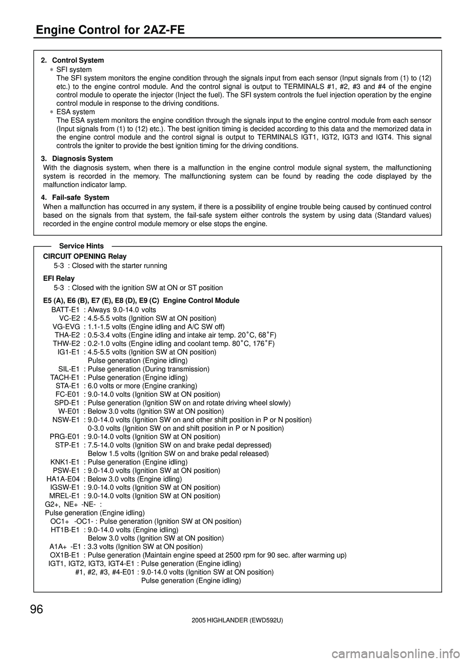
2. Control System
*SFI system
The SFI system monitors the engine condition through the signals input from each sensor (Input signals from (1) to (12)
etc.) to the engine control module. And the control signal is output to TERMINALS #1, #2, #3 and #4 of the engine
control module to operate the injector (Inject the fuel). The SFI system controls the fuel injection operation by the engine
control module in response to the driving conditions.
*ESA system
The ESA system monitors the engine condition through the signals input to the engine control module from each sensor
(Input signals from (1) to (12) etc.). The best ignition timing is decided according to this data and the memorized data in
the engine control module and the control signal is output to TERMINALS IGT1, IGT2, IGT3 and IGT4. This signal
controls the igniter to provide the best ignition timing for the driving conditions.
3. Diagnosis System
With the diagnosis system, when there is a malfunction in the engine control module signal system, the malfunctioning
system is recorded in the memory. The malfunctioning system can be found by reading the code displayed by the
malfunction indicator lamp.
4. Fail-safe System
When a malfunction has occurred in any system, if there is a possibility of engine trouble being caused by continued control
based on the signals from that system, the fail-safe system either controls the system by using data (Standard values)
recorded in the engine control module memory or else stops the engine.
CIRCUIT OPENING Relay
5-3 : Closed with the starter running
EFI Relay
5-3 : Closed with the ignition SW at ON or ST position
E5 (A), E6 (B), E7 (E), E8 (D), E9 (C) Engine Control Module
BATT-E1 : Always 9.0-14.0 volts
VC-E2 : 4.5-5.5 volts (Ignition SW at ON position)
VG-EVG : 1.1-1.5 volts (Engine idling and A/C SW off)
THA-E2 : 0.5-3.4 volts (Engine idling and intake air temp. 20°C, 68°F)
THW-E2 : 0.2-1.0 volts (Engine idling and coolant temp. 80°C, 176°F)
IG1-E1 : 4.5-5.5 volts (Ignition SW at ON position)
Pulse generation (Engine idling)
SIL-E1 : Pulse generation (During transmission)
TACH-E1 : Pulse generation (Engine idling)
STA-E1 : 6.0 volts or more (Engine cranking)
FC-E01 : 9.0-14.0 volts (Ignition SW at ON position)
SPD-E1 : Pulse generation (Ignition SW on and rotate driving wheel slowly)
W-E01 : Below 3.0 volts (Ignition SW at ON position)
NSW-E1 : 9.0-14.0 volts (Ignition SW on and other shift position in P or N position)
0-3.0 volts (Ignition SW on and shift position in P or N position)
PRG-E01 : 9.0-14.0 volts (Ignition SW at ON position)
STP-E1 : 7.5-14.0 volts (Ignition SW on and brake pedal depressed)
Below 1.5 volts (Ignition SW on and brake pedal released)
KNK1-E1 : Pulse generation (Engine idling)
PSW-E1 : 9.0-14.0 volts (Ignition SW at ON position)
HA1A-E04 : Below 3.0 volts (Engine idling)
IGSW-E1 : 9.0-14.0 volts (Ignition SW at ON position)
MREL-E1 : 9.0-14.0 volts (Ignition SW at ON position)
G2+, NE+ -NE- :
Pulse generation (Engine idling)
OC1+ -OC1- : Pulse generation (Ignition SW at ON position)
HT1B-E1 : 9.0-14.0 volts (Engine idling)
Below 3.0 volts (Ignition SW at ON position)
A1A+ -E1 : 3.3 volts (Ignition SW at ON position)
OX1B-E1 : Pulse generation (Maintain engine speed at 2500 rpm for 90 sec. after warming up)
IGT1, IGT2, IGT3, IGT4-E1 : Pulse generation (Engine idling)
#1, #2, #3, #4-E01 : 9.0-14.0 volts (Ignition SW at ON position)
Pulse generation (Engine idling)
Service Hints
Page 278 of 2572
2005 HIGHLANDER (EWD592U)
97
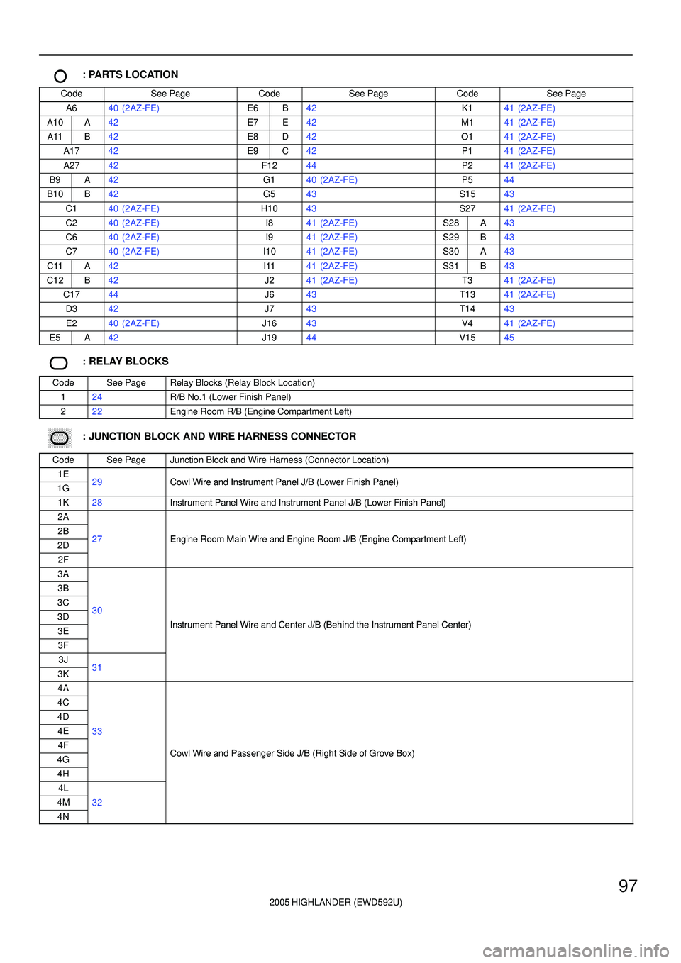
: PARTS LOCATION
CodeSee PageCodeSee PageCodeSee Page
A640 (2AZ-FE)E6B42K141 (2AZ-FE)
A10A42E7E42M141 (2AZ-FE)
A11B42E8D42O141 (2AZ-FE)
A1742E9C42P141 (2AZ-FE)
A2742F1244P241 (2AZ-FE)
B9A42G140 (2AZ-FE)P544
B10B42G543S1543
C140 (2AZ-FE)H1043S2741 (2AZ-FE)
C240 (2AZ-FE)I841 (2AZ-FE)S28A43
C640 (2AZ-FE)I941 (2AZ-FE)S29B43
C740 (2AZ-FE)I1041 (2AZ-FE)S30A43
C11A42I1141 (2AZ-FE)S31B43
C12B42J241 (2AZ-FE)T341 (2AZ-FE)
C1744J643T1341 (2AZ-FE)
D342J743T1443
E240 (2AZ-FE)J1643V441 (2AZ-FE)
E5A42J1944V1545
: RELAY BLOCKS
CodeSee PageRelay Blocks (Relay Block Location)
124R/B No.1 (Lower Finish Panel)
222Engine Room R/B (Engine Compartment Left)
������ ���: JUNCTION BLOCK AND WIRE HARNESS CONNECTOR
CodeSee PageJunction Block and Wire Harness (Connector Location)
1E29Cowl Wire and Instrument Panel J/B (Lower Finish Panel)1G29Cowl Wire and Instrument Panel J/B (Lower Finish Panel)
1K28Instrument Panel Wire and Instrument Panel J/B (Lower Finish Panel)
2A
2B27Engine Room Main Wire and Engine Room J/B (Engine Compartment Left)2D27Engine Room Main Wire and Engine Room J/B (Engine Compartment Left)
2F
3A
3B
3C303D30
Instrument Panel Wire and Center J/B (Behind the Instrument Panel Center)3EInstrument Panel Wire and Center J/B (Behind the Instrument Panel Center)
3F
3J313K31
4A
4C
4D
4E33
4FCowl Wire and Passenger Side J/B (Right Side of Grove Box)4GCowl Wire and Passenger Side J/B (Right Side of Grove Box)
4H
4L
4M32
4N
Page 279 of 2572
2005 HIGHLANDER (EWD592U)
98
Engine Control for 2AZ-FE
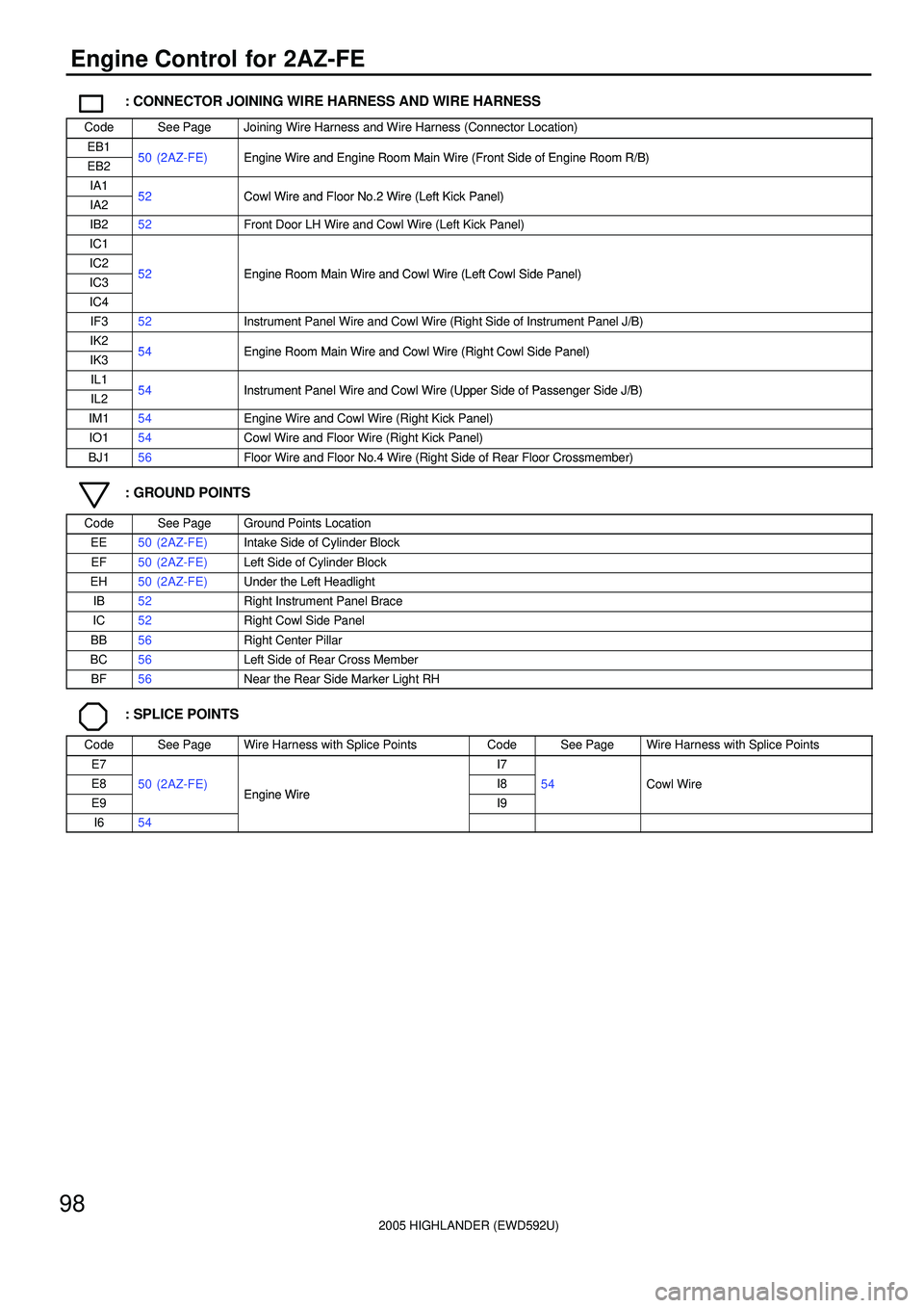
: CONNECTOR JOINING WIRE HARNESS AND WIRE HARNESS
CodeSee PageJoining Wire Harness and Wire Harness (Connector Location)
EB150 (2AZ FE)Engine Wire and Engine Room Main Wire (Front Side of Engine Room R/B)EB250 (2AZ-FE)Engine Wire and Engine Room Main Wire (Front Side of Engine Room R/B)
IA152Cowl Wire and Floor No 2 Wire (Left Kick Panel)IA252Cowl Wire and Floor No.2 Wire (Left Kick Panel)
IB252Front Door LH Wire and Cowl Wire (Left Kick Panel)
IC1
IC252Engine Room Main Wire and Cowl Wire (Left Cowl Side Panel)IC352Engine Room Main Wire and Cowl Wire (Left Cowl Side Panel)
IC4
IF352Instrument Panel Wire and Cowl Wire (Right Side of Instrument Panel J/B)
IK254Engine Room Main Wire and Cowl Wire (Right Cowl Side Panel)IK354Engine Room Main Wire and Cowl Wire (Right Cowl Side Panel)
IL154Instrument Panel Wire and Cowl Wire (Upper Side of Passenger Side J/B)IL254Instrument Panel Wire and Cowl Wire (Upper Side of Passenger Side J/B)
IM154Engine Wire and Cowl Wire (Right Kick Panel)
IO154Cowl Wire and Floor Wire (Right Kick Panel)
BJ156Floor Wire and Floor No.4 Wire (Right Side of Rear Floor Crossmember)
: GROUND POINTS
CodeSee PageGround Points Location
EE50 (2AZ-FE)Intake Side of Cylinder Block
EF50 (2AZ-FE)Left Side of Cylinder Block
EH50 (2AZ-FE)Under the Left Headlight
IB52Right Instrument Panel Brace
IC52Right Cowl Side Panel
BB56Right Center Pillar
BC56Left Side of Rear Cross Member
BF56Near the Rear Side Marker Light RH
: SPLICE POINTS
CodeSee PageWire Harness with Splice PointsCodeSee PageWire Harness with Splice Points
E7I7
E850 (2AZ-FE)Engine WireI854Cowl Wire
E9
()Engine WireI9
I654
Page 280 of 2572

2005 HIGHLANDER (EWD592U)
99
MEMO