battery capacity TOYOTA iQ EV 2013 Owners Manual (in English)
[x] Cancel search | Manufacturer: TOYOTA, Model Year: 2013, Model line: iQ EV, Model: TOYOTA iQ EV 2013Pages: 444, PDF Size: 7.34 MB
Page 81 of 444
812-1. Electric vehicle
2
EV system
■Traction battery (Lithium-ion battery)
The traction battery has a limited service life.
The traction battery capacity (the ability to store energy) reduces with time
and use in the same way as other rechargeable batteries. The extent at which
capacity reduces changes drastically depending on the environment (outside
temperature, etc.) and usage conditions, such as how the vehicle is driven
and how the traction battery is charged.
This is a natural characteristic of lithium-ion batteries, and is not a malfunc-
tion. Also, even though the EV driving range decreases when the traction bat-
tery capacity reduces, vehicle performance does not significantly become
worse.
In order to reduce the possibility of the capacity reducing, follow the directions
listed on P. 190, “Capacity reduction of the traction battery”.
CAUTION
■High voltage precautions
The vehicle has high voltage DC and AC systems as well as a 12-volt sys-
tem.
DC and AC high voltage systems are very dangerous and can cause severe
burns and electric shock that may result in death or serious injury.
● Never touch, disassemble, remove, or replace the high voltage parts,
cables (orange) or their connectors.
● The EV system will become hot after starting as the system uses high volt-
age. Be careful of both the high voltage and the high temperature, and
always obey the caution labels attached to the vehicle.
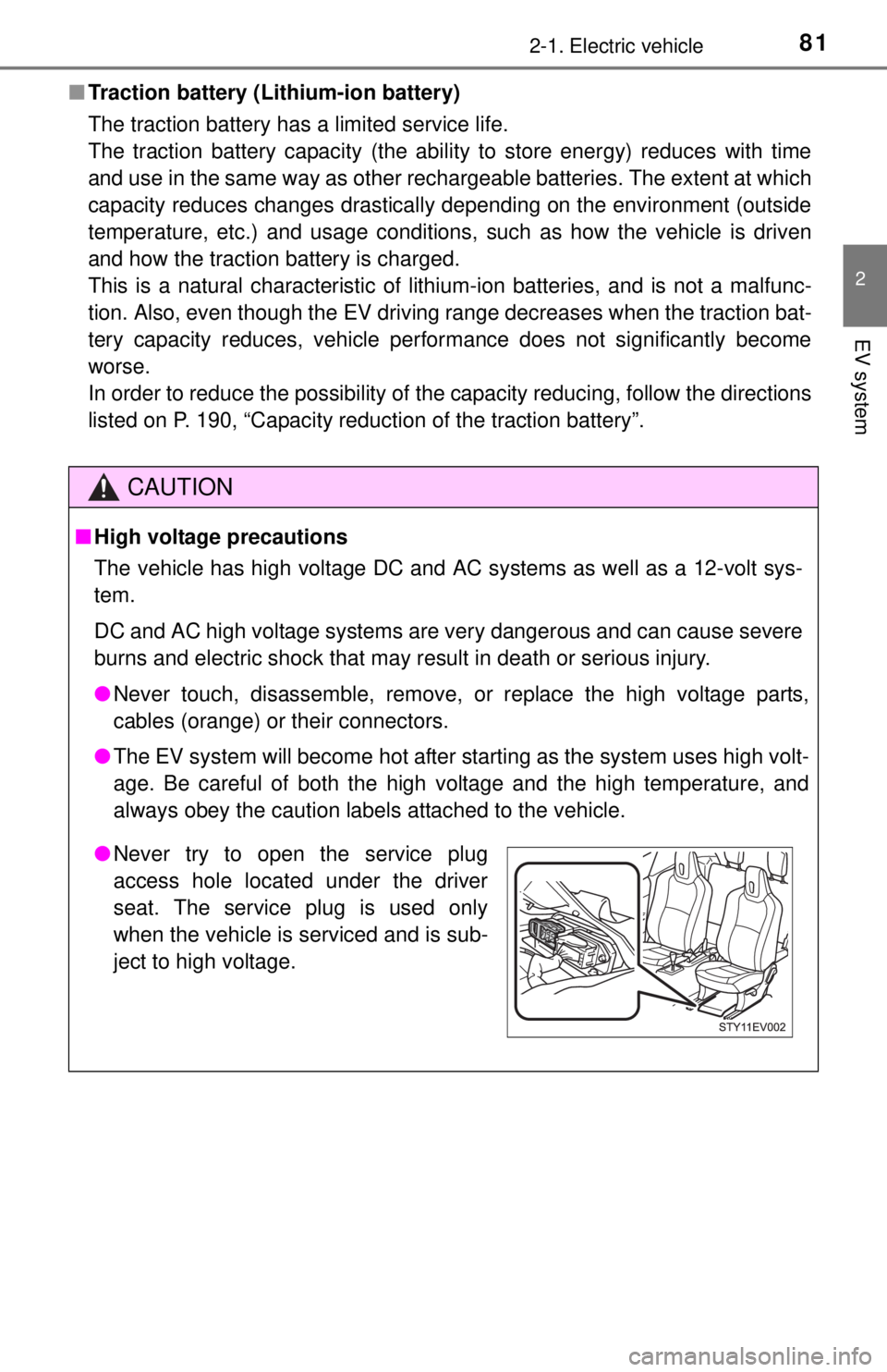
●Never try to open the service plug
access hole located under the driver
seat. The service plug is used only
when the vehicle is serviced and is sub-
ject to high voltage.
Page 91 of 444

912-2. Charging
2
EV system
Charge methods
The vehicle differs greatly from standard household electrical goods in
the following ways, and incorrect usage could cause fire and/or elec-
tric shock, possibly leading to death or serious injury.
● Large current flows for a long period of time.
● Charging can be conducted outdoors.
To charge properly, follow the procedure after reading the explanation
below. Charging is intended to be carried out by licensed drivers only
who properly understand the charging procedure. Charging should
not be carried out by children.
■Normal charging ( P. 181)
The traction battery can be charged from an AC outlet using the
vehicle’s charging cable or fr om charging equipment that is
installed at public charging stations or home.
■Quick charging (if equipped) ( P. 195)
The traction battery is charged in a short time with quick chargers
that are compliant with the CHA deMO (CHAdeMO is a trade name
of quick charging method) specifications.
The charging time varies depending on the battery temperature and the
type of a quick charger. However, the battery can only be charged from
when the SOC (State of Charge) warning light has come on up to 80%
in approximately 15 minutes.
In order to minimize decrease in the traction battery’s capacity, avoid
consecutive use of quick charging. Minimal use of quick charging is rec-
ommended.
The traction battery can be charged in the two ways: normal or
quick charging.
Charging methods
Page 115 of 444
1153. Instrument cluster
3
Instrument cluster
■Traction battery information
High or low temperatures of the traction battery, or traction battery’s remain-
ing charge being low may affect the motor performance.
Output performance: If the motor output performance has reduced, the maxi-
mum vehicle speed may be limited.
Regenerative performance: If the regenerative performance has reduced, the regenerative braking ability will be reduced.
Firmly depress the brake pedal.
■ Changes in possible driving range
●When the traction battery capacity has reduced, the possible driving range
will be calculated in accordance with such capacity. Therefore, the possible
driving ranges (highway, city) with the battery fully charged will be different
from those when the vehicle was new. ( P. 190)
● Estimated possible driving ranges are calculated based on power consump-
tion averages. Power-efficient driving manners ( P. 94) may increase the
estimated driving ranges.
● Air conditioning on or off affects possible driving ranges. Variation in possi-
ble driving ranges significantly varies depending on the previous energy
consumption of the air conditioning system, driving manners and weather.
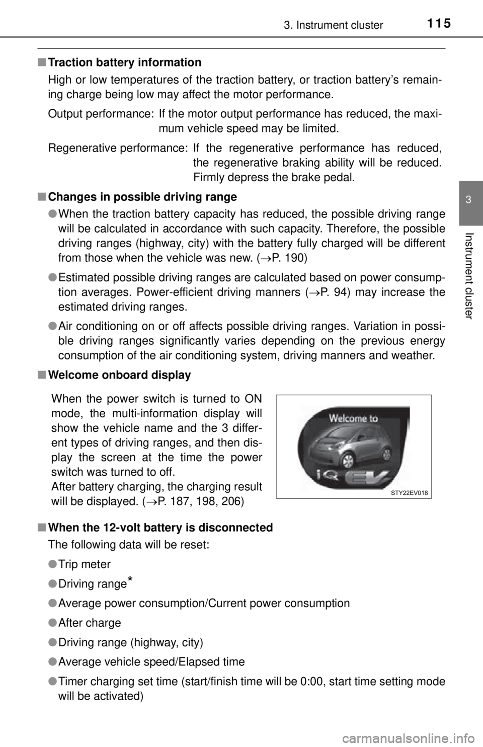
■ Welcome onboard display
■ When the 12-volt battery is disconnected
The following data will be reset:
●Trip meter
● Driving range
*
●Average power consumption/Current power consumption
● After charge
● Driving range (highway, city)
● Average vehicle speed/Elapsed time
● Timer charging set time (start/finish time will be 0:00, start time setting mode
will be activated)
When the power switch is turned to ON
mode, the multi-information display will
show the vehicle name and the 3 differ-
ent types of driving ranges, and then dis-
play the screen at the time the power
switch was turned to off.
After battery charging, the charging result
will be displayed. ( P. 187, 198, 206)
Page 190 of 444
1905-4. How to charge
■Charging time may increase
In the following situations, charging time may become longer than normal:
●In very hot or very cold temperatures.
● The vehicle is consuming a lot of electricity (the headlights or audio system
are on).
● There is a power outage during charging.
● Supply power is adjusted at charging stations.
● The supply voltage is unstable.
● The charge in the 12-volt battery is low, for example due to the vehicle being
left unused for a long period of time.
■ Capacity reduction of the traction battery
The charge of the traction battery will decline gradually when the traction bat-
tery is in use.
The rate at which it declines will differ in accordance with environmental con-
ditions and the way in which the vehicle is used. By observing the following
precautions, battery charge decline can be suppressed.
●Avoid charging during extremely hot weather.
● Avoid parking the vehicle in areas with a high temperature under direct sun-
light when the battery is fully charged.
● Do not charge the battery when the battery temperature is high. ( P. 109)
● Do not repeatedly perform charging when the battery is close to fully
charged.
● Use normal charging as much as possible.
● Charge battery only when low if not driving often to maximize battery life.
● If the vehicle will not be used for a long time, do not have the battery fully
charged. However, do not leave it completely discharged.
● Use the charging timer function as much as possible in order to fully charge
the traction battery immediately before starting off (the timer function cannot
be used during quick charging).
■ Handling the traction battery
P. 8 3
Page 200 of 444
2005-4. How to charge
■Capacity reduction of the traction battery
P. 190
■ Handling the traction battery
P. 8 3
■ When not using the vehicle for an extended period of time
P. 191
■ If the recharge inle t door cannot be opened
P. 191
CAUTION
■ When charging
Follow these points when charging. If you do not follow them, fire or electri-
cal shock may occur, possibly resulting in death or serious injury.
● Check that the charging cable and charging inlet are not damaged.
● Check that no foreign objects have been caught in charging connector or
inlet.
● Ensure that no water is in the charging connector or inlet.
● Do not touch the terminals of the charging connector or inlet, or allow a
short circuit to occur with foreign objects.
● Do not get the charging connector or inlet wet.
Do not wash the vehicle while the charging cable is connected to the vehi-
cle. ( P. 249)
● Do not touch the terminals of the charging connector or inlet with metallic
sharp tips (wires and needles).
● Do not use coiled up or tied up charging cables.
● Ensure that the charging cable is not bent or placed under heavy objects.
● If charging is interrupted, follow the quick charger’s instruction manual pro-
vided by the manufacturer.
Page 208 of 444
2085-4. How to charge
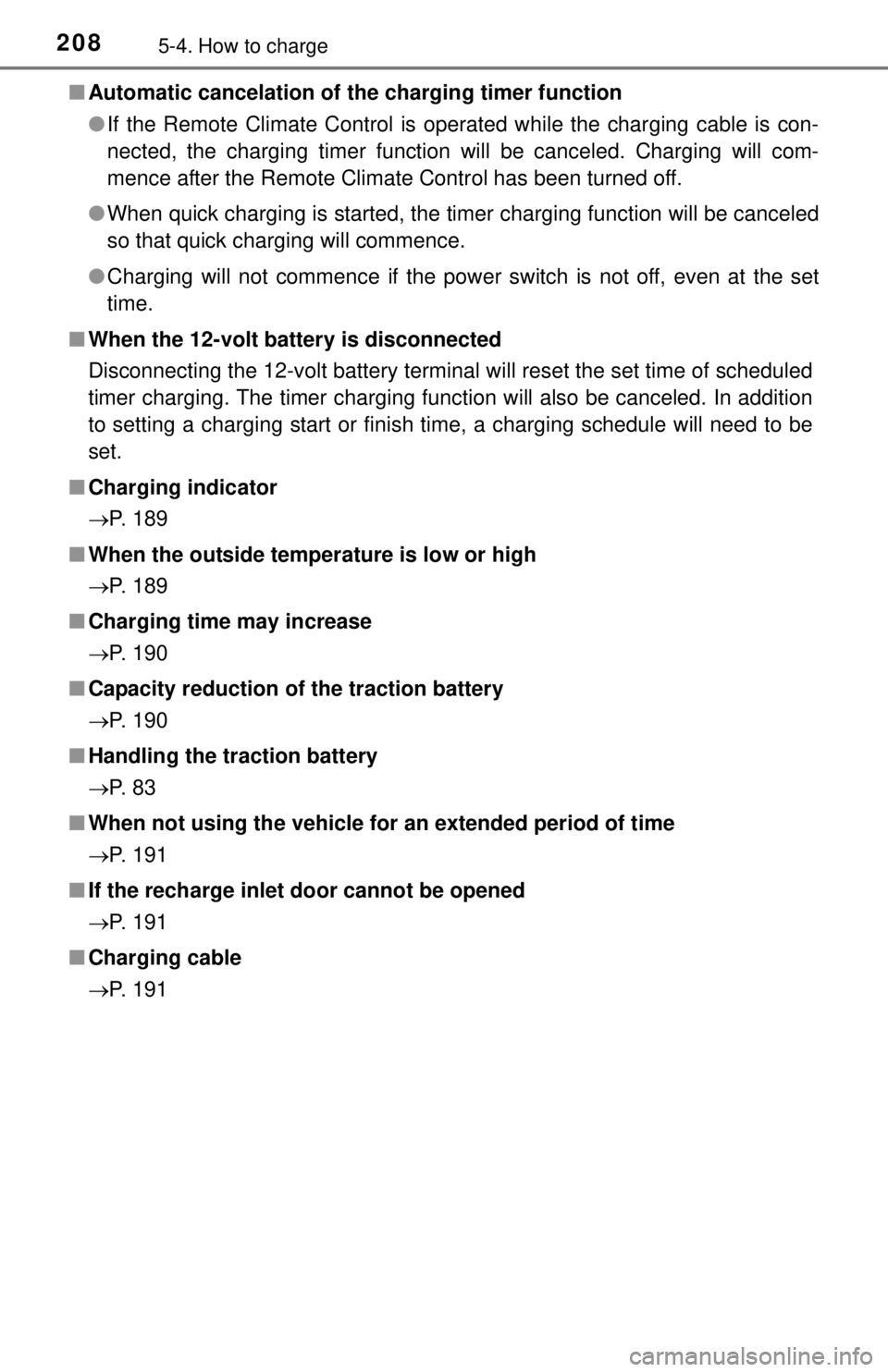
■Automatic cancelation of the charging timer function
●If the Remote Climate Control is operated while the charging cable is con-
nected, the charging timer function will be canceled. Charging will com-
mence after the Remote Climate Control has been turned off.
● When quick charging is started, the timer charging function will be canceled
so that quick charging will commence.
● Charging will not commence if the power switch is not off, even at the set
time.
■ When the 12-volt battery is disconnected
Disconnecting the 12-volt battery terminal will reset the set time of scheduled
timer charging. The timer charging func tion will also be canceled. In addition
to setting a charging start or finish time, a charging schedule will need to be
set.
■ Charging indicator
P. 189
■ When the outside temperature is low or high
P. 189
■ Charging time may increase
P. 190
■ Capacity reduction of the traction battery
P. 190
■ Handling the traction battery
P. 8 3
■ When not using the vehicle for an extended period of time
P. 191
■ If the recharge inle t door cannot be opened
P. 191
■ Charging cable
P. 191
Page 398 of 444

3989-1. Specifications
*: The capacity is a reference quantity. If replacement is necessary, contact your Scion dealer.
Electric motor (traction motor)
Ty p ePermanent magnet synchronous motor
Maximum output47 kW
Maximum torque120 ft·lbf (163 N·m, 16.6 kgf·m)
Traction battery
Ty p eLithium-ion battery
Voltage3.7 V/cell
Capacity21.5 Ah
Quantity150 cells
Overall voltage277.5 V
Cooling system
Capacity (Reference)*2.2 qt. (2.1 L, 1.8 Imp.qt.)
Coolant type
Use either of the following: • “Toyota Super Long Life Coolant”
• A similar high-quality ethylene glycol-basednon-silicate, non-amine, non-nitrite, and
non-borate coolant with long-life hybrid
organic acid technology
Do not use plain water alone.
Page 399 of 444

3999-1. Specifications
9
Vehicle specifications
*: The capacity is a reference quantity. If replacement is necessary, contact your Scion dealer.
*1: Minimum pedal clearance when depressed with a force of 66 lbf (300 N,30 kgf) while the EV system is operating.
*2: Parking brake lever travel when pulled up with a force of 44 lbf (200 N,20 kgf).
Electrical system
12-volt battery
Open voltage* at
68 F (20 C):12.6 12.8 V Fully charged
12.2
12.4 V Half charged
11 . 8
12.0 V Discharged
(
*: Voltage is checked 20 minutes after the EV
system and all lights are turned off.)
Charging rates5 A max.
Transmission
Fluid capacity*3.1 qt. (2.9 L, 2.6 Imp.qt.)
Fluid typeToyota Genuine ATF WS
NOTICE
■ Transmission fluid type
Using transmission fluid other than “Toyota Genuine ATF WS” may cause
deterioration in transmission performance, durability, and ultimately damage
the transmission of your vehicle.
Brakes
Pedal clearance*13.50 in. (89 mm) Min.
Pedal free play0.04 — 0.24 in. (1 — 6 mm)
Brake pad wear limit0.04 in. (1.0 mm)
Brake lining wear limit0.04 in. (1.0 mm)
Parking brake lever travel*25 — 8 clicks
Fluid typeFMVSS No. 116 DOT 3 or SAE J1703
Page 408 of 444
4089-1. Specifications
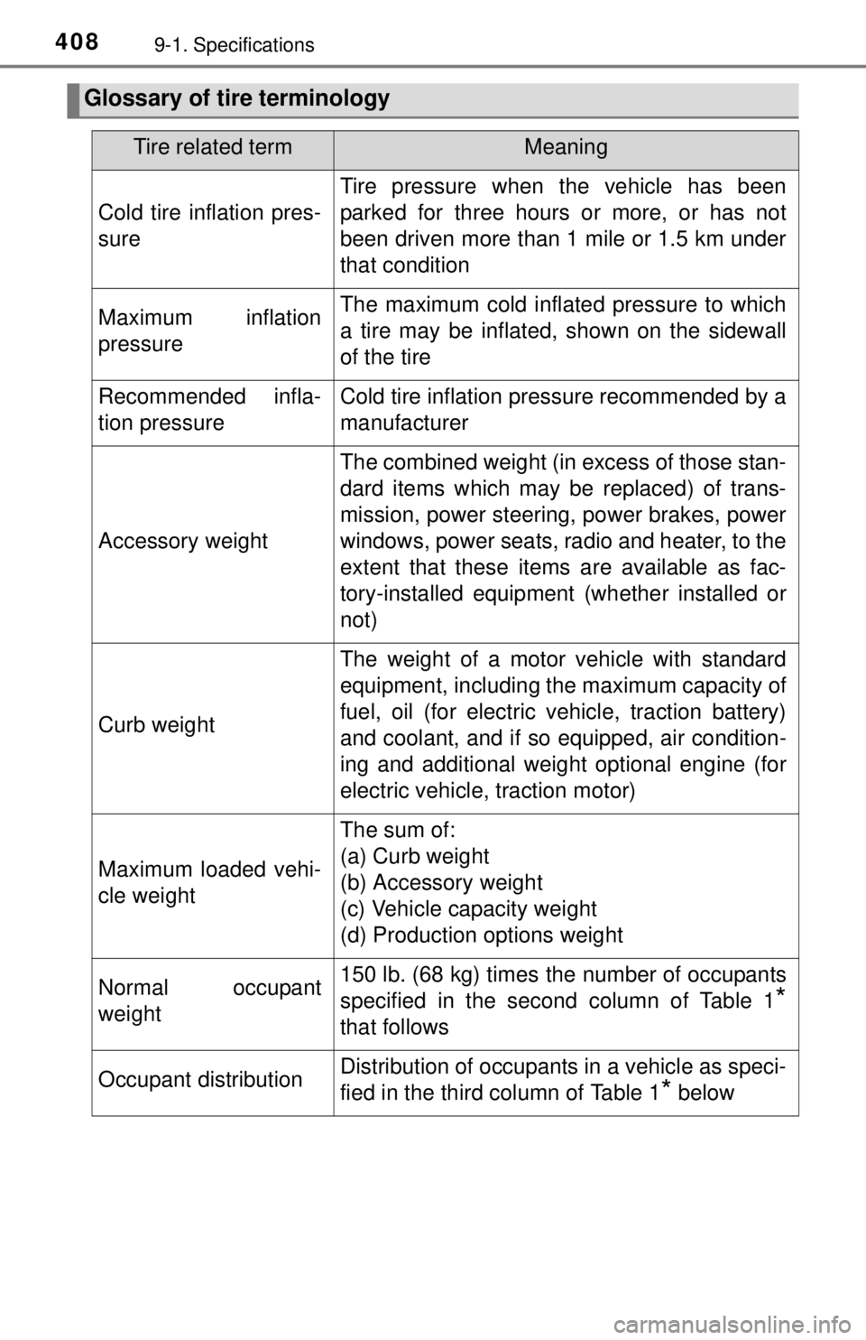
Glossary of tire terminology
Tire related termMeaning
Cold tire inflation pres-
sure
Tire pressure when the vehicle has been
parked for three hours or more, or has not
been driven more than 1 mile or 1.5 km under
that condition
Maximum inflation
pressureThe maximum cold inflated pressure to which
a tire may be inflated, shown on the sidewall
of the tire
Recommended infla-
tion pressureCold tire inflation pressure recommended by a
manufacturer
Accessory weight
The combined weight (in excess of those stan-
dard items which may be replaced) of trans-
mission, power steering, power brakes, power
windows, power seats, radio and heater, to the
extent that these item s are available as fac-
tory-installed equipment (whether installed or
not)
Curb weight
The weight of a motor vehicle with standard
equipment, including the maximum capacity of
fuel, oil (for electric vehicle, traction battery)
and coolant, and if so equipped, air condition-
ing and additional weight optional engine (for
electric vehicle, traction motor)
Maximum loaded vehi-
cle weight
The sum of:
(a) Curb weight
(b) Accessory weight
(c) Vehicle capacity weight
(d) Production options weight
Normal occupant
weight150 lb. (68 kg) times the number of occupants
specified in the second column of Table 1
*
that follows
Occupant distributionDistribution of occupants in a vehicle as speci-
fied in the third column of Table 1
* below
Page 409 of 444

4099-1. Specifications
9
Vehicle specifications
Production options
weight
The combined weight of installed regular pro-
duction options weighing over 5 lb. (2.3 kg) in
excess of the standard items which they
replace, not previously considered in curb
weight or accessory weight, including heavy
duty brakes, ride levelers, roof rack, heavy
duty 12-volt battery, and special trim
Rim
A metal support for a tire or a tire and tube
assembly upon which the tire beads are
seated
Rim diameter
(Wheel diameter)Nominal diameter of the bead seat
Rim size designationRim diameter and width
Rim type designationThe industry manufacturer’s designation for a
rim by style or code
Rim widthNominal distance between rim flanges
Vehicle capacity
weight (Total load
capacity)The rated cargo and luggage load plus 150 lb.
(68 kg) times the vehicle’s designated seating
capacity
Vehicle maximum load
on the tire
The load on an individual tire that is deter-
mined by distributing to each axle its share of
the maximum loaded vehicle weight, and
dividing by two
Vehicle normal load on
the tire
The load on an individual tire that is deter-
mined by distributing to each axle its share of
curb weight, accessory weight, and normal
occupant weight (distributed in accordance
with Table 1
* below), and dividing by two
Weather sideThe surface area of the rim not covered by the
inflated tire
Bead
The part of the tire that is made of steel wires,
wrapped or reinforced by ply cords and that is
shaped to fit the rim
Bead separationA breakdown of the bond between compo-
nents in the bead
Tire related termMeaning