ECU TOYOTA MIRAI 2022 Repair Manual
[x] Cancel search | Manufacturer: TOYOTA, Model Year: 2022, Model line: MIRAI, Model: TOYOTA MIRAI 2022Pages: 556, PDF Size: 17.34 MB
Page 464 of 556
4648-2. Steps to take in an emergency
Owners Manual_USA_M62084_en
WARNING
■Do not drive the vehicle with
a flat tire
Do not continue driving with a flat
tire.
Driving even a short distance with
a flat tire can damage the tire and
the wheel beyond repair.
Driving with a flat tire may cause a
circumferential groove on the side
wall. In such a case, the tire may
explode when using a repair kit.
■When fixing the flat tire
●Stop your vehicle in a safe and
flat area.
●Do not touch the wheels or the
area around the brakes immedi-
ately after the vehicle has been
driven.
After the vehicle has been
driven, the wheels and the area
around the brakes may be
extremely hot. Touching these
areas with hands , feet or other
body parts may result in burns.
●Connect the valve and hose
securely with the tire installed
on the vehicle. If the hose is not
properly connected to the valve,
air leakage may occur as seal-
ant may be sprayed out.
●If the hose comes off the valve
while inflating the tire, there is a
risk that the hose will move
abruptly due to air pressure.
●After inflation of the tire has
completed, the sealant may
splatter when the hose is dis-
connected or some air is let out
of the tire.
●Follow the operation procedure
to repair the tire. If the proce-
dures not followed, the sealant
may spray out.
●Keep back from the tire while it
is being repaired, as there is a
chance of it bursting while the
repair operation is being per-
formed. If you notice any cracks
or deformation of the tire, turn
off the compressor switch and
stop the repair operation imme-
diately.
●The repair kit may overheat if
operated for a long period of
time. Do not operate the repair
kit continuously for more than
40 minutes.
●Parts of the re pair kit become
hot during operation. Be careful
handling the repair kit during
and after operation. Do not
touch the metal part connecting
the bottle and the compressor. It
will be extremely hot.
●Do not attach the vehicle speed
warning sticker to an area other
than the one indicated. If the
sticker is attached to an area
where an SRS airbag is located,
such as the pad of the steering
wheel, it may prevent the SRS
airbag from operating properly.
■Driving to spread the liquid
sealant evenly
Observe the following precautions
to reduce the risk of accidents.
Failing to do so may result in a
loss of vehicle control and cause
death or serious injury.
●Drive the vehicle carefully at a
low speed. Be especially careful
when turning and cornering.
●If the vehicle does not drive
straight or you feel a pull
through the steering wheel, stop
the vehicle and check the fol-
lowing.
• Tire condition. The tire may have separated from the wheel.
Page 473 of 556
4738-2. Steps to take in an emergency
Owners Manual_USA_M62084_en
8
When trouble arises
■Starting the fuel cell system
when the 12-volt battery is dis-
charged
The fuel cell system cannot be
started by push-starting.
■To prevent 12-volt battery dis-
charge
●Turn off the headlights and the
audio system while the fuel cell
system is off.
●Turn off any unnecessary electri-
cal components when the vehicle
is running at a low speed for an
extended period, such as in heavy
traffic.
■When the 12-volt battery is
removed or discharged
●Information stor ed in the ECU is
cleared. When the 12-volt battery
is depleted, have the vehicle
inspected at you r Toyota dealer.
●Some systems may require initial-
ization. ( P.510)
●If the 12-volt battery discharges, it
may not be possible to shift the
shift position to other positions.
In this case, the vehicle cannot be
towed without lifting both rear
wheels because the rear wheels will
be locked.
■When removing the 12-volt bat-
tery terminals
When the 12-volt battery terminals
are removed, the information stored
in the ECU is cleared. Before
removing the 12-volt battery termi-
nals, contact your Toyota dealer.
■Charging the 1 2-volt battery
The electricity stor ed in the 12-volt
battery will discharge gradually even
when the vehicle is not in use, due
to natural discharge and the drain-
ing effects of certain electrical appli-
ances. If the vehicle is left for a long
time, the 12-volt battery may dis-
charge, and the fuel cell system
may be unable to s tart. (The 12-volt battery recharges automatically
while the fuel cell
system is operat-
ing.)
■When recharging or replacing
the 12-volt battery
●In some cases, it may not be pos-
sible to unlock the doors using the
smart key system when the 12-
volt battery is discharged. Use the
wireless remote c ontrol or the
mechanical key to lock or unlock
the doors.
●The fuel cell system may not start
on the first attempt after the 12-
volt battery has recharged but will
start normally after the second
attempt. This is not a malfunction.
●The power switch mode is memo-
rized by the vehicle. When the 12-
volt battery is reconnected, the
system will return to the mode it
was in before the 12-volt battery
was discharged. Before discon-
necting the 12-volt battery, turn
the power switch off.
If you are unsure what mode the
power switch was in before the
12-volt battery discharged, be
especially careful when recon-
necting the 12-volt battery.
●When the 12-volt battery is recon-
nected, start the fuel cell system,
depress the brake pedal, and con-
firm that it is possible to shift into
each shift position.
●If the battery is removed or the ter-
minals disconnected without oper-
ating the water release function
during cold weather, the vehicle
may not start due to the fuel cell
system being frozen. To prevent
this, operate th e water release
function before removing the bat-
tery or disconnecting the termi-
nals. ( P.189)
■When replacing t he 12-volt bat-
tery
●Use a Central De gassing type 12-
volt battery (European Regula-
tions).
Page 474 of 556
4748-2. Steps to take in an emergency
Owners Manual_USA_M62084_en
●Use a 12-volt battery with the
same case size as the previous
12-volt battery and an equivalent
20 hour rate capacity (20HR) or
greater.
• If the sizes differ, the 12-volt bat-
tery cannot be properly secured.
• If the 20 hour rate capacity is low,
even if the time period where the
vehicle is not used is a short time,
the 12-volt battery may discharge
and the fuel cell system may not
be able to start.
●Use a 12-volt battery with a han-
dle. If a 12-volt b attery without a
handle is used, removal is more
difficult.
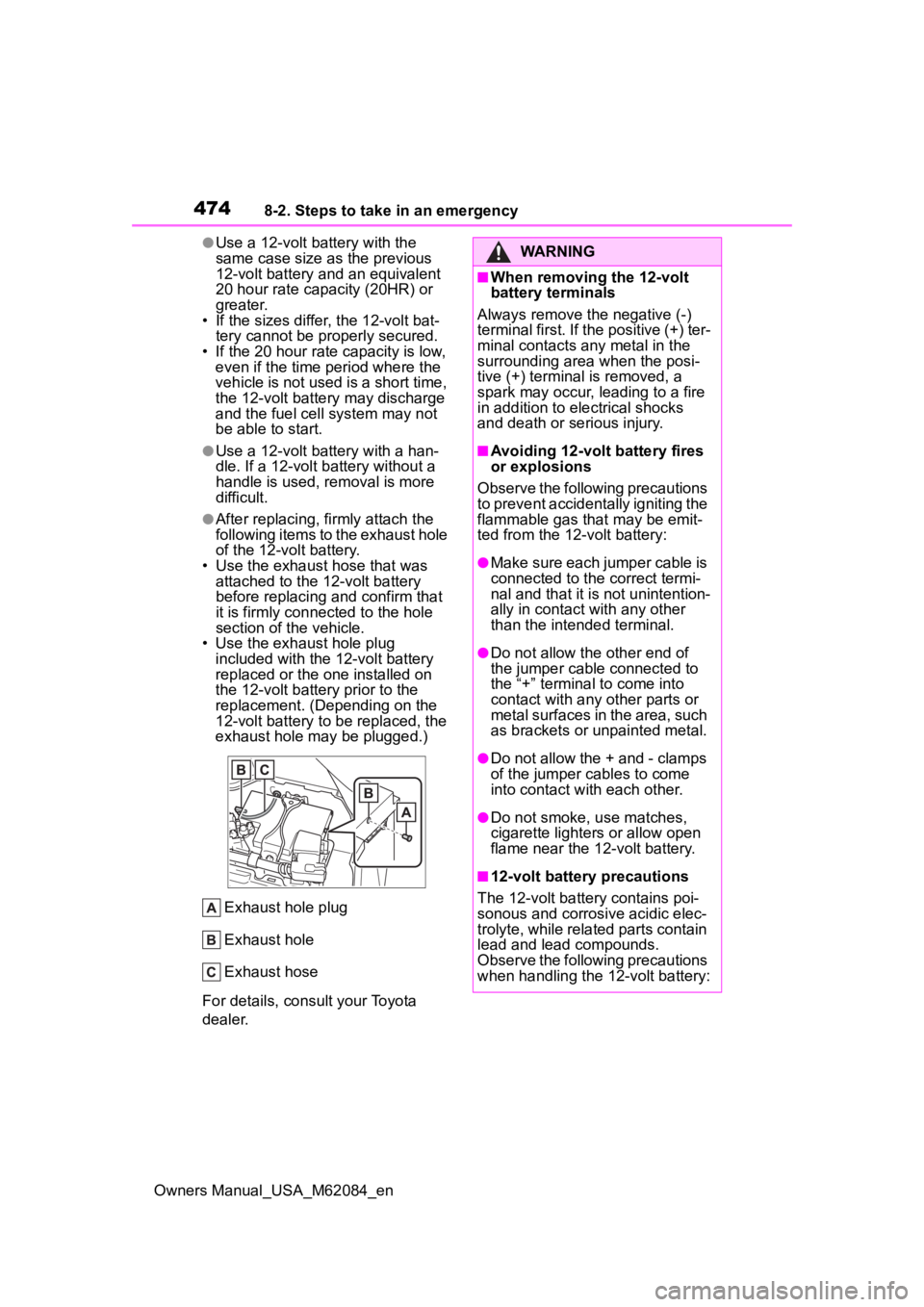
●After replacing, firmly attach the
following items to the exhaust hole
of the 12-volt battery.
• Use the exhaust hose that was attached to the 12-volt battery
before replacing an d confirm that
it is firmly connected to the hole
section of t he vehicle.
• Use the exhaust hole plug included with the 12-volt battery
replaced or the one installed on
the 12-volt battery prior to the
replacement. (Depending on the
12-volt battery to be replaced, the
exhaust hole may be plugged.)
Exhaust hole plug
Exhaust hole
Exhaust hose
For details, consult your Toyota
dealer.
WARNING
■When removing the 12-volt
battery terminals
Always remove the negative (-)
terminal first. If the positive (+) ter-
minal contacts any metal in the
surrounding area when the posi-
tive (+) terminal is removed, a
spark may occur, leading to a fire
in addition to ele ctrical shocks
and death or serious injury.
■Avoiding 12-volt battery fires
or explosions
Observe the following precautions
to prevent accidentally igniting the
flammable gas that may be emit-
ted from the 12-volt battery:
●Make sure each jumper cable is
connected to the correct termi-
nal and that it is not unintention-
ally in contact with any other
than the intended terminal.
●Do not allow the other end of
the jumper cable connected to
the “+” terminal to come into
contact with any other parts or
metal surfaces in the area, such
as brackets or unpainted metal.
●Do not allow the + and - clamps
of the jumper cables to come
into contact with each other.
●Do not smoke, use matches,
cigarette lighter s or allow open
flame near the 1 2-volt battery.
■12-volt battery precautions
The 12-volt battery contains poi-
sonous and corrosive acidic elec-
trolyte, while related parts contain
lead and lead compounds.
Observe the following precautions
when handling the 12-volt battery:
Page 475 of 556

4758-2. Steps to take in an emergency
Owners Manual_USA_M62084_en
8
When trouble arises
WARNING
●When working with the 12-volt
battery, always wear safety
glasses and take care not to
allow any battery fluids (acid) to
come into contact with skin,
clothing or the vehicle body.
●Do not lean over the 12-volt bat-
tery.
●In the event that battery fluid
comes into contact with the skin
or eyes, immediately wash the
affected area with water and
seek medical attention. Place a
wet sponge or cloth over the
affected area until medical
attention can be received.
●Always wash your hands after
handling the 12-volt battery sup-
port, terminals, and other bat-
tery-related parts.
●Do not allow child ren near the
12-volt battery.
■After recharging the 12-volt
battery
Have the 12-volt battery
inspected at your Toyota dealer
as soon as possible.
If the 12-volt battery is deteriorat-
ing, continued use may cause the
12-volt battery to emit a malodor-
ous gas, which may be detrimen-
tal to the health of passengers.
■When replacing the 12-volt
battery
●When the vent plug and indica-
tor are close to the hold down
clamp, the battery fluid (sulfuric
acid) may leak.
●For information regarding 12-
volt battery rep lacement, con-
tact your Toyota dealer.
●After replacing, s ecurely attach
the exhaust hose and exhaust
hole plug to the exhaust hole of
the replaced 12-volt battery. If
not properly installed, gases
(hydrogen) may leak into the
vehicle interior, and there is the
possible danger of the gas ignit-
ing and exploding.
NOTICE
■When handling jumper cables
When connecting the jumper
cables, ensure that they do not
become entangled in the cooling
fan.
■To prevent damaging the
vehicle
The exclusive jump starting termi-
nal is to be used when charging
the 12-volt battery from another
vehicle in an emergency. It cannot
be used to jump start another
vehicle.
Page 497 of 556

4979-1. Specifications
Owners Manual_USA_M62084_en
9
Vehicle specifications
*: Table 1 -Occupant loading and di stribution for vehicle normal load for var-
ious designated seating capacities
Tread ribA tread section running circumferentially
around a tire
Tread separationPulling away of the tread from the tire car-
cass
Treadwear indicators (TWI)
The projections within the principal
grooves designed to give a visual indica-
tion of the degrees o f wear of the tread
Wheel-holding fixtureThe fixture used to hold the wheel and tire
assembly securely during testing
Tire related termMeaning
Designated seating
capacity, Number of occupantsVehicle normal load,
Number of occupantsOccupant distribution in a normally loaded vehi- cle
2 through 422 in front
5 through 1032 in front, 1 in second
seat
11 through 155
2 in front, 1 in second
seat, 1 in third seat, 1 in fourth seat
16 through 207
2 in front, 2 in second
seat, 2 in third seat, 1 in fourth seat
Page 502 of 556
5029-2. Customization
Owners Manual_USA_M62084_en
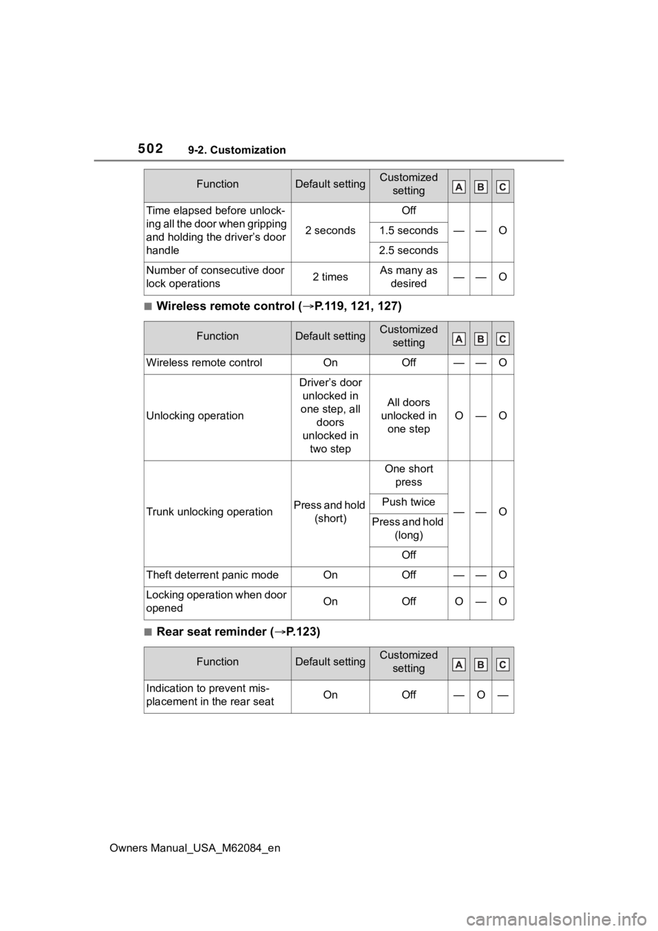
■Wireless remote control (P.119, 121, 127)
■Rear seat reminder (P.123)
Time elapsed before unlock-
ing all the door when gripping
and holding the driver’s door
handle
2 seconds
Off
——O1.5 seconds
2.5 seconds
Number of consecutive door
lock operations2 timesAs many as
desired——O
FunctionDefault settingCustomized setting
Wireless remote controlOnOff——O
Unlocking operation
Driver’s door unlocked in
one step, all doors
unlocked in two step
All doors
unlocked in one step
O—O
Trunk unlocking operationPress and hold (short)
One short press
——OPush twice
Press and hold (long)
Off
Theft deterrent panic modeOnOff——O
Locking operation when door
openedOnOffO—O
FunctionDefault settingCustomized setting
Indication to prevent mis-
placement in the rear seatOnOff—O—
FunctionDefault settingCustomized setting
Page 512 of 556

51210-1. For owners
Owners Manual_USA_M62084_en
10-1.For owners
Repor ting safety
defects for U.S. own-
ers
If you believe that your vehicle
has a defect which could
cause a crash or could cause
injury or death, you should
immediately inform the
National Highway Traffic
Safety Administration
(NHTSA) in addition to notify-
ing Toyota Motor Sales,
U.S.A., Inc. (Toll-free: 1-800-
331-4331).
If NHTSA receives similar
complaints, it may open an
investigation, and if it finds
that a safety defect exists in a
group of vehicles, it may order
a recall and remedy cam-
paign. However, NHTSA can-
not become involved in
individual problems between
you, your dealer, or Toyota
Motor Sales, U.S.A., Inc.
To contact NHTSA, you may
call the Vehicle Safety Hotline
toll-free at 1-888-327-4236
(TTY: 1-800-424-9153); go to
http://www.safercar.gov; or
write to: Administrator,
NHTSA, 1200 New Jersey
Ave. SE., Washington, DC
20590. You can also obtain
other information about motor
vehicle safety from
http://www.safercar.gov .
Reporting safety
defects for Canadian
owners
Canadian customers who
wish to report a safety-related
defect to Transport Canada,
Defects Investigations and
Recalls, may telephone the
toll-free hotline 1-800-333-
0510, mail Transport Canada -
ASFAD, 330 Sparks Street,
Ottawa, ON, K1A 0N5, or
complete the online form at
https://www.tc.gc.ca/recalls .
Les clients canadiens
désireux de rendre compte
d’un défaut lié à la sécurité
auprès de Transport Canada,
Enquêtes sur les défauts et
rappels, peuvent appeler gra-
tuitement l’assistance télépho-
nique au 1-800-333-0510,
écrire un courriel à Transports
Canada - ASFAD, 330 Sparks
Street, Ottawa, ON, K1A 0N5,
ou remplir la déclaration en
ligne à l’adresse
https://www.tc.gc.ca/rappels .
Page 513 of 556

51310-1. For owners
Owners Manual_USA_M62084_en
10
For owners
Tirez sur la ceinture épaulière
jusqu’à ce qu’elle recouvre
entièrement l’épaule; elle ne
doit cependant pas toucher le
cou ni glisser de l’épaule.
Placez la ceinture abdominale
le plus bas possible sur les
hanches.
Réglez la position du dossier.
Tenez-vous assis bien au
fond du siège, le dos droit.
Ne vrillez pas la ceinture de
sécurité.
■Manipulation des ceintures
de sécurité
Avec un chiffon ou une éponge,
nettoyez à l’aide d’un savon
doux et de l’eau tiède. Vérifiez
aussi les ceintures régulière-
ment pour vous assurer qu’elles
ne présentent pas d’usure
excessive, d’effilochage ou de
coupures.
Seat belt instructions
for Canadian owners
(in French)
The following is a French
explanation of seat belt
instructions extracted from
the seat belt section in this
manual.
See the seat belt section for
more detailed seat belt
instructions in English.
Utilisation adéquate des
ceintures de sécurité
Entretien et nettoyage
AVERTISSEMENT
■Dommages et usure de la
ceinture de sécurité
Vérifiez périodiquement le sys-
tème de ceintures de sécurité.
Vérifiez qu’il n’y a pas de cou-
pures, d’effilochures ni de pièces
desserrées. N’utilisez pas une
ceinture de sécurité endommagée
avant qu’elle ne soit remplacée.
Les ceintures de sécurité endom-
magées ne peuvent pas protéger
les occupants contre les bless-
ures graves, voire mortelles.
Page 515 of 556

51510-1. For owners
Owners Manual_USA_M62084_en
10
For owners
Coussins gonflables SRS latéraux et en rideau Coussins gonflables SRS latéraux avant
Peuvent aider à protéger le torse des occupants des sièges avan t
Coussins gonflables SRS en rideau
• Peuvent aider à protéger principalement la tête des occupants des sièges
latéraux
• Peuvent aider à empêcher les occu pants d’être éjectés du véhicule en
cas de tonneaux
■Composants du système de coussins gonflables SRS
Capteurs d’impact avant
Coussins gonflables de protection des genoux
Coussin gonflable du passager avant
Coussins gonflables en rideau
Capteurs d’impact latéral (portière avant)
Dispositifs de tension des ceintures de sécurité
Coussins gonflables latéraux
Lampe témoin SRS
Coussin gonflable du conducteur
Page 516 of 556

51610-1. For owners
Owners Manual_USA_M62084_en
Capteurs d’impact latéral (arrière)
Capteurs d’impact latéral (avant)
Capteur de position du siège du conducteur
Contacteur de boucle de ceinture de sécurité du conducteur
Module de capteur de coussin gonflable
Système de classification de l’occupant du siège du passager
avant (ECU et capteurs)
Voyants “AIRBAG ON” et “AIRBAG OFF”
Votre véhicule est doté de COUSSINS GONFLABLES ÉVOLUÉS
dont la conception s’appuie sur les normes de sécurité des véhi cules
à moteur américains (FMVSS208). Le module de capteur de coussin
gonflable (ECU) contrôle le déploiement des coussins gonflables en
fonction des informations obtenues des capteurs et d’autres élé-
ments affichés dans le diagramme des composants du système ci-
dessus. Ces informations comprennent des données relatives à la
gravité de l’accident et aux occupants. Au moment du déploiement
des coussins gonflables, une réaction chimique se produit dans les
gonfleurs de coussin gonflable et les coussins gonflables se remplis-
sent rapidement d’un gaz non toxique pour aider à limiter le mo uve-
ment des occupants.
AVERTISSEMENT
■Précautions relatives aux
coussins gonflables SRS
Observez les pré cautions suiva-
ntes en ce qui concerne les cous-
sins gonflables SRS.
Négliger de le faire pourrait occa-
sionner des blessures graves,
voire mortelles.
●Le conducteur et tous les pas-
sagers du véhicule doivent por-
ter leur ceinture de sécurité de
la manière appropriée.
Les coussins gonflables SRS
sont des disposit ifs supplémen-
taires qui doivent être utilisés
avec les ceintures de sécurité.