open hood TOYOTA MIRAI 2023 User Guide
[x] Cancel search | Manufacturer: TOYOTA, Model Year: 2023, Model line: MIRAI, Model: TOYOTA MIRAI 2023Pages: 572, PDF Size: 17.71 MB
Page 485 of 572
4858-2. Steps to take in an emergency
Owners Manual_USA_M62064_en
8
When trouble arises
If you have a set of jumper (or
booster) cables and a second
vehicle with a 12-volt battery,
you can jump start your vehicle
by following the steps below.
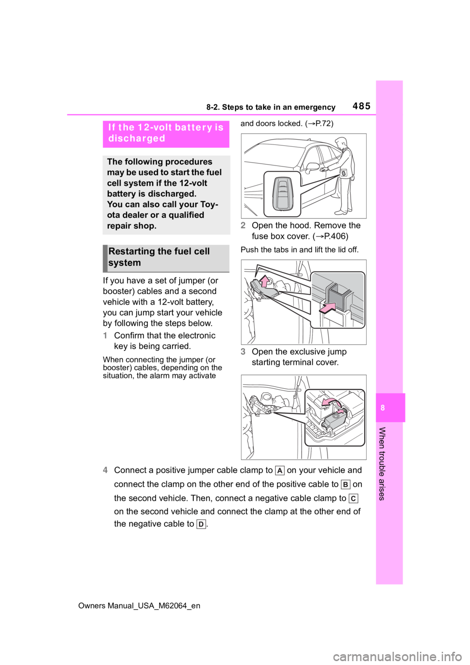
1 Confirm that the electronic
key is being carried.
When connecting the jumper (or
booster) cables, depending on the
situation, the ala rm may activate and doors locked. (
P. 7 2 )
2 Open the hood. Remove the
fuse box cover. ( P.406)
Push the tabs in and lift the lid off.
3 Open the exclusive jump
starting terminal cover.
4 Connect a positive jumper cabl e clamp to on your vehicle and
connect the clamp on the other end of the positive cable to on
the second vehicle. Then, connect a negative cable clamp to
on the second vehicle and connect the clamp at the other end of
the negative cable to .
If the 12-volt batter y is
discharged
The following procedures
may be used to start the fuel
cell system if the 12-volt
battery is discharged.
You can also call your Toy-
ota dealer or a qualified
repair shop.
Restarting the fuel cell
system
Page 493 of 572
4938-2. Steps to take in an emergency
Owners Manual_USA_M62064_en
8
When trouble arises
able.
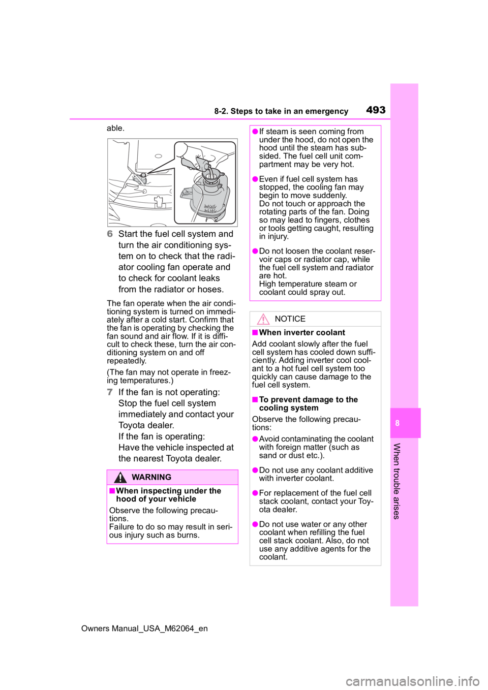
6 Start the fuel cell system and
turn the air conditioning sys-
tem on to check that the radi-
ator cooling fan operate and
to check for coolant leaks
from the radiator or hoses.
The fan operate when the air condi-
tioning system is turned on immedi-
ately after a cold s tart. Confirm that
the fan is operating by checking the
fan sound and air flow. If it is diffi-
cult to check these, turn the air con-
ditioning system on and off
repeatedly.
(The fan may not o perate in freez-
ing temperatures.)
7 If the fan is not operating:
Stop the fuel cell system
immediately and contact your
Toyota dealer.
If the fan is operating:
Have the vehicle inspected at
the nearest Toyota dealer.
WARNING
■When inspecting under the
hood of your vehicle
Observe the following precau-
tions.
Failure to do so may result in seri-
ous injury such as burns.
●If steam is seen coming from
under the hood, do not open the
hood until the steam has sub-
sided. The fuel cell unit com-
partment may be very hot.
●Even if fuel cell system has
stopped, the cooling fan may
begin to move suddenly.
Do not touch or approach the
rotating parts of the fan. Doing
so may lead to fingers, clothes
or tools getting caught, resulting
in injury.
●Do not loosen the coolant reser-
voir caps or radia tor cap, while
the fuel cell system and radiator
are hot.
High temperature steam or
coolant could spray out.
NOTICE
■When inverter coolant
Add coolant slowly after the fuel
cell system has cooled down suffi-
ciently. Adding inverter cool cool-
ant to a hot fuel cell system too
quickly can cause damage to the
fuel cell system.
■To prevent damage to the
cooling system
Observe the following precau-
tions:
●Avoid contaminating the coolant
with foreign matter (such as
sand or dust etc.).
●Do not use any coolant additive
with inverter coolant.
●For replacement of the fuel cell
stack coolant, contact your Toy-
ota dealer.
●Do not use water or any other
coolant when refilling the fuel
cell stack coolant. Also, do not
use any additive agents for the
coolant.
Page 548 of 572

548Alphabetical Index
Owners Manual_USA_M62064_en
Fuel cell unit compartment cover ............................................... 409
Fuel consumption Average fuel economy ......... 107
Current fuel economy ........... 107
Fuel door ........................... ...... 210
Refueling .............................. 210
When the fuel door cannot be opened ............................... 482
Fuel economy ......... ................ 107
Fuel gauge ........................ 99, 102
Fuses ....................................... 438
G
Garage door opener ............... 382
Gauges .............................. 99, 102
Glove box ................................ 358
Glove box light ....................... 359
H
Head restraints ....................... 145
Head-up display ..................... 114 Driving information display area........................................... 114
Driving support system display area .................................... 117
Fuel cell System Indicator .... 118
HUD (Head-up display) switch ........................................... 116
Navigation system-linked display ........................................... 114
Outside temperature ............ 114
Pop-up display ..................... 117
Settings ................................ 116
Headlights Automatic High Beam .......... 200
Light switch .......................... 198
Replacing light bulbs ............ 443
Heated steering wheel ........... 351 Heaters
Automatic air conditioning sys-tem .............................333, 340
Heated steering wheel..........351
Outside rear view mirrors ...335, 342
Seat heaters ....... ..................351
High mounted stoplight Replacing light bulbs ............443
High-voltage components .......81
Hill-start assist control...........322
Hood ........................................406 Open.....................................406
Pop Up Hood ..........................43
Hooks Coat hooks ...........................372
Retaining hooks (floor mat) ....26
Horn .........................................148
HUD (Head-up display) switch ............................................... 116
Hydrogen detecto rs..................84
Hydrogen tanks ............76, 81, 83 Capacity ...............................497
Location ............................76, 81
Hydrogen-related components81
I
Identification Vehicle ..................................496
Ignition switch (power switch) ...............................................180
Immobilizer system ..................70
Indicators ..................................97
Initialization Electronic sunshade .............363
Items to initialize ...................526
Power windows ....................162
Tire pressure w arning system
...........................................420
Inside door handle lights .......355
Inside rear view m irror ...........149
Page 550 of 572

550Alphabetical Index
Owners Manual_USA_M62064_en
M
Maintenance Do-it-yourself maintenance .. 404
General maintenance ........... 401
Maintenance data................. 496
Maintenance requirements... 400
Menu icons ............................. 107
Meter Clock .............................. 99, 102
Driving range .................. 99, 102
Indicators................................ 97
Instrument panel light control................................... 100, 104
Meter control switches ......... 106
Meters ............................ 99, 102
Multi-information display ...... 105
Settings ................................ 111
Warning lights................. 95, 454
Warning message ................ 464
Meter control switches .......... 106
Mirrors Digital Rear-view Mirror........ 150
Inside rear view mirror.......... 149
Outside rear view mirror defog-gers ............................ 335, 342
Outside rear view mirrors ..... 160
Vanity mirrors ....................... 380
Multi-information display....... 105 Air purification screen........... 119
Audio system-linked display . 111
Changing the display............ 106
Consumption screen ............ 119
Driving information display ... 107
Driving support system informa-tion display ......................... 110
Dynamic radar cruise control with full-speed range .......... 244
ECO Accelerator Guidance .. 108
Eco score ............................. 108
Energy monitor ..................... 119
Fuel cell System Indicator .... 108 Fuel economy .......................107
LTA (Lane Tracing Assist) .....236
Menu icons ...........................107
Meter control switches..........106
Navigation system-linked display
........................................... 110
Settings ................................ 111
Suggestion function .............. 112
Tire inflation pressure ........... 111
Tire pressure ...... ..................418
Vehicle information display ... 111
Warning message.................464
N
Navigation system-linked display ....................................... 110, 114
O
Odometer.........................100, 104
Odometer and trip meter display Display change button ..100, 104
Display items ................100, 104
Opener Fuel door ..............................210
Hood .....................................406
Trunk ....................................133
Outer foot lights......................355
Outside rear view mirrors Adjustment ...........................160
BSM (Blind Spot M onitor) .....256
Folding..................................161
Mirror position me mory.........142
Outside rear view mirror defog- gers ............................335, 342
RCTA (Rear Cross Traffic Alert) ...........................................272
Outside temperature ........99, 102
Overheating.............................490
Page 572 of 572

572
Owners Manual_USA_M62064_en
HYDROGEN STATION INFORMATION
Auxiliary catch lever (P.406)
Trunk opener ( P.133)
Fuel door ( P.212)
Fuel door opener ( P.212)
Hood lock release lever ( P.406)
Tire inflation pressure ( P.501)
Hydrogen tanks’
fuel capacityP.497
Fuel typeCompressed hydrogen gasP.497
Cold tire inflation
pressureP.501