TOYOTA PRIUS 2001 Service Repair Manual
Manufacturer: TOYOTA, Model Year: 2001, Model line: PRIUS, Model: TOYOTA PRIUS 2001Pages: 1943, PDF Size: 18.26 MB
Page 131 of 1943
2001 PRIUS (EWD414U)
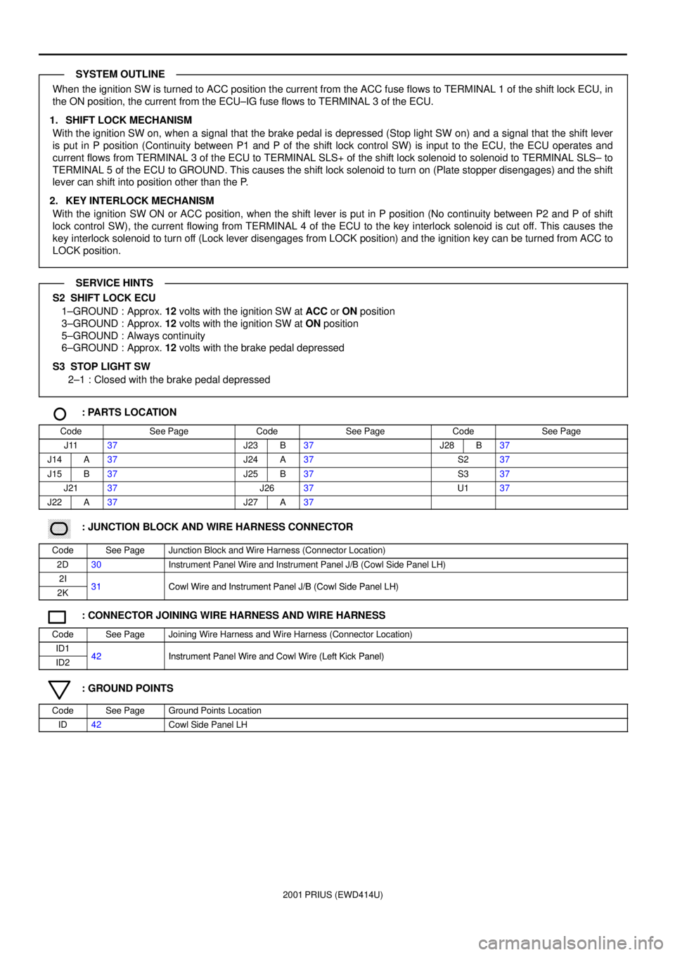
When the ignition SW is turned to ACC position the current from the ACC fuse flows to TERMINAL 1 of the shift lock ECU, in
the ON position, the current from the ECU±IG fuse flows to TERMINAL 3 of the ECU.
1. SHIFT LOCK MECHANISM
With the ignition SW on, when a signal that the brake pedal is depressed (Stop light SW on) and a signal that the shift lever
is put in P position (Continuity between P1 and P of the shift lock control SW) is input to the ECU, the ECU operates and
current flows from TERMINAL 3 of the ECU to TERMINAL SLS+ of the shift lock solenoid to solenoid to TERMINAL SLS± to
TERMINAL 5 of the ECU to GROUND. This causes the shift lock solenoid to turn on (Plate stopper disengages) and the shift
lever can shift into position other than the P.
2. KEY INTERLOCK MECHANISM
With the ignition SW ON or ACC position, when the shift lever is put in P position (No continuity between P2 and P of shift
lock control SW), the current flowing from TERMINAL 4 of the ECU to the key interlock solenoid is cut off. This causes the
key interlock solenoid to turn off (Lock lever disengages from LOCK position) and the ignition key can be turned from ACC to
LOCK position.
S2 SHIFT LOCK ECU
1±GROUND : Approx. 12 volts with the ignition SW at ACC or ON position
3±GROUND : Approx. 12 volts with the ignition SW at ON position
5±GROUND : Always continuity
6±GROUND : Approx. 12 volts with the brake pedal depressed
S3 STOP LIGHT SW
2±1 : Closed with the brake pedal depressed
: PARTS LOCATION
CodeSee PageCodeSee PageCodeSee Page
J1137J23B37J28B37
J14A37J24A37S237
J15B37J25B37S337
J2137J2637U137
J22A37J27A37
������ ���: JUNCTION BLOCK AND WIRE HARNESS CONNECTOR
CodeSee PageJunction Block and Wire Harness (Connector Location)
2D30Instrument Panel Wire and Instrument Panel J/B (Cowl Side Panel LH)
2I31Cowl Wire and Instrument Panel J/B (Cowl Side Panel LH)2K31Cowl Wire and Instrument Panel J/B (Cowl Side Panel LH)
: CONNECTOR JOINING WIRE HARNESS AND WIRE HARNESS
CodeSee PageJoining Wire Harness and Wire Harness (Connector Location)
ID142Instrument Panel Wire and Cowl Wire (Left Kick Panel)ID242Instrument Panel Wire and Cowl Wire (Left Kick Panel)
: GROUND POINTS
CodeSee PageGround Points Location
ID42Cowl Side Panel LH
SYSTEM OUTLINE
SERVICE HINTS
Page 132 of 1943
2001 PRIUS (EWD414U)
DOOR LOCK CONTROL
7. 5A
ECU±B FROM POWER SOURCE SYSTEM (
SEE PAGE 50)
2C 530A
DOOR
B 9
A A A AB A
ID 2D 8
2K 81 2B 1
2L 62K3
11 B F6
F
B
A 8
E B
W±B W±B
R±G
R±G
L±B
W±B L±B W±B W± B
W± B
R±G
R W±B
2C 912BODY ECUB B 8 , B 9A
UNLOCK WARNING SW U 1
JUNCTION
CONNECTOR J27
JUNCTION
CONNECTOR J27
JUNCTION
CONNECTOR J11
JUNCTION
CONNECTORB J24 , J25A
DOOR COURTESY SW
REAR LH D 8
DOOR COURTESY SW
REAR RH D 9
10A
GAUGE
15
A 5
IF1 2
1 2
BJ LUG
J33
JUNCTION
CONNECTORB B
W± B W±BL±B L±B L 4
LUGGAGE COMPARTMENT
DOOR UNLOCK SW
15A
DOME
1J 7
2G 2
2D 4
A B
B C
IG1 1L±Y JUNCTION
CONNECTORB J24 , J25A
L±Y L±Y L±Y L±Y
BIG
KSW RCTY
Page 133 of 1943
2001 PRIUS (EWD414U)
A 12
ID2 13
12K 1
A DAD B F
IB1 3
1A 6
IG1 5
IC1 7
LOCK UNLOCKM IG1 7B 10
IC1 5
IG1 2 13 16 15 6 10
A3
2 1 4 5 6
A18
3 AACTD RX PCTY
DCTY KUL KL LSWD
R±W
W± BG
R±W R±W
R±W
YY R±Y R±Y R±W R±WR±W
R±W
L±B
G±Y
W
R
GGR W± B W± B
R±W BODY ECUB B 8 , B 9A
2 JUNCTION
CONNECTORB J12 , J13APOWER WINDOW MASTER SW P 9
JUNCTION
CONNECTOR J16
DIODE
(
DOOR COURTESY) D 4 DOOR COURTESY SW
FRONT LH D 6 DOOR COURTESY SW
FRONT RH D 7
DOOR LOCK MOTOR, DOOR KEY LOCK AND
UNLOCK SW AND DOOR UNLOCK
DETECTION SW FRONT LH D13 MPX1
L±Y5
L±YCPUB DCTY
Page 134 of 1943
2001 PRIUS (EWD414U)
DOOR LOCK CONTROL
A CACAB
B B B A B B B A2I 42J1
IQ1 5IQ16 BB12 BB16
MM
IG BB1 1
A AB ABA IQ1 7M 2L 82L9
BA1 2 BA16 BB1 7ID2 12B BA BABA 18
BA1 7IF1 1 B 16 B7A17
IN1 2 IN1 12 IN1 11
42
A
A4 1 2 1 3 4 5 6 3 2 1 GUL2 L2 LSWPLSR
W± B W± B
W±BW± L
W± LR G W± LR GR G WG L±B
W± B
W± B W± B
W± B
W±L W± L
W±L R G W±L W± LR GR G
R G G WG L±B
916
JUNCTION CONNECTORB J14 , J15A
JUNCTION CONNECTORB J22 A , J23
BI BA1 13
W± B W± B
JUNCTION
CONNECTORB J18 , J19A
JUNCTION
CONNECTOR J17 DOOR LOCK MOTOR, DOOR KEY LOCK
AND UNLOCK SW AND DOOR
UNLOCK DETECTION SW FRONT RH D14
DOOR LOCK MOTOR AND
DOOR UNLOCK
DETECTION SW REAR RH D12
DOOR LOCK MOTOR AND
DOOR UNLOCK
DETECTION SW REAR LH D11 AB 9, B 8 B
BODY ECU
LOCK UNLOCK
ACT+ ACT±
Page 135 of 1943
2001 PRIUS (EWD414U)
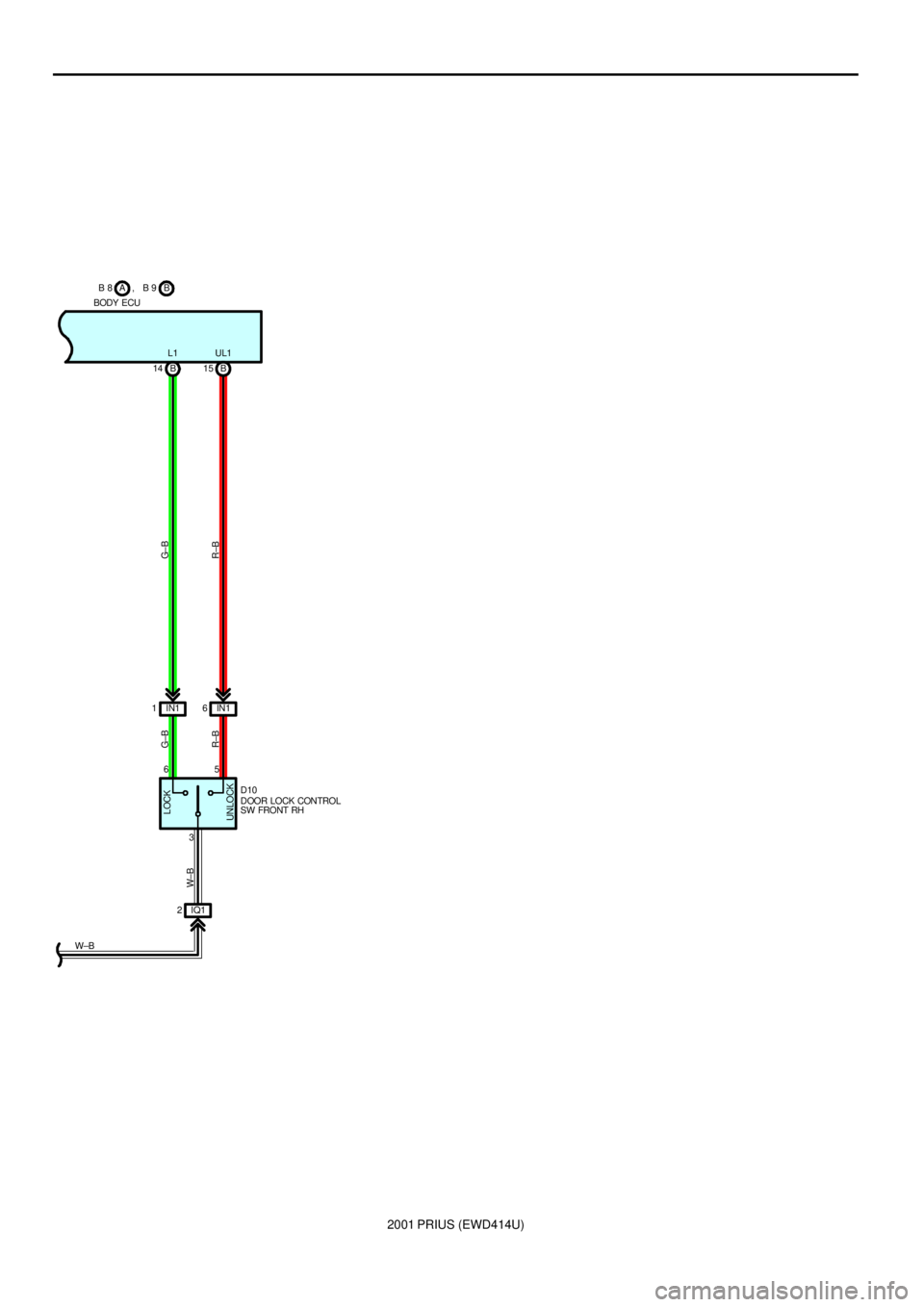
B 14 B15
IN1 1IN16
IQ1 2 65
3 L1 UL1
W±B
R±B G±B
W± BG± B
R±B
BODY ECUB B 8 , B 9A
UNLOCKLOCK
D10
DOOR LOCK CONTROL
SW FRONT RH
Page 136 of 1943
2001 PRIUS (EWD414U)
DOOR LOCK CONTROL
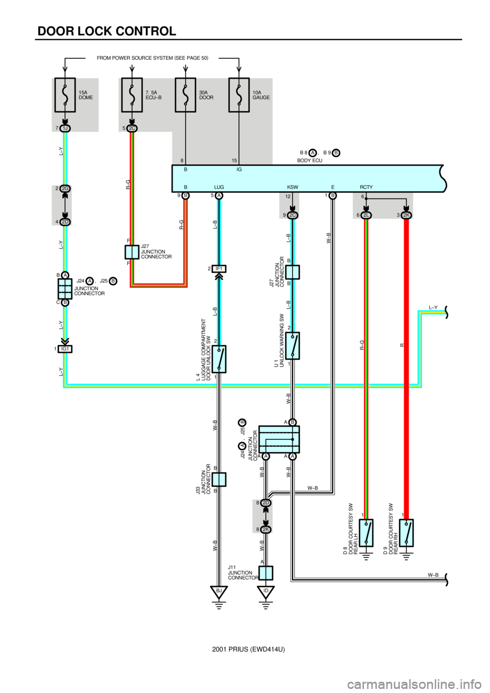
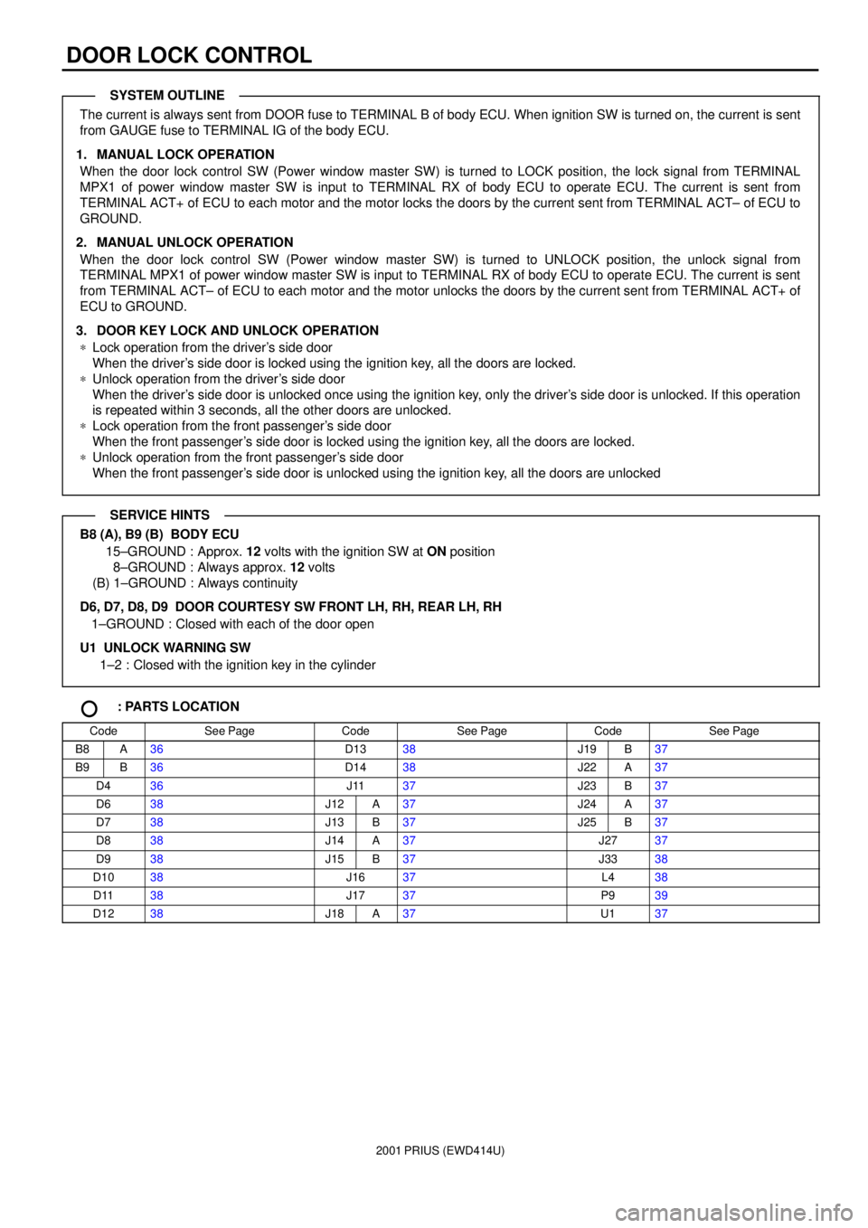
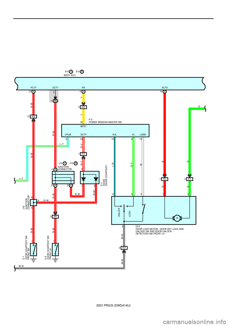
The current is always sent from DOOR fuse to TERMINAL B of body ECU. When ignition SW is turned on, the current is sent
from GAUGE fuse to TERMINAL IG of the body ECU.
1. MANUAL LOCK OPERATION
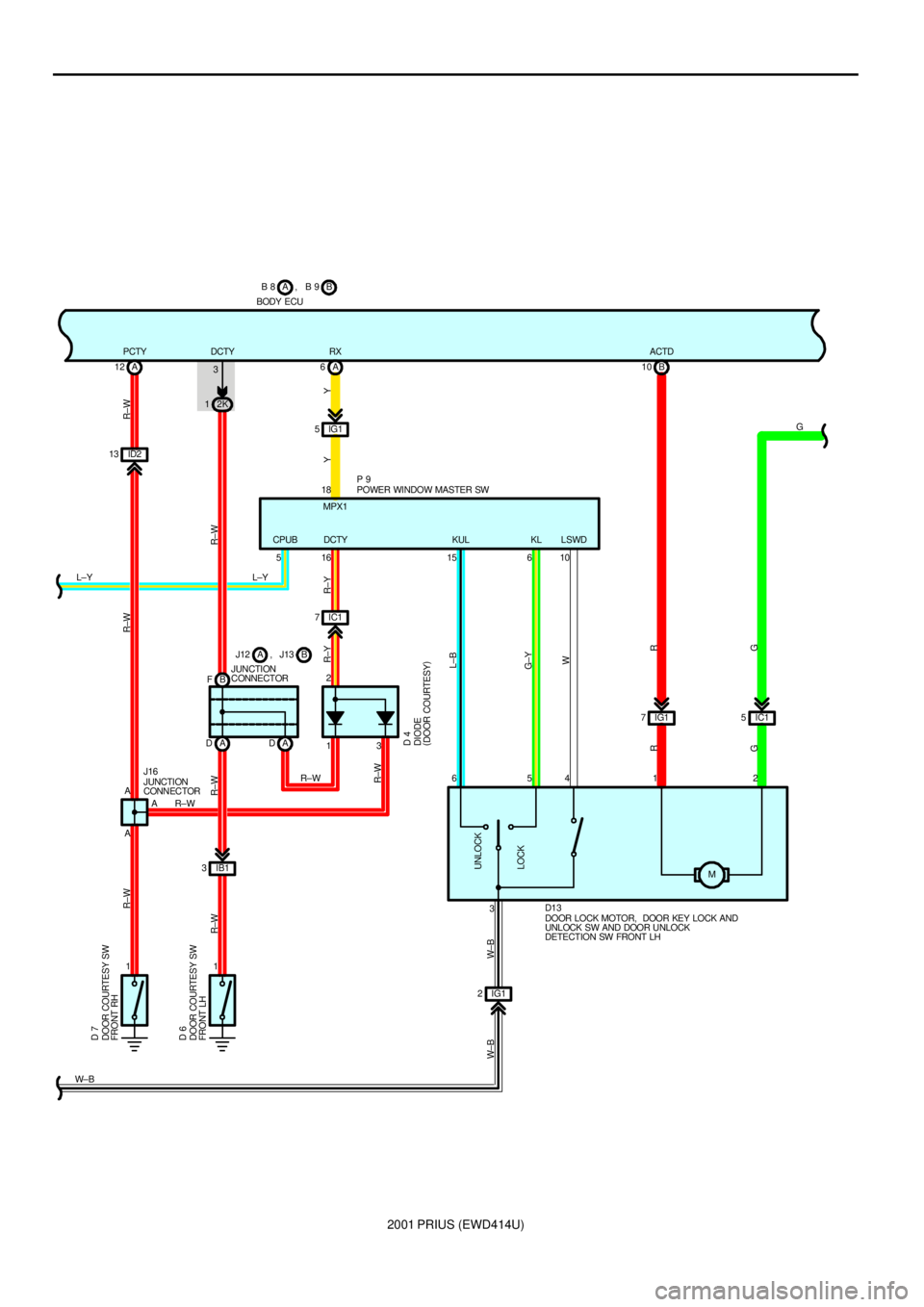
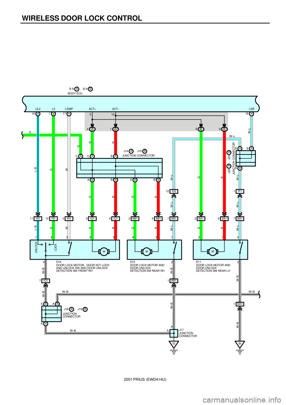
When the door lock control SW (Power window master SW) is turned to LOCK position, the lock signal from TERMINAL
MPX1 of power window master SW is input to TERMINAL RX of body ECU to operate ECU. The current is sent from
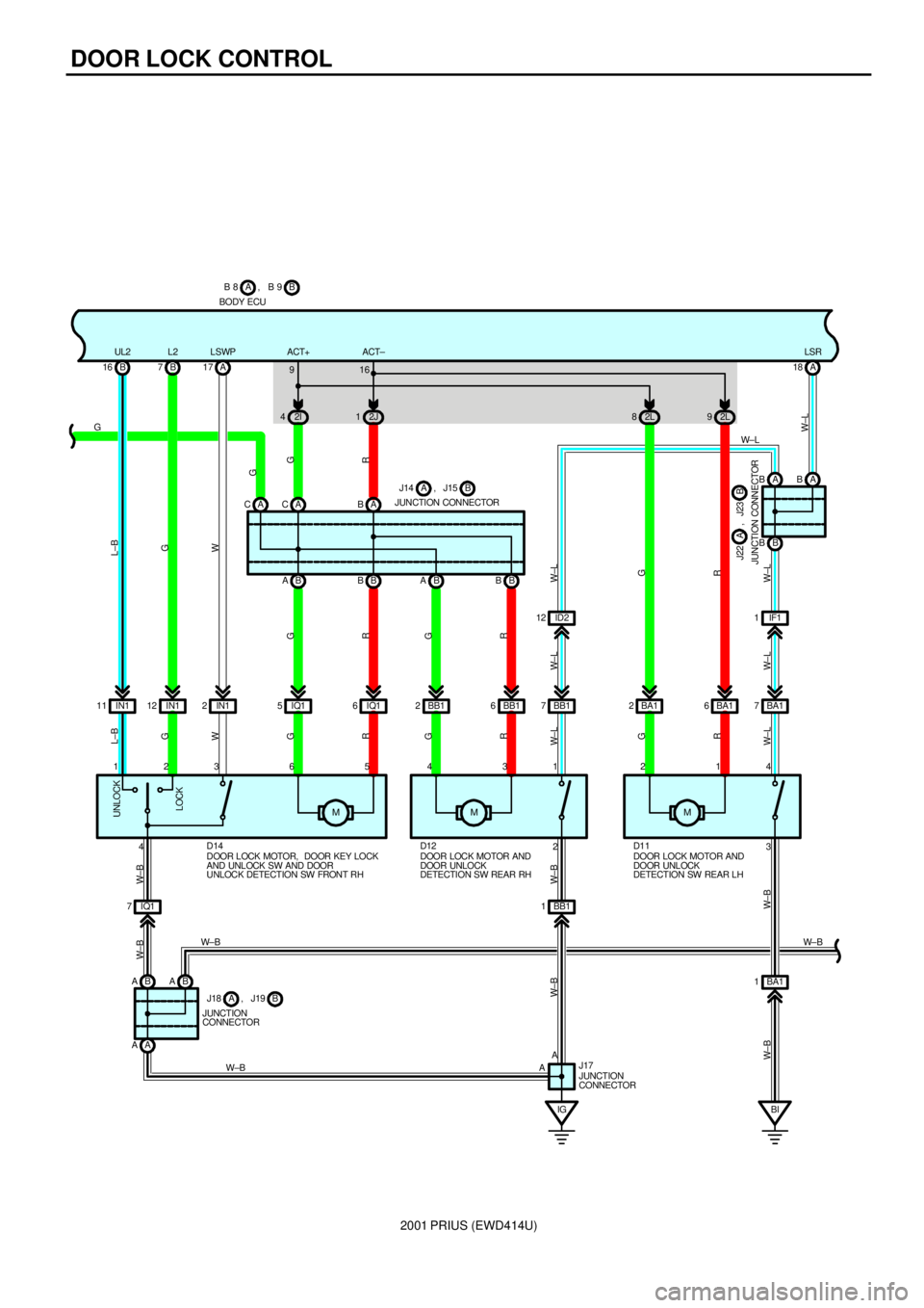
TERMINAL ACT+ of ECU to each motor and the motor locks the doors by the current sent from TERMINAL ACT± of ECU to
GROUND.
2. MANUAL UNLOCK OPERATION
When the door lock control SW (Power window master SW) is turned to UNLOCK position, the unlock signal from
TERMINAL MPX1 of power window master SW is input to TERMINAL RX of body ECU to operate ECU. The current is sent
from TERMINAL ACT± of ECU to each motor and the motor unlocks the doors by the current sent from TERMINAL ACT+ of
ECU to GROUND.
3. DOOR KEY LOCK AND UNLOCK OPERATION
*Lock operation from the driver's side door
When the driver's side door is locked using the ignition key, all the doors are locked.
*Unlock operation from the driver's side door
When the driver's side door is unlocked once using the ignition key, only the driver's side door is unlocked. If this operation
is repeated within 3 seconds, all the other doors are unlocked.
*Lock operation from the front passenger's side door
When the front passenger's side door is locked using the ignition key, all the doors are locked.
*Unlock operation from the front passenger's side door
When the front passenger's side door is unlocked using the ignition key, all the doors are unlocked
B8 (A), B9 (B) BODY ECU
15±GROUND : Approx. 12 volts with the ignition SW at ON position
8±GROUND : Always approx. 12 volts
(B) 1±GROUND : Always continuity
D6, D7, D8, D9 DOOR COURTESY SW FRONT LH, RH, REAR LH, RH
1±GROUND : Closed with each of the door open
U1 UNLOCK WARNING SW
1±2 : Closed with the ignition key in the cylinder
: PARTS LOCATION
CodeSee PageCodeSee PageCodeSee Page
B8A36D1338J19B37
B9B36D1438J22A37
D436J1137J23B37
D638J12A37J24A37
D738J13B37J25B37
D838J14A37J2737
D938J15B37J3338
D1038J1637L438
D1138J1737P939
D1238J18A37U137
SYSTEM OUTLINE
SERVICE HINTS
Page 137 of 1943
2001 PRIUS (EWD414U)
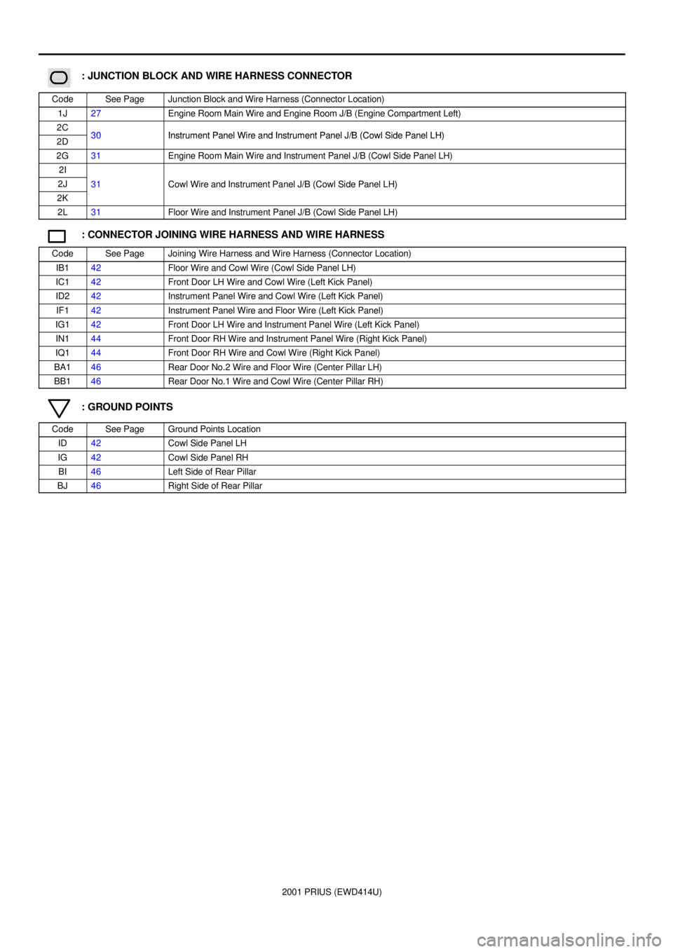
������ ���: JUNCTION BLOCK AND WIRE HARNESS CONNECTOR
CodeSee PageJunction Block and Wire Harness (Connector Location)
1J27Engine Room Main Wire and Engine Room J/B (Engine Compartment Left)
2C30Instrument Panel Wire and Instrument Panel J/B (Cowl Side Panel LH)2D30Instrument Panel Wire and Instrument Panel J/B (Cowl Side Panel LH)
2G31Engine Room Main Wire and Instrument Panel J/B (Cowl Side Panel LH)
2I
2J31Cowl Wire and Instrument Panel J/B (Cowl Side Panel LH)
2K
()
2L31Floor Wire and Instrument Panel J/B (Cowl Side Panel LH)
: CONNECTOR JOINING WIRE HARNESS AND WIRE HARNESS
CodeSee PageJoining Wire Harness and Wire Harness (Connector Location)
IB142Floor Wire and Cowl Wire (Cowl Side Panel LH)
IC142Front Door LH Wire and Cowl Wire (Left Kick Panel)
ID242Instrument Panel Wire and Cowl Wire (Left Kick Panel)
IF142Instrument Panel Wire and Floor Wire (Left Kick Panel)
IG142Front Door LH Wire and Instrument Panel Wire (Left Kick Panel)
IN144Front Door RH Wire and Instrument Panel Wire (Right Kick Panel)
IQ144Front Door RH Wire and Cowl Wire (Right Kick Panel)
BA146Rear Door No.2 Wire and Floor Wire (Center Pillar LH)
BB146Rear Door No.1 Wire and Cowl Wire (Center Pillar RH)
: GROUND POINTS
CodeSee PageGround Points Location
ID42Cowl Side Panel LH
IG42Cowl Side Panel RH
BI46Left Side of Rear Pillar
BJ46Right Side of Rear Pillar
Page 138 of 1943
2001 PRIUS (EWD414U)
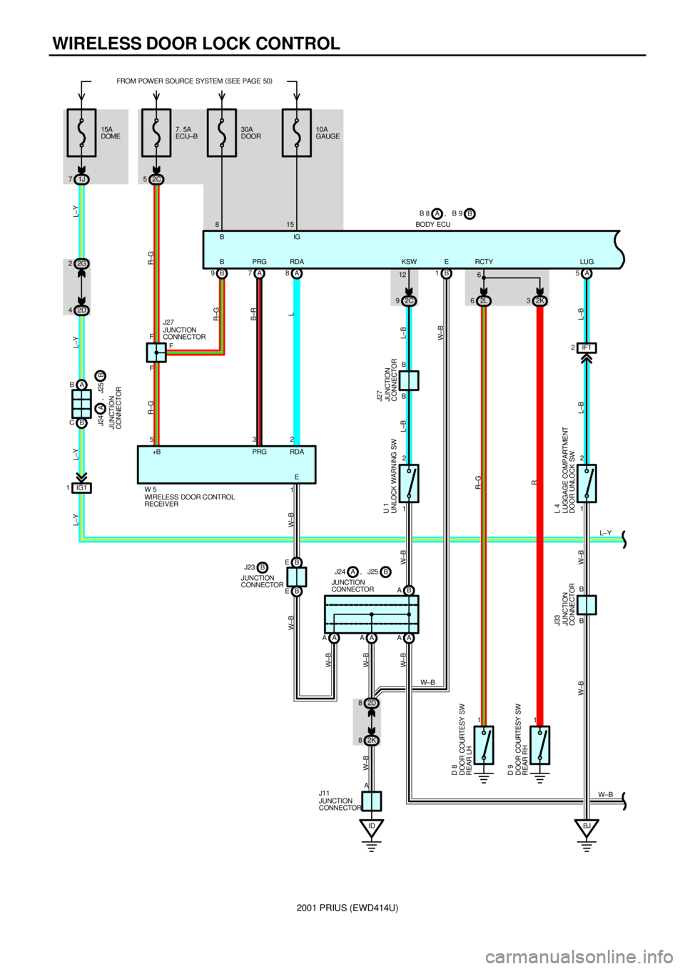
WIRELESS DOOR LOCK CONTROL
7. 5A
ECU±B FROM POWER SOURCE SYSTEM (
SEE PAGE 50)
2C 530A
DOOR
B 9A7A8
A AAA A AB A
ID 2D 8
2K 81 2B 1
2L 62K3
11 1B F6
2 3 5 F
B
A F8
E RDA PRG B
E
W±B W±B
R±G R±G
R±G
B±R
L
L±B
W±B L±B W±BW±B W±B
W± B
W± B
W± B
R±G
R W±B
2C 912BODY ECUB B 8 , B 9A
+B PRG RD A
UNLOCK WARNING SW U 1
JUNCTION
CONNECTOR J27
WIRELESS DOOR CONTROL
RECEIVER W 5JUNCTION
CONNECTOR J27
JUNCTION
CONNECTOR J11JUNCTION
CONNECTORB J24 , J25A
DOOR COURTESY SW
REAR LH D 8
DOOR COURTESY SW
REAR RH D 9
10A
GAUGE
15
A 5LUG
L±B
IF1 2
1 2
L 4
LUGGAGE COMPARTMENT
DOOR UNLOCK SW J33
JUNCTION
CONNECTOR
B B
L±B W±B W±B
BJ 15A
DOME
1J 7
2G 2
2D 4
A B
B C
IG1 1
L±Y L±Y L±Y L±Y
JUNCTION
CONNECTORB J24
A, J25
L±Y BIG
KSW RCTY
B E
B E JUNCTION
CONNECTORJ23 B
Page 139 of 1943
2001 PRIUS (EWD414U)
A 12
ID2 13
12K 1
A DAD B F
IB1 3
1A 6
IG1 5
IC1 7
LOCK UNLOCKM IG1 7B 10
IC1 5
IG1 2 13 16 15 6 10
A3
2 1 4 5 6
A18
3 AACTD RX PCTY
DCTY KUL KL LSWD
R±W
W± BG
R±W R±W
R±W
YY R±Y R±Y R±W R±W R±W
R±W
L±B
G±Y
W
R
GGR W± B W± B
R±W BODY ECUB B 8 , B 9A
2 JUNCTION
CONNECTORB J12 , J13APOWER WINDOW MASTER SW P 9
DIODE
(
DOOR COURTESY) D 4 DOOR COURTESY SW
FRONT LH D 6 DOOR COURTESY SW
FRONT RH D 7
DOOR LOCK MOTOR, DOOR KEY LOCK AND
UNLOCK SW AND DOOR UNLOCK
DETECTION SW FRONT LH D13 MPX1
J16
JUNCTION
CONNECTOR
5 CPUB
L±Y
L±YDCTY
Page 140 of 1943
2001 PRIUS (EWD414U)
WIRELESS DOOR LOCK CONTROL
A CACAB
B B B A B B B A2I 42J1
IQ1 5IQ16 BB12 BB16
MM
IG BB1 1
A AB ABA IQ1 7M 2L 82L9
BA1 2 BA16 BB1 7ID2 12B BA BABA 18
BA1 7IF1 1 B 16 B7A17
IN1 2 IN1 12 IN1 11
42
A
A4 1 2 1 3 4 5 6 3 2 1 GUL2 L2 LSWPLSR
W± B W± B
W±BW± L
W± LR G W± LR GR G WG L±B
W± B
W± B W± B
W± B
W±L W± L
W±L R G W±L W± LR GR G
R G G WG L±B
916
JUNCTION CONNECTORB J14 , J15A
JUNCTION CONNECTORB J22 A , J23
BI BA1 13
W± B W± B
JUNCTION
CONNECTORB J18 , J19A
JUNCTION
CONNECTOR J17 DOOR LOCK MOTOR, DOOR KEY LOCK
AND UNLOCK SW AND DOOR UNLOCK
DETECTION SW FRONT RH D14
DOOR LOCK MOTOR AND
DOOR UNLOCK
DETECTION SW REAR RH D12
DOOR LOCK MOTOR AND
DOOR UNLOCK
DETECTION SW REAR LH D11 AB 9, B 8 B
BODY ECU
LOCK UNLOCK
ACT+ ACT±