TOYOTA PRIUS 2001 Service Repair Manual
Manufacturer: TOYOTA, Model Year: 2001, Model line: PRIUS, Model: TOYOTA PRIUS 2001Pages: 1943, PDF Size: 18.26 MB
Page 1931 of 1943
I17965
I17967
I17956
AC±70
± AIR CONDITIONINGCONDENSER FAN
2001 PRIUS (RM778U)
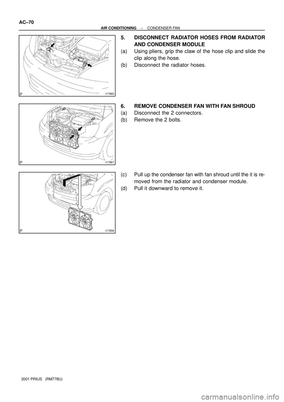
5. DISCONNECT RADIATOR HOSES FROM RADIATOR
AND CONDENSER MODULE
(a) Using pliers, grip the claw of the hose clip and slide the
clip along the hose.
(b) Disconnect the radiator hoses.
6. REMOVE CONDENSER FAN WITH FAN SHROUD
(a) Disconnect the 2 connectors.
(b) Remove the 2 bolts.
(c) Pull up the condenser fan with fan shroud until the it is re-
moved from the radiator and condenser module.
(d) Pull it downward to remove it.
Page 1932 of 1943
AC36J±01
I17991
I18015
I18034
I18035
I18036 : Bulb
AC±76
± AIR CONDITIONINGHEATER CONTROL ASSEMBLY
2001 PRIUS (RM778U)
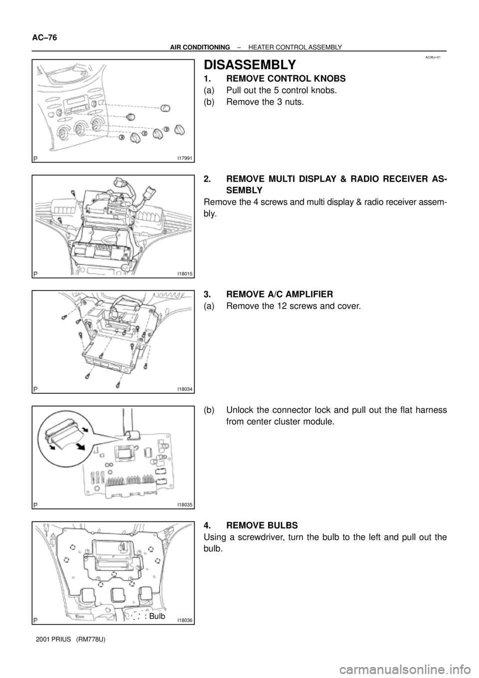
DISASSEMBLY
1. REMOVE CONTROL KNOBS
(a) Pull out the 5 control knobs.
(b) Remove the 3 nuts.
2. REMOVE MULTI DISPLAY & RADIO RECEIVER AS-
SEMBLY
Remove the 4 screws and multi display & radio receiver assem-
bly.
3. REMOVE A/C AMPLIFIER
(a) Remove the 12 screws and cover.
(b) Unlock the connector lock and pull out the flat harness
from center cluster module.
4. REMOVE BULBS
Using a screwdriver, turn the bulb to the left and pull out the
bulb.
Page 1933 of 1943
I18037
± AIR CONDITIONINGHEATER CONTROL ASSEMBLY
AC±77
2001 PRIUS (RM778U)
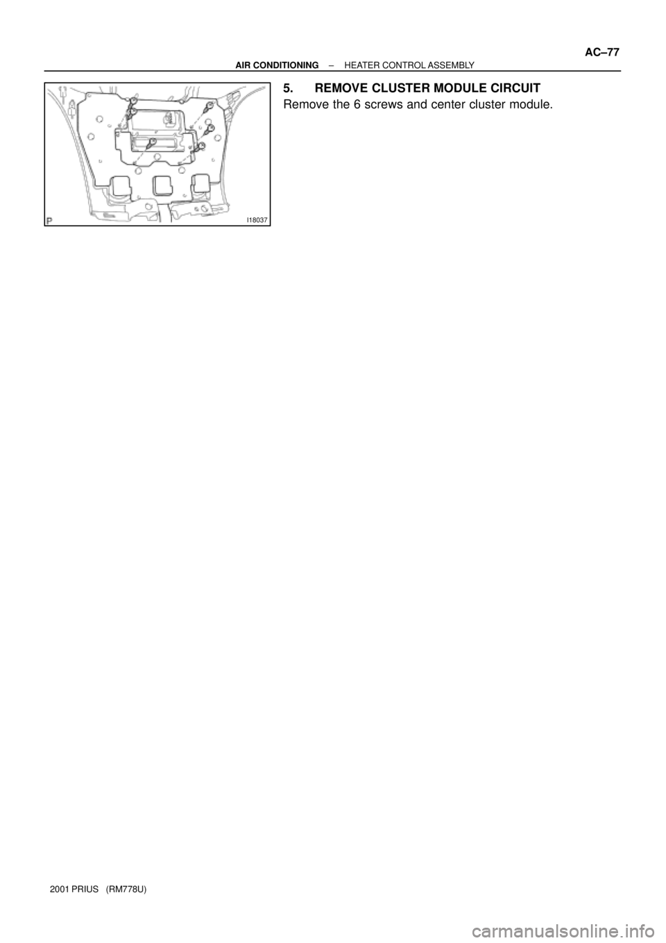
5. REMOVE CLUSTER MODULE CIRCUIT
Remove the 6 screws and center cluster module.
Page 1934 of 1943
AC36K±01
I18038 : Bulb
5
10
I07872
I17978
1
7
AC±78
± AIR CONDITIONINGHEATER CONTROL ASSEMBLY
2001 PRIUS (RM778U)
INSPECTION
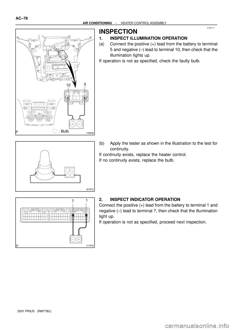
1. INSPECT ILLUMINATION OPERATION
(a) Connect the positive (+) lead from the battery to terminal
5 and negative (±) lead to terminal 10, then check that the
illumination lights up.
If operation is not as specified, check the faulty bulb.
(b) Apply the tester as shown in the illustration to the test for
continuity.
If continuity exists, replace the heater control.
If no continuity exists, replace the bulb.
2. INSPECT INDICATOR OPERATION
Connect the positive (+) lead from the battery to terminal 1 and
negative (±) lead to terminal 7, then check that the illumination
light up.
If operation is not as specified, proceed next inspection.
Page 1935 of 1943
I18039
1
3
2 Dry Cell Batteries
I18040
1
5
2 Dry Cell Batteries
I18043
1 15
2 Dry Cell Batteries
I18044
6 8 14
13
± AIR CONDITIONINGHEATER CONTROL ASSEMBLY
AC±79
2001 PRIUS (RM778U)
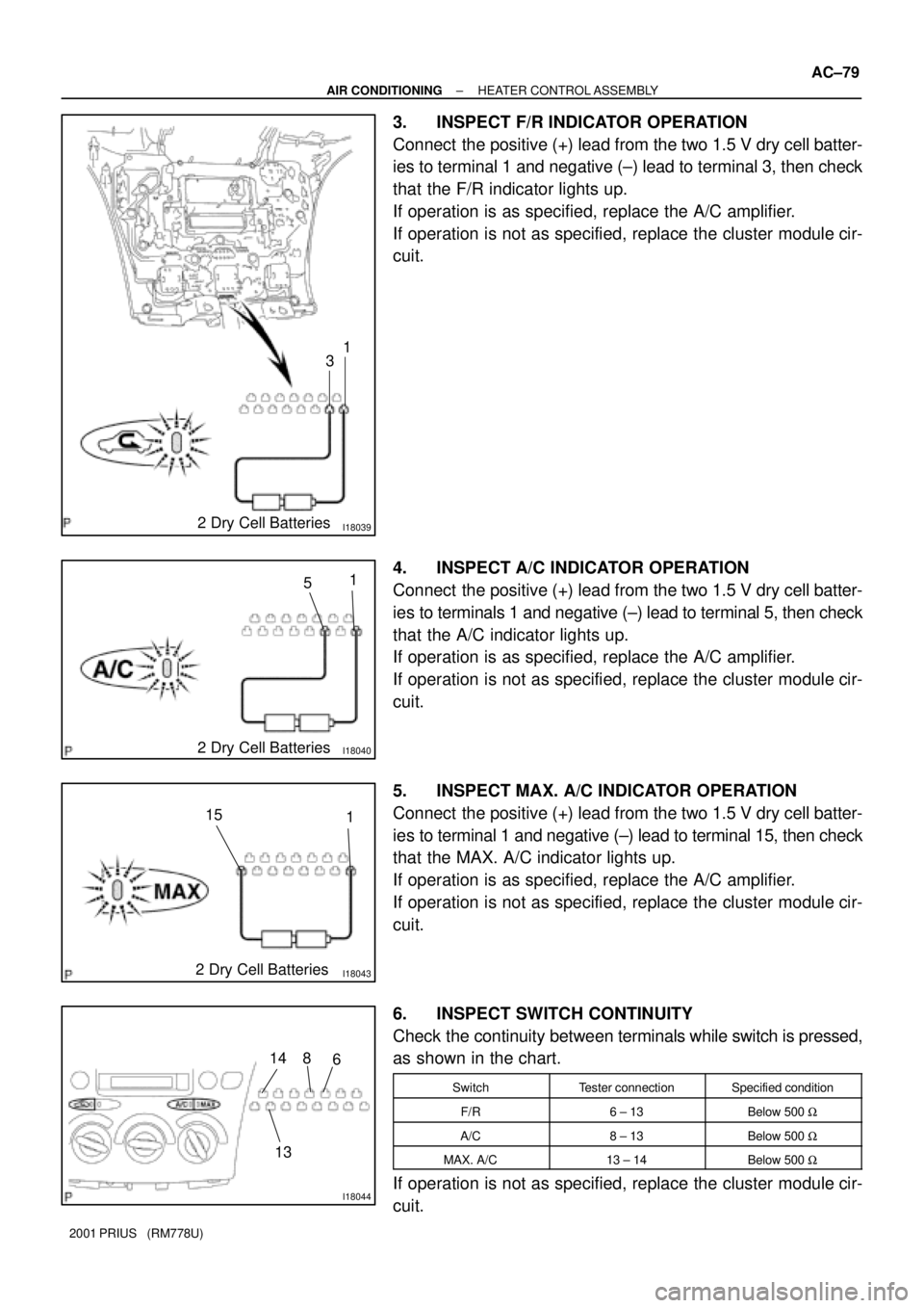
3. INSPECT F/R INDICATOR OPERATION
Connect the positive (+) lead from the two 1.5 V dry cell batter-
ies to terminal 1 and negative (±) lead to terminal 3, then check
that the F/R indicator lights up.
If operation is as specified, replace the A/C amplifier.
If operation is not as specified, replace the cluster module cir-
cuit.
4. INSPECT A/C INDICATOR OPERATION
Connect the positive (+) lead from the two 1.5 V dry cell batter-
ies to terminals 1 and negative (±) lead to terminal 5, then check
that the A/C indicator lights up.
If operation is as specified, replace the A/C amplifier.
If operation is not as specified, replace the cluster module cir-
cuit.
5. INSPECT MAX. A/C INDICATOR OPERATION
Connect the positive (+) lead from the two 1.5 V dry cell batter-
ies to terminal 1 and negative (±) lead to terminal 15, then check
that the MAX. A/C indicator lights up.
If operation is as specified, replace the A/C amplifier.
If operation is not as specified, replace the cluster module cir-
cuit.
6. INSPECT SWITCH CONTINUITY
Check the continuity between terminals while switch is pressed,
as shown in the chart.
SwitchTester connectionSpecified condition
F/R6 ± 13Below 500 W
A/C8 ± 13Below 500 W
MAX. A/C13 ± 14Below 500 W
If operation is not as specified, replace the cluster module cir-
cuit.
Page 1936 of 1943
I180463 Dry Cell Batteries9
12 13
I180473 Dry Cell Batteries9
11 13
COOL
WARM
I180453 Dry Cell Batteries9
10 13 M1
M2
AC±80
± AIR CONDITIONINGHEATER CONTROL ASSEMBLY
2001 PRIUS (RM778U)
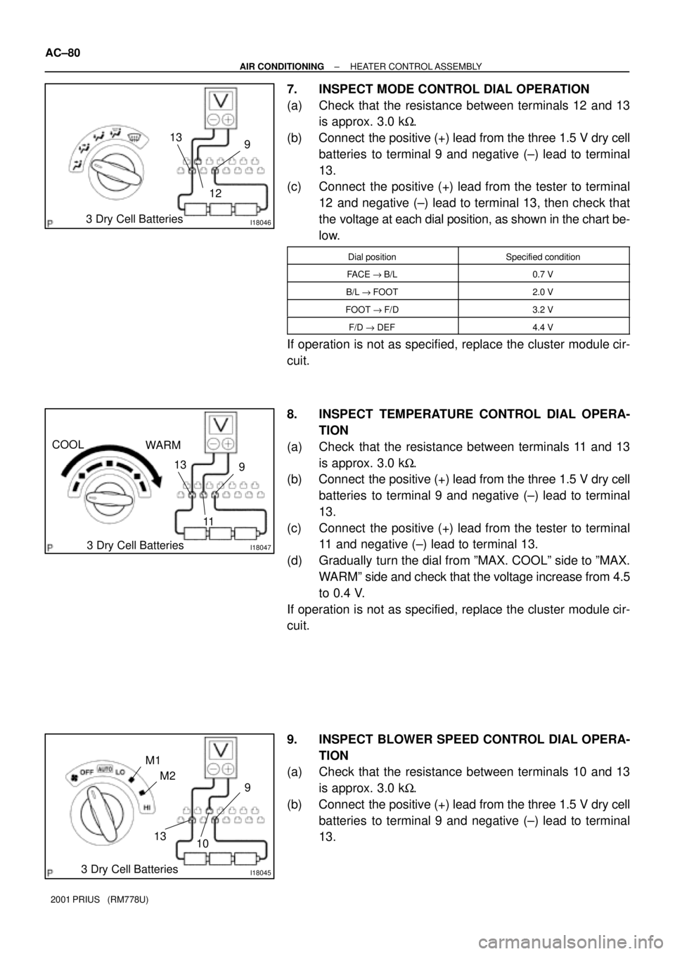
7. INSPECT MODE CONTROL DIAL OPERATION
(a) Check that the resistance between terminals 12 and 13
is approx. 3.0 kW.
(b) Connect the positive (+) lead from the three 1.5 V dry cell
batteries to terminal 9 and negative (±) lead to terminal
13.
(c) Connect the positive (+) lead from the tester to terminal
12 and negative (±) lead to terminal 13, then check that
the voltage at each dial position, as shown in the chart be-
low.
Dial positionSpecified condition
FACE "B/L0.7 V
B/L "FOOT2.0 V
FOOT "F/D3.2 V
F/D " DEF4.4 V
If operation is not as specified, replace the cluster module cir-
cuit.
8. INSPECT TEMPERATURE CONTROL DIAL OPERA-
TION
(a) Check that the resistance between terminals 11 and 13
is approx. 3.0 kW.
(b) Connect the positive (+) lead from the three 1.5 V dry cell
batteries to terminal 9 and negative (±) lead to terminal
13.
(c) Connect the positive (+) lead from the tester to terminal
11 and negative (±) lead to terminal 13.
(d) Gradually turn the dial from ºMAX. COOLº side to ºMAX.
WARMº side and check that the voltage increase from 4.5
to 0.4 V.
If operation is not as specified, replace the cluster module cir-
cuit.
9. INSPECT BLOWER SPEED CONTROL DIAL OPERA-
TION
(a) Check that the resistance between terminals 10 and 13
is approx. 3.0 kW.
(b) Connect the positive (+) lead from the three 1.5 V dry cell
batteries to terminal 9 and negative (±) lead to terminal
13.
Page 1937 of 1943

± AIR CONDITIONINGHEATER CONTROL ASSEMBLY
AC±81
2001 PRIUS (RM778U)
(c) Connect the positive (+) lead from the tester to terminal
10 and negative (±) lead to terminal 13 then check that the
voltage at each dial position, as shown in the chart below.
Dial positionSpecified condition
OFF "AUTO1.45 V
AUTO "LO2.25 V
LO "M13.05 V
M1 " M23.85 V
M2 " H14.65 V
If operation is not as specified, replace the cluster module cir-
cuit.
Page 1938 of 1943
I15478
Hybrid Vehicle
Control ECU
C14
Cruise Control SW (Comb. SW)
A
W±B
5
LCCS 16
H14
CRUISE
CCS RES/
ACC
SET/
COAST
CANCEL
ECC
J17
J/C
IG A W±B
J18A
J194
± DIAGNOSTICSCRUISE CONTROL SYSTEM
DI±661
2001 PRIUS (RM778U)
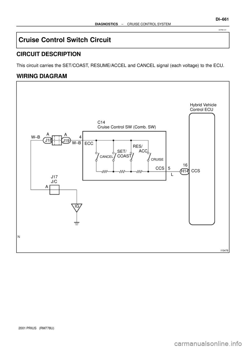
Cruise Control Switch Circuit
CIRCUIT DESCRIPTION
This circuit carries the SET/COAST, RESUME/ACCEL and CANCEL signal (each voltage) to the ECU.
WIRING DIAGRAM
DI7NK±01
Page 1939 of 1943
I19096
ON
CCS
(+) (±)
DI±662
± DIAGNOSTICSCRUISE CONTROL SYSTEM
2001 PRIUS (RM778U)
INSPECTION PROCEDURE
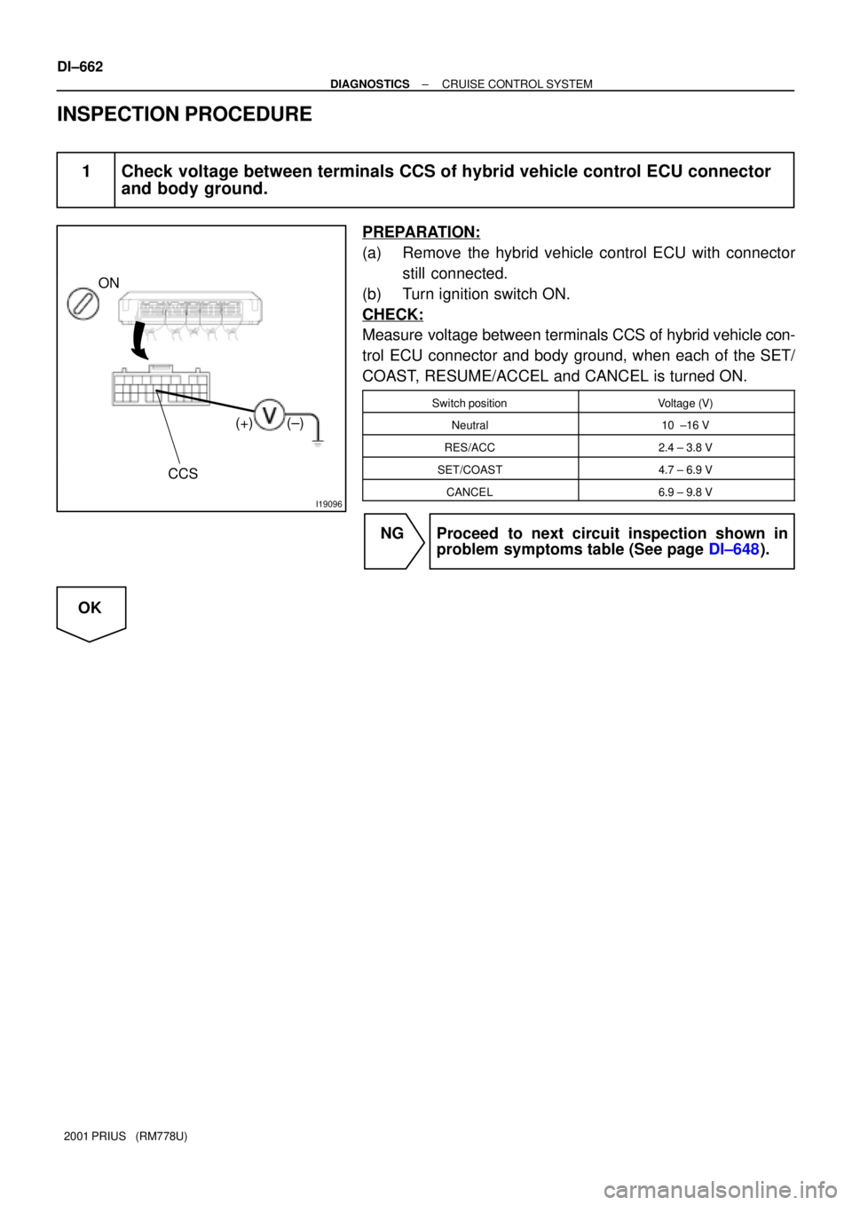
1 Check voltage between terminals CCS of hybrid vehicle control ECU connector
and body ground.
PREPARATION:
(a) Remove the hybrid vehicle control ECU with connector
still connected.
(b) Turn ignition switch ON.
CHECK:
Measure voltage between terminals CCS of hybrid vehicle con-
trol ECU connector and body ground, when each of the SET/
COAST, RESUME/ACCEL and CANCEL is turned ON.
Switch positionVoltage (V)
Neutral10 ±16 V
RES/ACC2.4 ± 3.8 V
SET/COAST4.7 ± 6.9 V
CANCEL6.9 ± 9.8 V
NG Proceed to next circuit inspection shown in
problem symptoms table (See page DI±648).
OK
Page 1940 of 1943
I05156
RES/ACC
CANCEL
SET/COAST
4
3
I05126
CRUISE MAIN
Switch
43
± DIAGNOSTICSCRUISE CONTROL SYSTEM
DI±663
2001 PRIUS (RM778U)
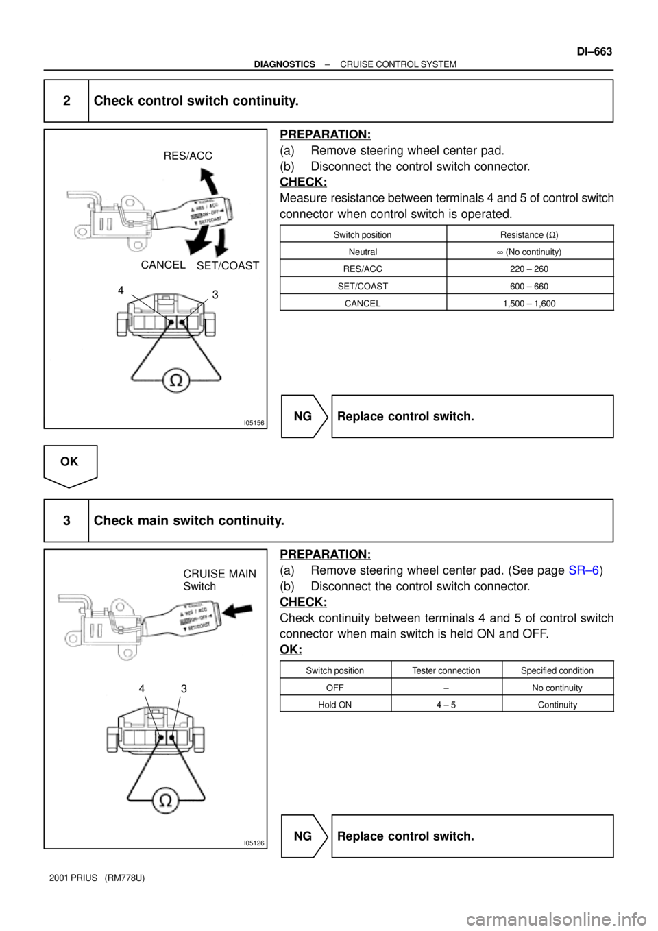
2 Check control switch continuity.
PREPARATION:
(a) Remove steering wheel center pad.
(b) Disconnect the control switch connector.
CHECK:
Measure resistance between terminals 4 and 5 of control switch
connector when control switch is operated.
Switch positionResistance (W)
Neutral8 (No continuity)
RES/ACC220 ± 260
SET/COAST600 ± 660
CANCEL1,500 ± 1,600
NG Replace control switch.
OK
3 Check main switch continuity.
PREPARATION:
(a) Remove steering wheel center pad. (See page SR±6)
(b) Disconnect the control switch connector.
CHECK:
Check continuity between terminals 4 and 5 of control switch
connector when main switch is held ON and OFF.
OK:
Switch positionTester connectionSpecified condition
OFF±No continuity
Hold ON4 ± 5Continuity
NG Replace control switch.