TOYOTA PRIUS 2001 Service Manual PDF
Manufacturer: TOYOTA, Model Year: 2001, Model line: PRIUS, Model: TOYOTA PRIUS 2001Pages: 1943, PDF Size: 18.26 MB
Page 71 of 1943
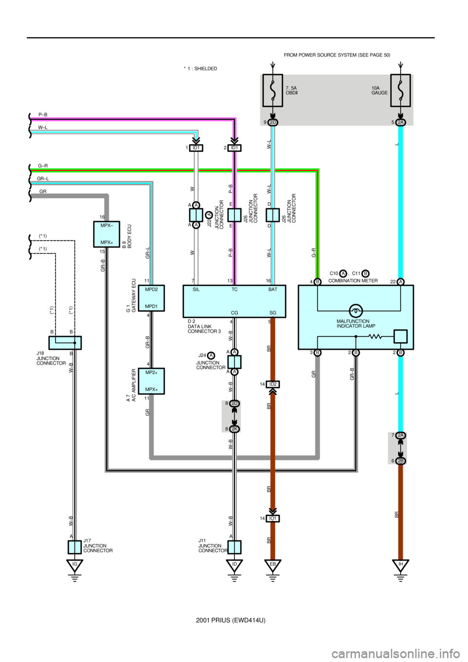
2001 PRIUS (EWD414U)
IGB 3B2 B 4 7. 5A
OBDII
2D 9
EB IO1 14ID2 14 15
B
115 4ED
4 11 16ED
BB
A71316FROM POWER SOURCE SYSTEM (
SEE PAGE 50)
JUNCTION
CONNECTOR J26 JUNCTION
CONNECTOR J26 BODY ECU B 8
A/C AMPLIFIER A 7
GATEWAY ECU G 1
DATA LINK
CONNECTOR 3 D 2
JUNCTION
CONNECTOR J18
W±L W
P±B
W±L W
P±B
W± L BR BR BR BR
GR
GR± B GR GR±B GR±L(
*1)
(
*1)
W±B W± B
G± R GR±B
GR GR± LG±R W±LP±B
(
*1) (
*1)
JUNCTION
CONNECTOR J17MPX+ MPD1 MPX+
SG CGBAT TC SIL MPD2 MPX±
MP2+
ID 2K 82D 8
W± B W± B
A
JUNCTION
CONNECTOR J11
W± B W± B
4 ID1 1ID12 * 1 : SHIELDED
COMBINATION METERB C10 , C11A10A
GAUGE
2A 5
L
A 22
MALFUNCTION
INDICATOR LAMP
B 2
IH 2A 7
2B 6
L BR
A A
A A A A
A A
JUNCTION
CONNECTORJ22 A
JUNCTION
CONNECTORJ24 A
Page 72 of 1943

2001 PRIUS (EWD414U)
ENGINE CONTROL
This system utilizes an engine control module and maintains overall control of the engine, transmission and so on. An outline
of the engine control is explained here.
1. INPUT SIGNALS
(1) Engine coolant temp. signal circuit
The engine coolant temp. sensor detects the engine coolant temp. and has a built±in thermistor with a resistance which
varies according to the engine coolant temp. thus the engine coolant temp. is input in the form of a control signal into
TERMINAL THW of the engine control module.
(2) Intake air temp. signal circuit
The intake air temp. sensor is installed in the mass air flow meter and detects the intake air temp., which is input as a
control signal into TERMINAL THA of the engine control module.
(3) Oxygen sensor signal circuit
The oxygen density in the exhaust gases is detected and input as a control signal into TERMINALS OX1A and OX1B of
the engine control module.
(4) RPM signal circuit
Camshaft position and crankshaft position are detected by the camshaft position sensor and crankshaft position sensor.
Camshaft position is input as a control signal to TERMINAL G2 of the engine control module, and engine RPM is input
into TERMINAL NE+.
(5) Throttle signal circuit
The throttle position sensor detects the throttle valve opening angle, which is input as a control signal into TERMINALS
VTA and VTA2 of the engine control module.
(6) Vehicle speed signal circuit
The vehicle speed signal from brake ECU, detects the vehicle speed and inputs a control signal into TERMINAL SPD of
the engine control module via the combination meter.
(7) Battery signal circuit
Voltage is constantly applied to TERMINAL BATT of the engine control module. When the ignition SW is turned on, the
voltage for engine control module start±up power supply is applied to TERMINAL +B of the engine control module via
EFI relay.
(8) Engine knock signal circuit
Engine knocking is detected by knock sensor and the signal is input into TERMINAL KNK1 of the engine control module
as a control signal.
2. CONTROL SYSTEM
*SFI system
The SFI system monitors the engine condition through the signals, which are input from each sensor to the engine
control module. The best fuel injection volume is decided based on this data and the program memorized by the engine
control module, and the control signal is output to TERMINALS #10, #20, #30 and #40 of the engine control module to
operate the injector. (Inject the fuel). The SFI system produces control of fuel injection operation by the engine control
module in response to the driving conditions.
*ESA system
The ESA system monitors the engine condition through the signals, which are input to the engine control module from
each sensor. The best ignition timing is detected according to this data and the memorized data in the engine control
module, and the control signal is output to TERMINALS IGT1, IGT2, IGT3 and IGT4. This signal controls the ignition coil
and igniter to provide the best ignition timing for the driving conditions.
*Fuel pump control system
The engine control module operation outputs to TERMINAL FC and controls the CIR OPN relay. Thus controls the fuel
pump drive speed in response to conditions.
3. DIAGNOSIS SYSTEM
With the diagnosis system, when there is a malfunctioning in the engine control module signal system, the malfunction
system is recorded in the memory. The malfunctioning system can then be found by reading the display (Code) of the
malfunction indicator lamp.
4. FAIL±SAFE SYSTEM
When a malfunction occurs in any system, if there is a possibility of engine trouble being caused by continued control based
on the signals from that system, the fail±safe system either controls the system by using data (Standard values) recorded in
the engine control module memory or else stops the engine.
SYSTEM OUTLINE
Page 73 of 1943
2001 PRIUS (EWD414U)
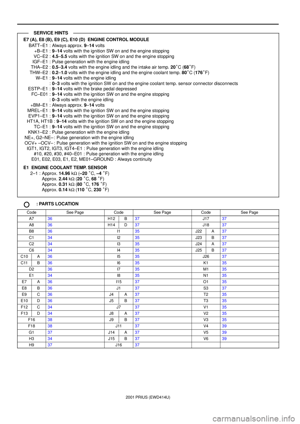
E7 (A), E8 (B), E9 (C), E10 (D) ENGINE CONTROL MODULE
BATT±E1 : Always approx. 9±14 volts
+B±E1 :9±14 volts with the ignition SW on and the engine stopping
VC±E2 :4.5±5.5 volts with the ignition SW on and the engine stopping
IGF±E1 : Pulse generation with the engine idling
THA±E2 :0.5±3.4 volts with the engine idling and the intake air temp. 20°C (68°F)
THW±E2 :0.2±1.0 volts with the engine idling and the engine coolant temp. 80°C (176°F)
W±E1 :9±14 volts with the engine idling
:0±3 volts with the ignition SW on and the engine coolant temp. sensor connector disconnects
ESTP±E1 :9±14 volts with the brake pedal depressed
FC±E01 :9±14 volts with the ignition SW on and the engine stopping
:0±3 volts with the engine idling
+BM±E1 : Always approx. 9±14 volts
MREL±E1 :9±14 volts with the ignition SW on and the engine stopping
EVP1±E1 :9±14 volts with the ignition SW on and the engine stopping
HT1A, HT1B :9±14 volts with the ignition SW on and the engine stopping
TC±E1 :9±14 volts with the ignition SW on and the engine stopping
KNK1±E2 : Pulse generation with the engine idling
NE+, G2±NE± : Pulse generation with the engine idling
OCV+ ±OCV± : Pulse generation with the ignition SW on and the engine stopping
IGT1, IGT2, IGT3, IGT4±E1 : Pulse generation with the engine idling
#10, #20, #30, #40±E01 : Pulse generation with the engine idling
E01, E02, E03, E1, E2, ME01±GROUND : Always continuity
E1 ENGINE COOLANT TEMP. SENSOR
2±1 : Approx. 14.96 kW (±20 °C, ±4 °F)
Approx. 2.44 kW (20 °C, 68 °F)
Approx. 0.31 kW (80 °C, 176 °F)
Approx. 0.14 kW (110 °C, 230 °F)
: PARTS LOCATION
CodeSee PageCodeSee PageCodeSee Page
A736H12B37J1737
A836H14D37J1837
B836I135J22A37
C134I235J23B37
C234I335J24A37
C634I435J25B37
C10A36I535J2637
C11B36I635K135
D236I735M135
E134I835N135
E7A36I1537O135
E8B36J137S337
E9C36J4A37T235
E10D36J5B37T335
F12C34J737V135
F13D34J8A37V235
F1638J9B37V335
F1838J1137V439
G137J14A37V539
H334J15B37V639
H937J1637
SERVICE HINTS
Page 74 of 1943
2001 PRIUS (EWD414U)
ENGINE CONTROL
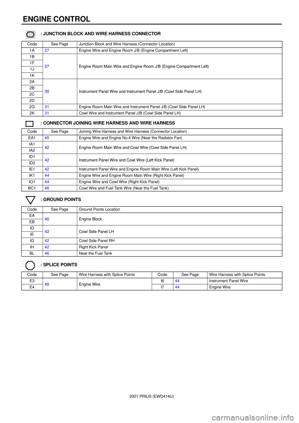
������ ���: JUNCTION BLOCK AND WIRE HARNESS CONNECTOR
CodeSee PageJunction Block and Wire Harness (Connector Location)
1A27Engine Wire and Engine Room J/B (Engine Compartment Left)
1B
1F27Engine Room Main Wire and Engine Room J/B (Engine Compartment Left)1J27Engine Room Main Wire and Engine Room J/B (Engine Compartment Left)
1K
2A
2B30Instrument Panel Wire and Instrument Panel J/B (Cowl Side Panel LH)2C30Instrument Panel Wire and Instrument Panel J/B (Cowl Side Panel LH)
2D
2G31Engine Room Main Wire and Instrument Panel J/B (Cowl Side Panel LH)
2K31Cowl Wire and Instrument Panel J/B (Cowl Side Panel LH)
: CONNECTOR JOINING WIRE HARNESS AND WIRE HARNESS
CodeSee PageJoining Wire Harness and Wire Harness (Connector Location)
EA140Engine Wire and Engine No.4 Wire (Near the Radiator Fan)
IA142Engine Room Main Wire and Cowl Wire (Cowl Side Panel LH)IA242Engine Room Main Wire and Cowl Wire (Cowl Side Panel LH)
ID142Instrument Panel Wire and Cowl Wire (Left Kick Panel)ID242Instrument Panel Wire and Cowl Wire (Left Kick Panel)
IE142Instrument Panel Wire and Engine Room Main Wire (Left Kick Panel)
IK144Engine Wire and Engine Room Main Wire (Right Kick Panel)
IO144Engine Wire and Cowl Wire (Right Kick Panel)
BC146Cowl Wire and Fuel Tank Wire (Near the Fuel Tank)
: GROUND POINTS
CodeSee PageGround Points Location
EA40Engine BlockEB40Engine Block
ID42Cowl Side Panel LHIE42Cowl Side Panel LH
IG42Cowl Side Panel RH
IH42Right Kick Panel
BL46Near the Fuel Tank
: SPLICE POINTS
CodeSee PageWire Harness with Splice PointsCodeSee PageWire Harness with Splice Points
E340Engine WireI644Instrument Panel Wire
E440Engine WireI744Engine Wire
Page 75 of 1943

2001 PRIUS (EWD414U)
MEMO
Page 76 of 1943
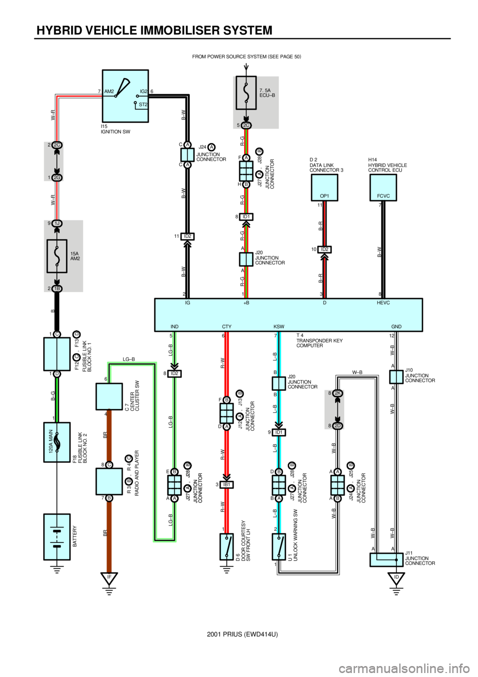
2001 PRIUS (EWD414U)
HYBRID VEHICLE IMMOBILISER SYSTEM
7. 5A
ECU±B FROM POWER SOURCE SYSTEM (
SEE PAGE 50)
2C 5
A A AA F
B H
5JUNCTION
CONNECTOR J20
JUNCTION
CONNECTOR J11 1
12
R±G R±G R±G LG±B
W±B W± B W±B
+B HEVC
IND
JUNCTION
CONNECTORB J27 A , J28
ID2 10 ID2 11 76
15A
AM2
1B 21J 92C 2
2G 1
D 1C 1
120A MAIN
1AM2 IG2
ST2
IFC 8
B 7B E
A A
JUNCTION
CONNECTORB J27 A , J28
JUNCTION
CONNECTORB J27 A , J28
B F
A D
JUNCTION
CONNECTORB J12 A , J13
B D
A B
JUNCTION
CONNECTORB J27 A , J28
A A
B A
JUNCTION
CONNECTORB J24 A , J25
ID A A
2D 8
1 2ID1 9B B
IB1 3
1 ID2 8
JUNCTION
CONNECTOR J10
JUNCTION
CONNECTOR J20
46711 7
238
6DATA LINK
CONNECTOR 3 D 2
HYBRID VEHICLE
CONTROL ECU H14
CENTER
CLUSTER SW C 7
DOOR COURTESY
SW FRONT LH D 6
UNLOCK WARNING SW U 1RADIO AND PLAYERC R 3 B , R 4FUSIBLE LINK
BLOCK NO. 1D F1 2 C , F13 BATTERYB±G B W±R W±R
B±W B±W B±W
B±R
B±WB±R R±W
L±B
W±BL±B L±B L±B
W±BR±W R±WLG±B BR BR
LG±B
2K 8
A IG D
KSW CTY
LG±B
FUSIBLE LINK
BLOCK NO. 2 F18
W±B
W± B ID1 8
R±G
IGNITION SW I15
OP1 FC VC
GND
TRANSPONDER KEY
COMPUTER T 4 A C
A CJUNCTION
CONNECTORJ24 A
Page 77 of 1943
2001 PRIUS (EWD414U)
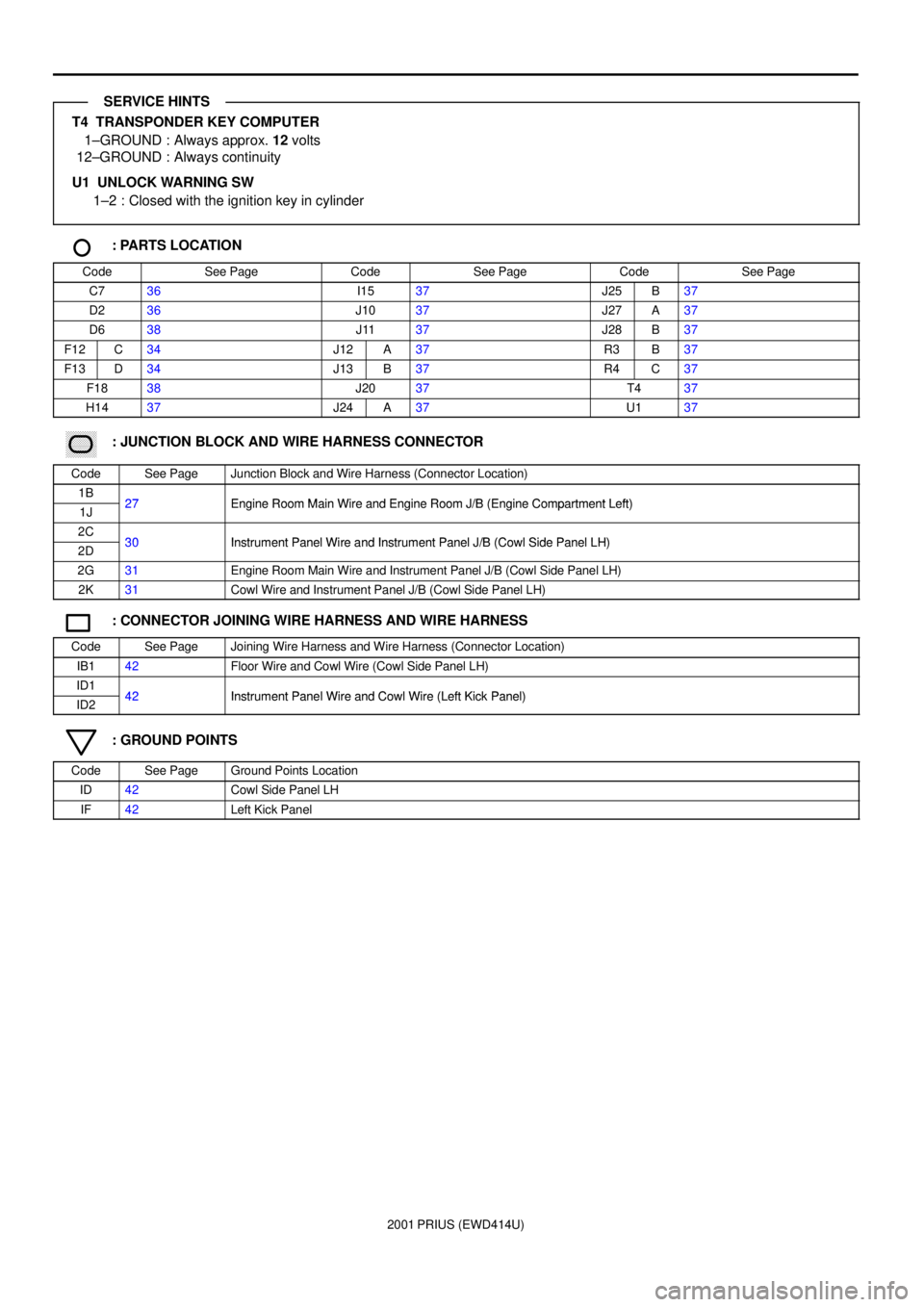
T4 TRANSPONDER KEY COMPUTER
1±GROUND : Always approx. 12 volts
12±GROUND : Always continuity
U1 UNLOCK WARNING SW
1±2 : Closed with the ignition key in cylinder
: PARTS LOCATION
CodeSee PageCodeSee PageCodeSee Page
C736I1537J25B37
D236J1037J27A37
D638J1137J28B37
F12C34J12A37R3B37
F13D34J13B37R4C37
F1838J2037T437
H1437J24A37U137
������ ���: JUNCTION BLOCK AND WIRE HARNESS CONNECTOR
CodeSee PageJunction Block and Wire Harness (Connector Location)
1B27Engine Room Main Wire and Engine Room J/B (Engine Compartment Left)1J27Engine Room Main Wire and Engine Room J/B (Engine Compartment Left)
2C30Instrument Panel Wire and Instrument Panel J/B (Cowl Side Panel LH)2D30Instrument Panel Wire and Instrument Panel J/B (Cowl Side Panel LH)
2G31Engine Room Main Wire and Instrument Panel J/B (Cowl Side Panel LH)
2K31Cowl Wire and Instrument Panel J/B (Cowl Side Panel LH)
: CONNECTOR JOINING WIRE HARNESS AND WIRE HARNESS
CodeSee PageJoining Wire Harness and Wire Harness (Connector Location)
IB142Floor Wire and Cowl Wire (Cowl Side Panel LH)
ID142Instrument Panel Wire and Cowl Wire (Left Kick Panel)ID242Instrument Panel Wire and Cowl Wire (Left Kick Panel)
: GROUND POINTS
CodeSee PageGround Points Location
ID42Cowl Side Panel LH
IF42Left Kick Panel
SERVICE HINTS
Page 78 of 1943
2001 PRIUS (EWD414U)
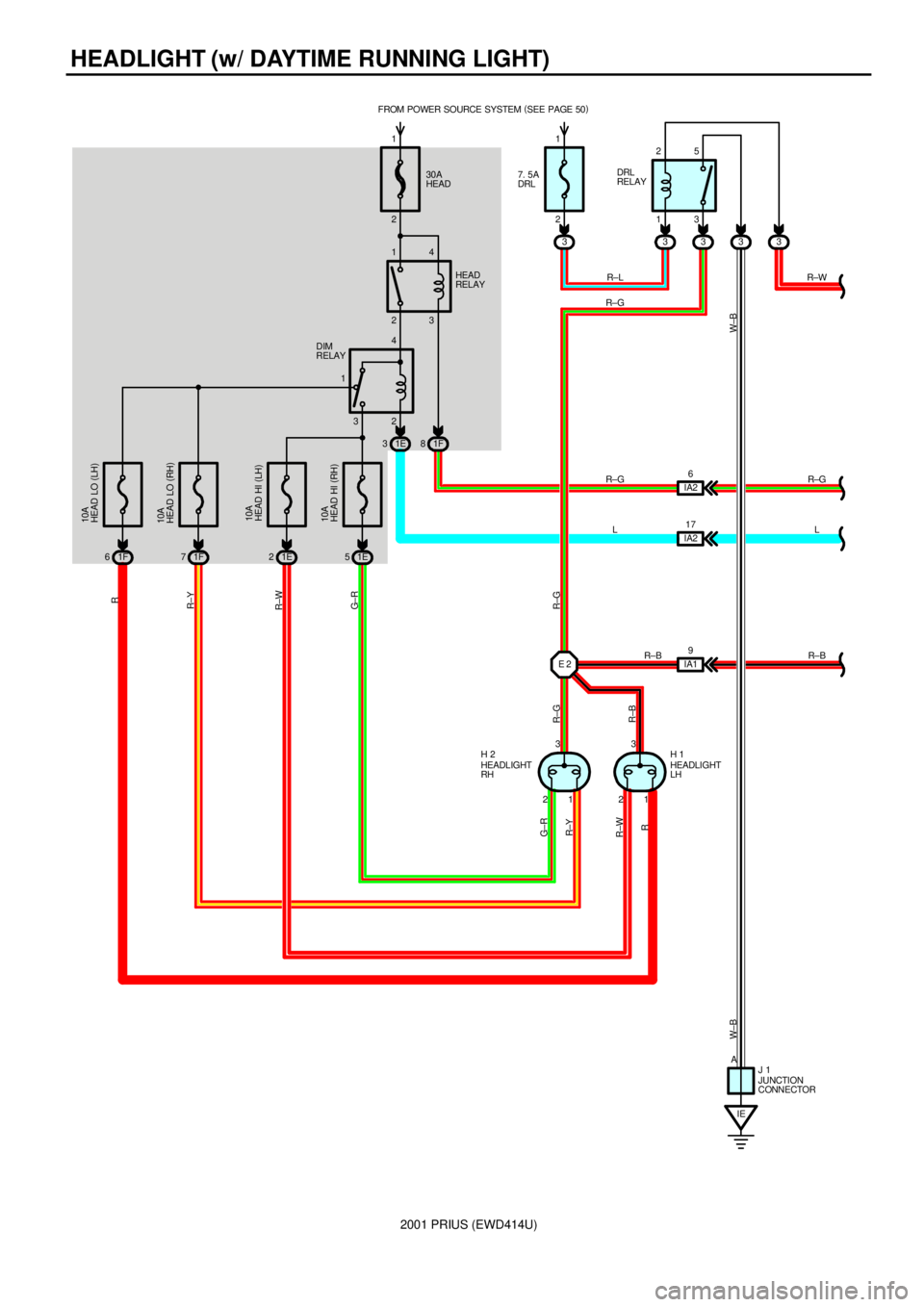
HEADLIGHT (w/ DAYTIME RUNNING LIGHT)
30A
HEAD FROM POWER SOURCE SYSTEM (
SEE PAGE 50)
23 14
32 14 2 1
10A
HEAD HI (
RH) 10A
HEAD HI (
LH) 10A
HEAD LO (
RH) 10A
HEAD LO (
LH)
213
213IA19 1E 5 1E 2 1F 7 1F 6313 25
33 7. 5A
DRL
33
IE 1E 31F8
IA217 IA26
JUNCTION
CONNECTOR J 1 A
G± R R±WR±YR
R±G R±G
R±W
R
W±B W±B
R±G
LR±G
L R±W
R±B R±L
R±G HEAD
RELAY
DIM
RELAYDRL
RELAY
R±B
HEADLIGHT
LH H 1
HEADLIGHT
RH H 2
R±Y G±R
2 1
E 2
R±B
Page 79 of 1943
2001 PRIUS (EWD414U)
2B 62A 7 10 2A72I
ID OFF
TAIL
HEAD
LOW
HIGH
IG ID2 510A
GAUGE FROM POWER SOURCE SYSTEM (
SEE PAGE 50)
2K 10
B E
A E
1ID2 7 7. 5A
ECU±B
2C 5
ID1 8
IA2 16
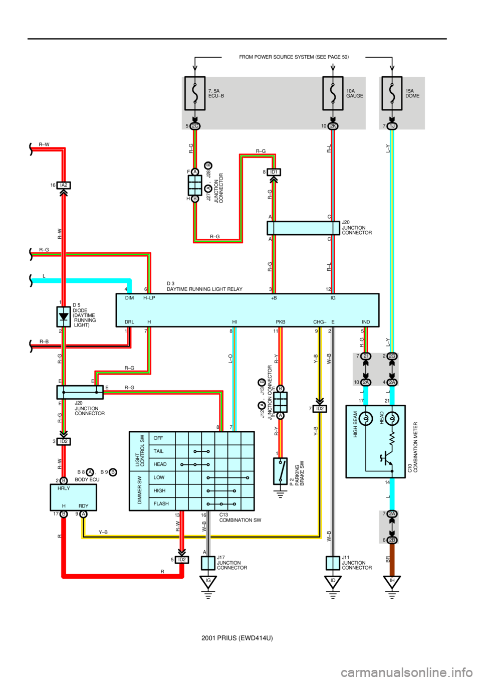
DAYTIME RUNNING LIGHT RELAY D 3
JUNCTION
CONNECTOR J20JUNCTION
CONNECTOR J2 0
JUNCTION
CONNECTOR J17
JUNCTION
CONNECTOR J1 1
PARKING
BRAKE SW P 2
COMBINATION SW C13 DIODE
(
DAYTIME
RUNNING
LIGHT) D 5 1
EE46 3 12AC
87
A17 2
E17 8 11 92 5AC
14
R±W
R±G
R±L R±G R±G
R±L R±W RR±GR±G
L±O
R±Y
Y±B
W±B
R±G L Y±B R±Y
BRW±B
L
R±BL R±G R±W
R R±G R±G
R±W
W±B
EDRL HDIM H±LP +B IG
HI PKB CHG± IND
ID2 3
13 16
JUNCTION CONNECTORB J12 A , J13
B 2
B 17 A9 BODY ECUB B 8 , B 9A
Y±BA F
B HR±G
R±G
JUNCTION
CONNECTORB J27 A , J28
E
FLASH
LIGHT
CONTROL SW DIMMER SW
15A
DOME
1J 7
HIGH BEAM
HEAD
42A 22G
LL±Y
21
COMBINATION METER C10L±Y
H RDY HRLY
IH
Page 80 of 1943
2001 PRIUS (EWD414U)
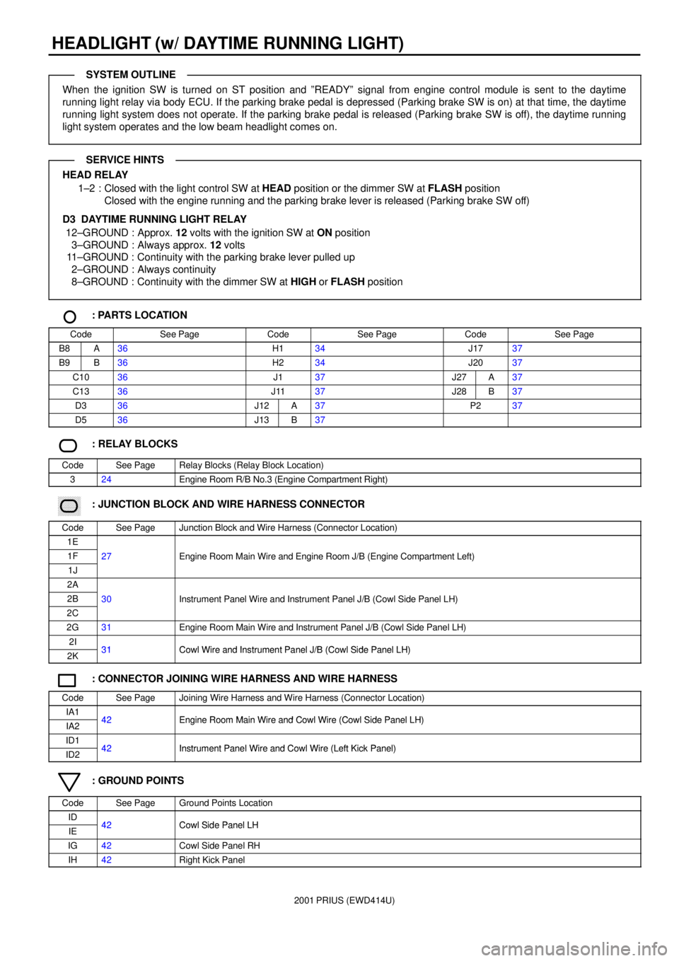
HEADLIGHT (w/ DAYTIME RUNNING LIGHT)
When the ignition SW is turned on ST position and ºREADYº signal from engine control module is sent to the daytime
running light relay via body ECU. If the parking brake pedal is depressed (Parking brake SW is on) at that time, the daytime
running light system does not operate. If the parking brake pedal is released (Parking brake SW is off), the daytime running
light system operates and the low beam headlight comes on.
HEAD RELAY
1±2 : Closed with the light control SW at HEAD position or the dimmer SW at FLASH position
Closed with the engine running and the parking brake lever is released (Parking brake SW off)
D3 DAYTIME RUNNING LIGHT RELAY
12±GROUND : Approx. 12 volts with the ignition SW at ON position
3±GROUND : Always approx. 12 volts
11±GROUND : Continuity with the parking brake lever pulled up
2±GROUND : Always continuity
8±GROUND : Continuity with the dimmer SW at HIGH or FLASH position
: PARTS LOCATION
CodeSee PageCodeSee PageCodeSee Page
B8A36H134J1737
B9B36H234J2037
C1036J137J27A37
C1336J1137J28B37
D336J12A37P237
D536J13B37
: RELAY BLOCKS
CodeSee PageRelay Blocks (Relay Block Location)
324Engine Room R/B No.3 (Engine Compartment Right)
������ ���: JUNCTION BLOCK AND WIRE HARNESS CONNECTOR
CodeSee PageJunction Block and Wire Harness (Connector Location)
1E
1F27Engine Room Main Wire and Engine Room J/B (Engine Compartment Left)
1J
gg(g)
2A
2B30Instrument Panel Wire and Instrument Panel J/B (Cowl Side Panel LH)
2C
()
2G31Engine Room Main Wire and Instrument Panel J/B (Cowl Side Panel LH)
2I31Cowl Wire and Instrument Panel J/B (Cowl Side Panel LH)2K31Cowl Wire and Instrument Panel J/B (Cowl Side Panel LH)
: CONNECTOR JOINING WIRE HARNESS AND WIRE HARNESS
CodeSee PageJoining Wire Harness and Wire Harness (Connector Location)
IA142Engine Room Main Wire and Cowl Wire (Cowl Side Panel LH)IA242Engine Room Main Wire and Cowl Wire (Cowl Side Panel LH)
ID142Instrument Panel Wire and Cowl Wire (Left Kick Panel)ID242Instrument Panel Wire and Cowl Wire (Left Kick Panel)
: GROUND POINTS
CodeSee PageGround Points Location
ID42Cowl Side Panel LHIE42Cowl Side Panel LH
IG42Cowl Side Panel RH
IH42Right Kick Panel
SYSTEM OUTLINE
SERVICE HINTS