low oil pressure TOYOTA RAV4 1996 Service User Guide
[x] Cancel search | Manufacturer: TOYOTA, Model Year: 1996, Model line: RAV4, Model: TOYOTA RAV4 1996Pages: 1632, PDF Size: 41.64 MB
Page 677 of 1632
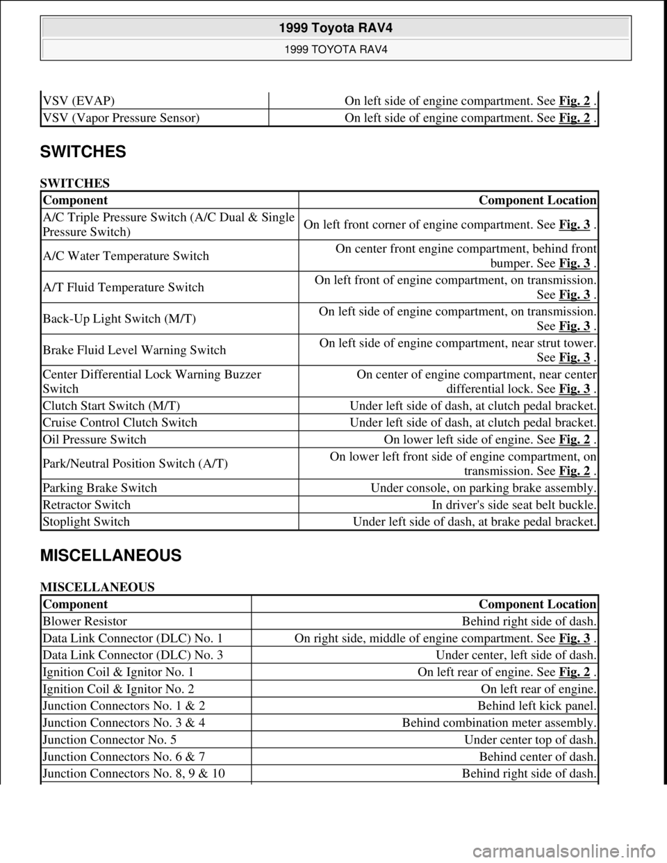
SWITCHES
SWITCHES
MISCELLANEOUS
MISCELLANEOUS
VSV (EVAP)On left side of engine compartment. See Fig. 2 .
VSV (Vapor Pressure Sensor)On left side of engine compartment. See Fig. 2 .
ComponentComponent Location
A/C Triple Pressure Switch (A/C Dual & Single
Pressure Switch)On left front corner of engine compartment. See Fig. 3 .
A/C Water Temperature SwitchOn center front engine compartment, behind front
bumper. See Fig. 3
.
A/T Fluid Temperature SwitchOn left front of engine compartment, on transmission.
See Fig. 3
.
Back-Up Light Switch (M/T)On left side of engine compartment, on transmission.
See Fig. 3
.
Brake Fluid Level Warning SwitchOn left side of engine compartment, near strut tower.
See Fig. 3
.
Center Differential Lock Warning Buzzer
SwitchOn center of engine compartment, near center
differential lock. See Fig. 3
.
Clutch Start Switch (M/T)Under left side of dash, at clutch pedal bracket.
Cruise Control Clutch SwitchUnder left side of dash, at clutch pedal bracket.
Oil Pressure SwitchOn lower left side of engine. See Fig. 2 .
Park/Neutral Position Switch (A/T)On lower left front side of engine compartment, on
transmission. See Fig. 2
.
Parking Brake SwitchUnder console, on parking brake assembly.
Retractor SwitchIn driver's side seat belt buckle.
Stoplight SwitchUnder left side of dash, at brake pedal bracket.
ComponentComponent Location
Blower ResistorBehind right side of dash.
Data Link Connector (DLC) No. 1On right side, middle of engine compartment. See Fig. 3 .
Data Link Connector (DLC) No. 3Under center, left side of dash.
Ignition Coil & Ignitor No. 1On left rear of engine. See Fig. 2 .
Ignition Coil & Ignitor No. 2On left rear of engine.
Junction Connectors No. 1 & 2Behind left kick panel.
Junction Connectors No. 3 & 4Behind combination meter assembly.
Junction Connector No. 5Under center top of dash.
Junction Connectors No. 6 & 7Behind center of dash.
Junction Connectors No. 8, 9 & 10Behind right side of dash.
1999 Toyota RAV4
1999 TOYOTA RAV4
Microsoft
Sunday, November 22, 2009 10:17:32 AMPage 4 © 2005 Mitchell Repair Information Company, LLC.
Page 693 of 1632
1. Remove driver-side rear seat and floor panel cover for access to fuel pump electrical connector.
2. Disconnect fuel pump electrical connector. Start engine and allow engine to idle until engine stalls. Turn
ignition off.
3. Reconnect fuel pump electrical connector. Reinstall floor panel cover and driver-side rear seat.
4. Disconnect negative battery cable. Place an approved gasoline container under fuel line. Cover fuel line
connection with shop towel.
5. Slowly loosen fuel line connection to release fuel pressure. Once fuel pressure is released, fuel system
components may be serviced.
ENGINE
Removal
1. Engine and transaxle are removed as an assembly from bottom of engine compartment. Release fuel
pressure. See FUEL PRESSURE RELEASE
. Remove hood, battery and battery tray. Drain cooling
system, and engine and transaxle oil.
2. Disconnect control cables at throttle body. Remove air cleaner assembly and air cleaner case. Remove
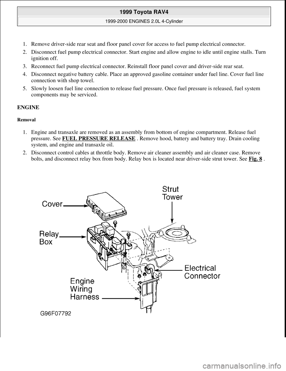
bolts, and disconnect relay box from body. Relay box is located near driver-side strut tower. See Fig. 8
.
1999 Toyota RAV4
1999-2000 ENGINES 2.0L 4-Cylinder
Microsoft
Sunday, November 22, 2009 10:22:26 AMPage 10 © 2005 Mitchell Repair Information Company, LLC.
Page 701 of 1632
Removal
1. Release fuel pressure. See FUEL PRESSURE RELEASE . Drain cooling system. Raise and support
vehicle. Remove right lower engine cover.
2. Disconnect control cables at throttle body. Remove air cleaner assembly and air cleaner case. Remove
accessory drive belt and generator.
3. Remove front exhaust pipe. Remove exhaust manifold and heat insulator assembly. Disconnect oxygen
sensor (except California) or Air/Fuel (A/F) ratio sensor (California), and remove exhaust manifold and
heat shield. Remove sensors from exhaust manifold and front catalytic converter, if equipped.
4. Remove heat insulator from front exhaust pipe. Remove throttle body and gasket. Remove ignition coils
with spark plug wires attached.
5. Disconnect necessary electrical connectors, coolant hoses and vacuum hoses from cylinder head and
intake manifold. Remove coolant outlet, coolant by-pass pipe and gaskets.
6. Disconnect hoses and ground strap. Remove union bolt, and disconnect fuel line at fuel filter. Remove
EGR valve and vacuum modulator. Disconnect power steering idle-up hoses from air tube.
7. Remove 2 bolts and accelerator cable bracket. Disconnect PCV hoses, cable brackets and control cables
for access to valve cover. Disconnect engine wiring harness protector at rear of timing belt cover for
access to valve cover. Remove nuts, grommets, valve cover and gasket. Note location of grommets for
reassembly reference, as grommets must be installed in original location.
8. Remove bolts, and disconnect engine wiring harness protector from left side of intake manifold.
Disconnect electrical connectors at injectors, A/C compressor and crankshaft position sensor. Remove
engine wiring harness clamps from timing belt cover and generator drive belt adjusting bar.
9. Remove scuff plate from passenger-side door opening and passenger-side kick panel. Remove right side
cowl side trim and floor carpet center cover. Disconnect 2 electrical connectors from Engine Control
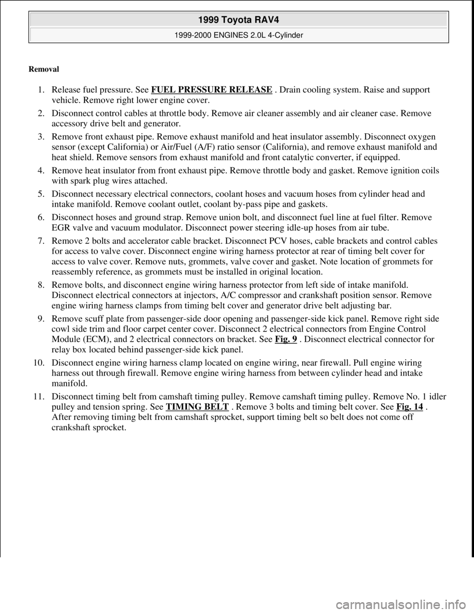
Module (ECM), and 2 electrical connectors on bracket. See Fig. 9
. Disconnect electrical connector for
relay box located behind passenger-side kick panel.
10. Disconnect engine wiring harness clamp located on engine wiring, near firewall. Pull engine wiring
harness out through firewall. Remove engine wiring harness from between cylinder head and intake
manifold.
11. Disconnect timing belt from camshaft timing pulley. Remove camshaft timing pulley. Remove No. 1 idler
pulley and tension spring. See TIMING BELT
. Remove 3 bolts and timing belt cover. See Fig. 14 .
After removing timing belt from camshaft sprocket, support timing belt so belt does not come off
crankshaft sprocket.
1999 Toyota RAV4
1999-2000 ENGINES 2.0L 4-Cylinder
Microsoft
Sunday, November 22, 2009 10:22:26 AMPage 18 © 2005 Mitchell Repair Information Company, LLC.
Page 705 of 1632
control cable to intake manifold. On all models, install NEW gasket and EGR valve with union nut and 2
nuts. Install vacuum modulator to clamp on intake manifold. Connect vacuum hoses to EGR VSV.
Connect fuel inlet hose to fuel filter
14. Connect vacuum sensor hose to gas filter, and brake booster vacuum hose to intake manifold. Install
throttle body. Install NEW "O" ring on coolant by-pass pipe, and NEW gasket on water pump cover
before installing coolant by-pass pipe. Apply soapy water solution to "O" ring before installing coolant
by-pass pipe. Install by-pass pipe.
15. Install NEW gasket and water outlet. Connect radiator, water by-pass and heater water hoses. Connect
ECT sensor and sender gauge connectors. Connect oil pressure switch.
16. Install ignition coils, manifold stay and spark plug wires. Connect wire clamp to manifold stay. Connect
spark plug wires to spark plugs and clamps on cylinder head cover. Connect ignition coil connectors.
17. Install 2 heat insulators. Install lower heat insulator. On California models, install A/F sensor to exhaust
manifold. All others, install oxygen sensor (bank 1 sensor 1) to exhaust manifold.
18. Using a new gasket, install exhaust manifold and heat insulator assembly. Install right-side exhaust
manifolds stay (California). Install left-side exhaust manifold stay. Install upper manifold heat insulator.
Connect A/F sensor connectors (California), or Oxygen sensor (bank 1 sensor 1).
19. Use NEW gasket and NEW nuts when installing front exhaust pipe. Ensure all bolts/nuts are loosely
installed on front exhaust pipe before tightening to specification. See TORQUE SPECIFICATIONS
20. Install generator and air cleaner and cap. Connect accelerator cable to throttle body and cable bracket. On
A/T models, connect throttle cable to throttle body and cable bracket. On all models, start engine and
check for leaks. Recheck engine coolant and oil level. Install right-side engine undercover.
CRANKSHAFT FRONT SEAL
Removal & Installation (Oil Pump Installed)
1. Remove timing belt and crankshaft sprocket. See TIMING BELT . Using a knife, cut lip from seal. Pry
seal from oil pump housing. DO NOT damage sealing surfaces.
2. To install, apply grease to lip of new seal. Using hammer and Seal Installer (SST 09226-10010), install
seal until seal surface is even with oil pump housing. To install remaining components, reverse removal
procedure.
Removal & Installation (Oil Pump Removed)
Using hammer and drift, remove seal from oil pump housing. To install, use hammer and Seal Installer (SST
09226-10010). Install seal until seal surface is even with oil pump housing. Apply grease to lip of new seal.
TIMING BELT
CAUTION: If reusing timing belt, mark direction of timing belt rotation, and place
reference mark on timing belt at camshaft sprocket for reassembly
reference. Also, place reference mark on timing belt at upper edge of No. 1
timing belt cover. DO NOT bend, twist or turn timing belt inside-out. DO
NOT expose timing to oil, water or steam.
1999 Toyota RAV4
1999-2000 ENGINES 2.0L 4-Cylinder
Microsoft
Sunday, November 22, 2009 10:22:26 AMPage 22 © 2005 Mitchell Repair Information Company, LLC.
Page 739 of 1632
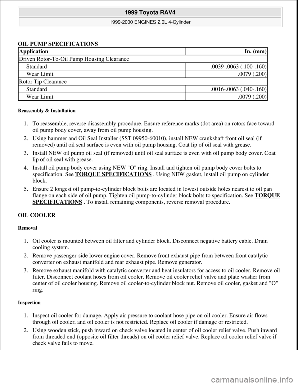
OIL PUMP SPECIFICATIONS
Reassembly & Installation
1. To reassemble, reverse disassembly procedure. Ensure reference marks (dot area) on rotors face toward
oil pump body cover, away from oil pump housing.
2. Using hammer and Oil Seal Installer (SST 09950-60010), install NEW crankshaft front oil seal (if
removed) until oil seal surface is even with oil pump housing. Coat lip of oil seal with grease.
3. Install NEW oil pump oil seal (if removed) until oil seal surface is even with oil pump body cover. Coat
lip of oil seal with grease.
4. Install oil pump body cover using NEW "O" ring. Install and tighten oil pump body cover bolts to
specification. See TORQUE SPECIFICATIONS
. Using NEW gasket, install oil pump on cylinder
block.
5. Ensure 2 longest oil pump-to-cylinder block bolts are located in lowest outside holes nearest to oil pan
flange on each side of oil pump. Tighten oil pump-to-cylinder block bolts to specification. See TORQUE
SPECIFICATIONS . To install remaining components, reverse removal procedure.
OIL COOLER
Removal
1. Oil cooler is mounted between oil filter and cylinder block. Disconnect negative battery cable. Drain
cooling system.
2. Remove passenger-side lower engine cover. Remove front exhaust pipe from between front catalytic
converter on exhaust manifold and rear exhaust pipe. Remove generator.
3. Remove exhaust manifold with catalytic converter and heat insulators for access to oil cooler. Remove oil
filter. Disconnect coolant hoses from oil cooler. Remove oil cooler relief valve and plate washer from
center of oil cooler housing. Remove oil cooler-to-cylinder block nut. Remove oil cooler, gasket and "O"
ring.
Inspection
1. Inspect oil cooler for damage. Apply air pressure to coolant hose pipe on oil cooler. Ensure air flows
through oil cooler, and oil cooler is not restricted. Replace oil cooler if damage or restricted.
2. Using wooden stick, push inward on check valve located in center of oil cooler relief valve. Push inward
from threaded end (opposite oil filter threads) on oil cooler relief valve. Replace oil cooler relief valve if
check valve fails to move.
ApplicationIn. (mm)
Driven Rotor-To-Oil Pump Housing Clearance
Standard.0039-.0063 (.100-.160)
Wear Limit.0079 (.200)
Rotor Tip Clearance
Standard.0016-.0063 (.040-.160)
Wear Limit.0079 (.200)
1999 Toyota RAV4
1999-2000 ENGINES 2.0L 4-Cylinder
Microsoft
Sunday, November 22, 2009 10:22:27 AMPage 56 © 2005 Mitchell Repair Information Company, LLC.
Page 758 of 1632
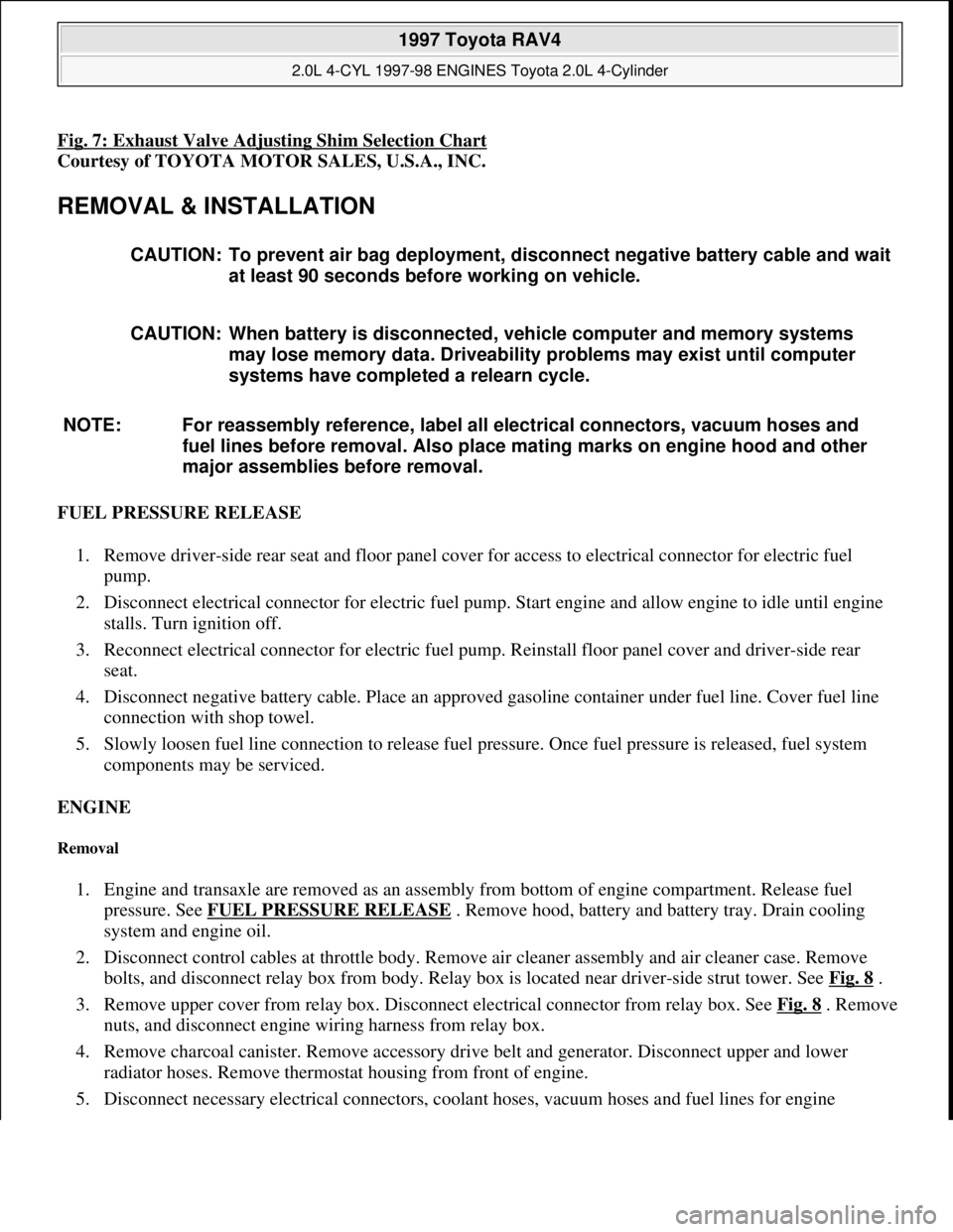
Fig. 7: Exhaust Valve Adjusting Shim Selection Chart
Courtesy of TOYOTA MOTOR SALES, U.S.A., INC.
REMOVAL & INSTALLATION
FUEL PRESSURE RELEASE
1. Remove driver-side rear seat and floor panel cover for access to electrical connector for electric fuel
pump.
2. Disconnect electrical connector for electric fuel pump. Start engine and allow engine to idle until engine
stalls. Turn ignition off.
3. Reconnect electrical connector for electric fuel pump. Reinstall floor panel cover and driver-side rear
seat.
4. Disconnect negative battery cable. Place an approved gasoline container under fuel line. Cover fuel line
connection with shop towel.
5. Slowly loosen fuel line connection to release fuel pressure. Once fuel pressure is released, fuel system
components may be serviced.
ENGINE
Removal
1. Engine and transaxle are removed as an assembly from bottom of engine compartment. Release fuel
pressure. See FUEL PRESSURE RELEASE
. Remove hood, battery and battery tray. Drain cooling
system and engine oil.
2. Disconnect control cables at throttle body. Remove air cleaner assembly and air cleaner case. Remove
bolts, and disconnect relay box from body. Relay box is located near driver-side strut tower. See Fig. 8
.
3. Remove upper cover from relay box. Disconnect electrical connector from relay box. See Fig. 8
. Remove
nuts, and disconnect engine wiring harness from relay box.
4. Remove charcoal canister. Remove accessory drive belt and generator. Disconnect upper and lower
radiator hoses. Remove thermostat housing from front of engine.
5. Disconnect necessar
y electrical connectors, coolant hoses, vacuum hoses and fuel lines for engine CAUTION: To prevent air bag deployment, disconnect negative battery cable and wait
at least 90 seconds before working on vehicle.
CAUTION: When battery is disconnected, vehicle computer and memory systems
may lose memory data. Driveability problems may exist until computer
systems have completed a relearn cycle.
NOTE: For reassembly reference, label all electrical connectors, vacuum hoses and
fuel lines before removal. Also place mating marks on engine hood and other
major assemblies before removal.
1997 Toyota RAV4
2.0L 4-CYL 1997-98 ENGINES Toyota 2.0L 4-Cylinder
Microsoft
Sunday, November 22, 2009 10:23:30 AMPage 10 © 2005 Mitchell Repair Information Company, LLC.
Page 765 of 1632
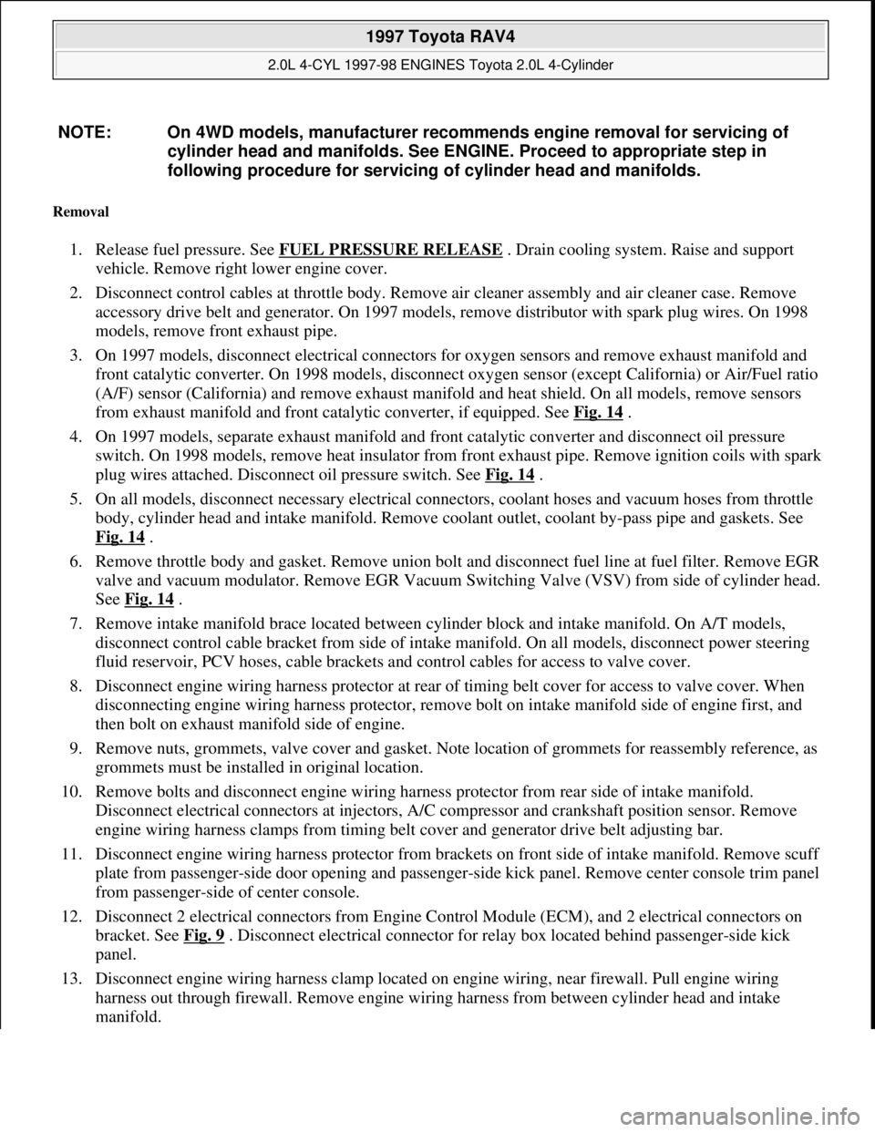
Removal
1. Release fuel pressure. See FUEL PRESSURE RELEASE . Drain cooling system. Raise and support
vehicle. Remove right lower engine cover.
2. Disconnect control cables at throttle body. Remove air cleaner assembly and air cleaner case. Remove
accessory drive belt and generator. On 1997 models, remove distributor with spark plug wires. On 1998
models, remove front exhaust pipe.
3. On 1997 models, disconnect electrical connectors for oxygen sensors and remove exhaust manifold and
front catalytic converter. On 1998 models, disconnect oxygen sensor (except California) or Air/Fuel ratio
(A/F) sensor (California) and remove exhaust manifold and heat shield. On all models, remove sensors
from exhaust manifold and front catalytic converter, if equipped. See Fig. 14
.
4. On 1997 models, separate exhaust manifold and front catalytic converter and disconnect oil pressure
switch. On 1998 models, remove heat insulator from front exhaust pipe. Remove ignition coils with spark
plug wires attached. Disconnect oil pressure switch. See Fig. 14
.
5. On all models, disconnect necessary electrical connectors, coolant hoses and vacuum hoses from throttle
body, cylinder head and intake manifold. Remove coolant outlet, coolant by-pass pipe and gaskets. See
Fig. 14
.
6. Remove throttle body and gasket. Remove union bolt and disconnect fuel line at fuel filter. Remove EGR
valve and vacuum modulator. Remove EGR Vacuum Switching Valve (VSV) from side of cylinder head.
See Fig. 14
.
7. Remove intake manifold brace located between cylinder block and intake manifold. On A/T models,
disconnect control cable bracket from side of intake manifold. On all models, disconnect power steering
fluid reservoir, PCV hoses, cable brackets and control cables for access to valve cover.
8. Disconnect engine wiring harness protector at rear of timing belt cover for access to valve cover. When
disconnecting engine wiring harness protector, remove bolt on intake manifold side of engine first, and
then bolt on exhaust manifold side of engine.
9. Remove nuts, grommets, valve cover and gasket. Note location of grommets for reassembly reference, as
grommets must be installed in original location.
10. Remove bolts and disconnect engine wiring harness protector from rear side of intake manifold.
Disconnect electrical connectors at injectors, A/C compressor and crankshaft position sensor. Remove
engine wiring harness clamps from timing belt cover and generator drive belt adjusting bar.
11. Disconnect engine wiring harness protector from brackets on front side of intake manifold. Remove scuff
plate from passenger-side door opening and passenger-side kick panel. Remove center console trim panel
from passenger-side of center console.
12. Disconnect 2 electrical connectors from Engine Control Module (ECM), and 2 electrical connectors on
bracket. See Fig. 9
. Disconnect electrical connector for relay box located behind passenger-side kick
panel.
13. Disconnect engine wiring harness clamp located on engine wiring, near firewall. Pull engine wiring
harness out through firewall. Remove engine wiring harness from between cylinder head and intake
manifold. NOTE: On 4WD models, manufacturer recommends engine removal for servicing of
cylinder head and manifolds. See ENGINE. Proceed to appropriate step in
following procedure for servicing of cylinder head and manifolds.
1997 Toyota RAV4
2.0L 4-CYL 1997-98 ENGINES Toyota 2.0L 4-Cylinder
Microsoft
Sunday, November 22, 2009 10:23:31 AMPage 17 © 2005 Mitchell Repair Information Company, LLC.
Page 807 of 1632
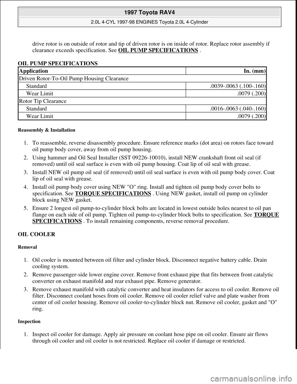
drive rotor is on outside of rotor and tip of driven rotor is on inside of rotor. Replace rotor assembly if
clearance exceeds specification. See OIL PUMP SPECIFICATIONS
.
OIL PUMP SPECIFICATIONS
Reassembly & Installation
1. To reassemble, reverse disassembly procedure. Ensure reference marks (dot area) on rotors face toward
oil pump body cover, away from oil pump housing.
2. Using hammer and Oil Seal Installer (SST 09226-10010), install NEW crankshaft front oil seal (if
removed) until oil seal surface is even with oil pump housing. Coat lip of oil seal with grease.
3. Install NEW oil pump oil seal (if removed) until oil seal surface is even with oil pump body cover. Coat
lip of oil seal with grease.
4. Install oil pump body cover using NEW "O" ring. Install and tighten oil pump body cover bolts to
specification. See TORQUE SPECIFICATIONS
. Using NEW gasket, install oil pump on cylinder
block using NEW gasket.
5. Ensure 2 longest oil pump-to-cylinder block bolts are located in lowest outside holes nearest to oil pan
flange on each side of oil pump. Tighten oil pump-to-cylinder block bolts to specification. See TORQUE
SPECIFICATIONS . To install remaining components, reverse removal procedure.
OIL COOLER
Removal
1. Oil cooler is mounted between oil filter and cylinder block. Disconnect negative battery cable. Drain
cooling system.
2. Remove passenger-side lower engine cover. Remove front exhaust pipe that fits between front catalytic
converter on exhaust manifold and rear exhaust pipe. Remove generator.
3. Remove exhaust manifold with catalytic converter and heat insulators for access to oil cooler. Remove oil
filter. Disconnect coolant hoses from oil cooler. Remove oil cooler relief valve and plate washer from
center of oil cooler housing. Remove oil cooler-to-cylinder block nut. Remove oil cooler, gasket and "O"
ring.
Inspection
1. Inspect oil cooler for damage. Apply air pressure on coolant hose pipe on oil cooler. Ensure air flows
through oil cooler and oil cooler is not restricted. Replace oil cooler if damage or restricted.
ApplicationIn. (mm)
Driven Rotor-To-Oil Pump Housing Clearance
Standard.0039-.0063 (.100-.160)
Wear Limit.0079 (.200)
Rotor Tip Clearance
Standard.0016-.0063 (.040-.160)
Wear Limit.0079 (.200)
1997 Toyota RAV4
2.0L 4-CYL 1997-98 ENGINES Toyota 2.0L 4-Cylinder
Microsoft
Sunday, November 22, 2009 10:23:31 AMPage 59 © 2005 Mitchell Repair Information Company, LLC.
Page 874 of 1632
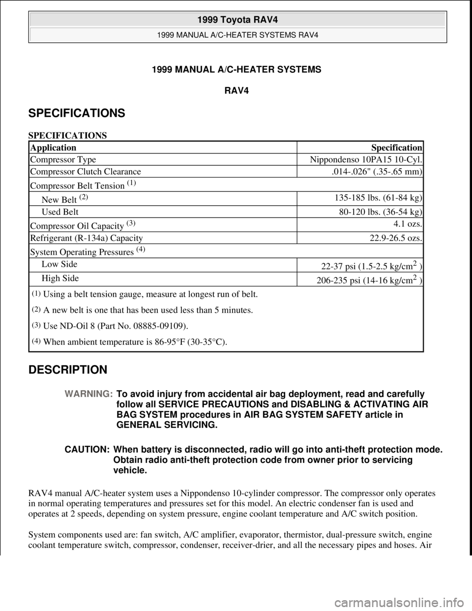
1999 MANUAL A/C-HEATER SYSTEMS
RAV4
SPECIFICATIONS
SPECIFICATIONS
DESCRIPTION
RAV4 manual A/C-heater system uses a Nippondenso 10-cylinder compressor. The compressor only operates
in normal operating temperatures and pressures set for this model. An electric condenser fan is used and
operates at 2 speeds, depending on system pressure, engine coolant temperature and A/C switch position.
System components used are: fan switch, A/C amplifier, evaporator, thermistor, dual-pressure switch, engine
coolant temperature switch, compressor, condenser, receive
r-drier, and all the necessary pipes and hoses. Air
ApplicationSpecification
Compressor TypeNippondenso 10PA15 10-Cyl.
Compressor Clutch Clearance.014-.026" (.35-.65 mm)
Compressor Belt Tension (1)
New Belt (2) 135-185 lbs. (61-84 kg)
Used Belt80-120 lbs. (36-54 kg)
Compressor Oil Capacity (3) 4.1 ozs.
Refrigerant (R-134a) Capacity22.9-26.5 ozs.
System Operating Pressures (4)
Low Side22-37 psi (1.5-2.5 kg/cm2 )
High Side206-235 psi (14-16 kg/cm2 )
(1)Using a belt tension gauge, measure at longest run of belt.
(2)A new belt is one that has been used less than 5 minutes.
(3)Use ND-Oil 8 (Part No. 08885-09109).
(4)When ambient temperature is 86-95°F (30-35°C).
WARNING:To avoid injury from accidental air bag deployment, read and carefully
follow all SERVICE PRECAUTIONS and DISABLING & ACTIVATING AIR
BAG SYSTEM procedures in AIR BAG SYSTEM SAFETY article in
GENERAL SERVICING.
CAUTION: When battery is disconnected, radio will go into anti-theft protection mode.
Obtain radio anti-theft protection code from owner prior to servicing
vehicle.
1999 Toyota RAV4
1999 MANUAL A/C-HEATER SYSTEMS RAV4
1999 Toyota RAV4
1999 MANUAL A/C-HEATER SYSTEMS RAV4
Microsoft
Sunday, November 22, 2009 10:29:27 AMPage 1 © 2005 Mitchell Repair Information Company, LLC.
Microsoft
Sunday, November 22, 2009 10:29:33 AMPage 1 © 2005 Mitchell Repair Information Company, LLC.
Page 882 of 1632
Courtesy of TOYOTA MOTOR SALES, U.S.A., INC.
IDLE AIR CONTROL (IAC) VALVE
Start engine and bring to normal operating temperature. Turn A/C switch on, set blower switch to high position
and adjust temperature control lever to maximum cooling. Ensure compressor clutch is engaged. Using
tachometer, ensure when compressor clutch engages, idle RPM increases 100-200 RPM and decreases a similar
amount when clutch is disengaged. If idle does not react as specified, check IAC valve and air intake system.
COMPRESSOR CLUTCH & COMPRESSOR LOCK SENSOR
Inspect pressure plate and rotor for signs of oil contamination. Check clutch bearing for noisy operation and
grease leakage. Check compressor lock sensor resistance. Disconnect compressor clutch/lock sensor 3-pin
connector. Measure resistance between terminals No. 1 (White wire) and No. 2 (Blue wire). Resistance should
be 65-125 ohms at 68°F (20°C). Replace as necessary. Check magnetic clutch operation. Apply battery voltage
to compressor clutch connector terminal No. 3 (Black wire). Connect negative battery lead to ground. Ensure
compressor clutch is energized. If compressor clutch is not energized, replace compressor clutch.
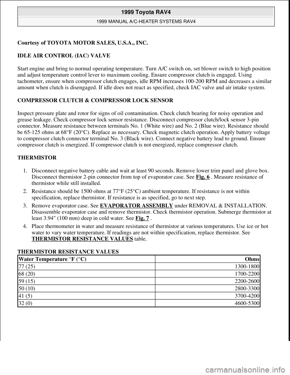
THERMISTOR
1. Disconnect negative battery cable and wait at least 90 seconds. Remove lower trim panel and glove box.
Disconnect thermistor 2-pin connector from top of evaporator case. See Fig. 6
. Measure resistance of
thermistor while still installed.
2. Resistance should be 1500 ohms at 77°F (25°C) ambient temperature. If resistance is not within
specification, replace thermistor. If resistance is as specified, go to next step.
3. Remove evaporator case. See EVAPORATOR ASSEMBLY
under REMOVAL & INSTALLATION.
Disassemble evaporator case and remove thermistor. Check thermistor operation. Submerge thermistor at
least 3.94" (100 mm) deep in cold water. See Fig. 7
.
4. Place thermometer in water and measure resistance of thermistor at various temperatures. Use ice or hot
water to vary water temperature. If readings are not within specification, replace thermistor. See
THERMISTOR RESISTANCE VALUES
table.
THERMISTOR RESISTANCE VALUES
Water Temperature °F (°C)Ohms
77 (25)1300-1800
68 (20)1700-2200
59 (15)2200-2600
50 (10)2800-3300
41 (5)3700-4200
32 (0)4600-5300
1999 Toyota RAV4
1999 MANUAL A/C-HEATER SYSTEMS RAV4
Microsoft
Sunday, November 22, 2009 10:29:28 AMPage 9 © 2005 Mitchell Repair Information Company, LLC.