oil pressure TOYOTA RAV4 1996 Service User Guide
[x] Cancel search | Manufacturer: TOYOTA, Model Year: 1996, Model line: RAV4, Model: TOYOTA RAV4 1996Pages: 1632, PDF Size: 41.64 MB
Page 457 of 1632
clutch hub (rotor). Remove snap ring and clutch coil.
3. Using an awl, remove bearing cover and retainer. Using Bearing Remover (MB991456), engage bearing
grooves. Place base of bearing remover over remover arms and tighten nut.
4. Tighten bearing remover bolt to withdraw bearing from compressor. Engage grooves of Shaft Seal
Remover/Installer (MB991458) and pull straight up on shaft seal.
Installation
1. To install shaft seal, ensure front housing is free of foreign objects. Lubricate Shaft Seal Protector
(MB991459) and place over compressor shaft. Lubricate shaft seal and install using shaft seal
remover/installer. Remove shaft seal protector.
2. Using a 21-mm socket or Drift (MB991301), carefully press bearing onto compressor shaft. Install clutch
coil so that alignment pin is engaged. Install clutch coil snap ring with tapered side facing out.
3. Align armature plate with crankshaft spline. Tighten shaft nut to 12 ft. lbs. (16 N.m). Using feeler gauge,
ensure air gap between pressure plate and pulley is 0.02-0.03" (0.5-0.8 mm) on Diamante and 0.016-
0.024" (0.4-0.6 mm) on all other models. If air
gap is incorrect, add or remove shim(s) as necessary.
1999 Toyota RAV4
1999 GENERAL SERVICING Compressor Servicing
Microsoft
Sunday, November 22, 2009 10:31:50 AMPage 20 © 2005 Mitchell Repair Information Company, LLC.
Page 459 of 1632
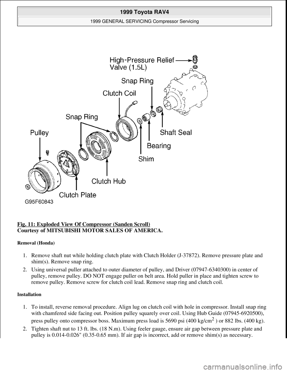
Fig. 11: Exploded View Of Compressor (Sanden Scroll)
Courtesy of MITSUBISHI MOTOR SALES OF AMERICA.
Removal (Honda)
1. Remove shaft nut while holding clutch plate with Clutch Holder (J-37872). Remove pressure plate and
shim(s). Remove snap ring.
2. Using universal puller attached to outer diameter of pulley, and Driver (07947-6340300) in center of
pulley, remove pulley. DO NOT engage puller on belt area. Hold puller in place and tighten screw to
remove pulley. Remove screw for clutch coil lead. Remove snap ring and clutch coil.
Installation
1. To install, reverse removal procedure. Align lug on clutch coil with hole in compressor. Install snap ring
with chamfered side facing out. Position pulley squarely over coil. Using Hub Guide (07945-6920500),
press pulley onto compressor boss. Maximum press load is 5690 psi (400 kg/cm
2 ) or 882 lbs. (400 kg).
2. Tighten shaft nut to 13 ft. lbs. (18 N.m). Using feeler gauge, ensure air gap between pressure plate and
pulle
y is 0.014-0.026" (0.35-0.65 mm). If air gap is incorrect, add or remove shim(s) as necessary.
1999 Toyota RAV4
1999 GENERAL SERVICING Compressor Servicing
Microsoft
Sunday, November 22, 2009 10:31:50 AMPage 22 © 2005 Mitchell Repair Information Company, LLC.
Page 460 of 1632
Removal (Mazda)
1. Remove compressor shaft nut while holding clutch plate with Clutch Holder (49-B061-010). Remove
clutch pressure plate and shim(s). If clutch pressure plate cannot be removed by hand, use Pressure Plate
Remover (49-B061-013).
2. Remove pulley assembly snap ring. Install a 2-jaw puller to outer diameter of pulley and a 1.0" (25 mm)
socket to compressor boss, and remove pulley. DO NOT engage puller on belt area. Hold puller in place
and tighten screw to remove pulley. Remove clutch coil snap ring and clutch coil.
Installation
1. To install, reverse removal procedure. Align lug on clutch coil with hole in compressor. Install snap ring
with chamfered side facing out. Position pulley squarely over coil. Ensure compressor boss and inside
area of pulley bearing are clean and free of foreign material. Using Pulley Installer (49-G032-311), press
pulley onto compressor boss.
2. Tighten compressor shaft nut to 14 ft. lbs. (19 N.m). Using feeler gauge, ensure air gap between clutch
pressure plate and pulley is 0.014-0.025" (0.35-0.65 mm). If air gap is incorrect, add or remove shim(s) as
necessary.
SANDEN 7-CYLINDER
CLUTCH COIL & BEARING
Removal (Jaguar)
1. Using 3 bolts, attach Puller (JD166-1) to clutch plate. While holding clutch plate with puller, remove
shaft nut. Install puller bolt in center of puller, and tighten bolt to remove clutch plate.
2. Remove adjustment shim(s) and Woodruff key. Remove pulley snap ring. Install threaded Adapter
(JD166-5), onto compressor shaft. Engage Collets (JD166-5) to inner diameter of pulley and attach Puller
(JD166-1) to collets.
3. Install puller bolt in center of puller, and tighten bolt to remove pulley. Press bearing out of drive belt
pulley. Remove screw for clutch coil lead. Remove snap ring and clutch coil.
Installation
To install clutch coil and bearing, reverse removal procedure. Tighten shaft nut. Ensure air gap is 0.016-
0.031" (0.40-0.80 mm). If air gap is incorrect, add or remove shim(s) as necessary.
Removal (Volkswagen)
1. Remove compressor shaft nut while holding clutch plate with two 1/4" (6 mm) bolts and Spanner Wrench
(Mastercool 90901). Remove clutch plate using two 1/4" (6 mm) bolts and Puller (Mastercool 90902).
Remove pulley assembly lock ring. See Fig. 12
. Using a 2-jaw puller, remove pulley assembly. Position
puller
jaws onto edge of pulley to prevent pulley groove from being deformed. NOTE: If shaft seal leaks, replace compressor.
1999 Toyota RAV4
1999 GENERAL SERVICING Compressor Servicing
Microsoft
Sunday, November 22, 2009 10:31:50 AMPage 23 © 2005 Mitchell Repair Information Company, LLC.
Page 463 of 1632
Installation
1. Using refrigerant oil, lubricate Shaft Seal Protector (09990-58240) and install over compressor shaft.
Using refrigerant oil, lubricate shaft seal lips and outer "O" ring. Install shaft seal over protector with "O"
ring toward compressor. Ensure lips of shaft seal point toward compressor.
2. Using Seal Remover/Installer (09990-48230) and hand pressure, slowly install shaft seal until upper face
of seal is lower than snap ring groove. Install snap ring with chamfered side facing compressor. Install
shaft key and felt ring. To complete installation, reverse removal procedure.
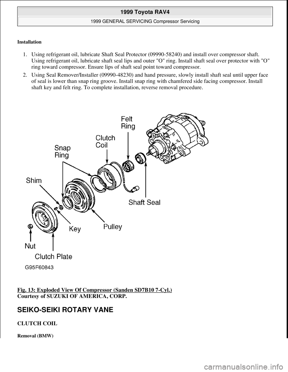
Fig. 13: Exploded View Of Compressor (Sanden SD7B10 7
-Cyl.)
Courtesy of SUZUKI OF AMERICA, CORP.
SEIKO-SEIKI ROTARY VANE
CLUTCH COIL
Removal (BMW)
1999 Toyota RAV4
1999 GENERAL SERVICING Compressor Servicing
Microsoft
Sunday, November 22, 2009 10:31:50 AMPage 26 © 2005 Mitchell Repair Information Company, LLC.
Page 465 of 1632
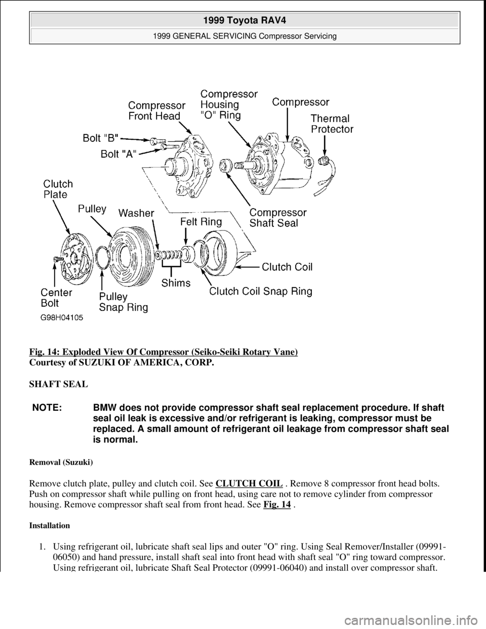
Fig. 14: Exploded View Of Compressor (Seiko-Seiki Rotary Vane)
Courtesy of SUZUKI OF AMERICA, CORP.
SHAFT SEAL
Removal (Suzuki)
Remove clutch plate, pulley and clutch coil. See CLUTCH COIL . Remove 8 compressor front head bolts.
Push on compressor shaft while pulling on front head, using care not to remove cylinder from compressor
housing. Remove compressor shaft seal from front head. See Fig. 14
.
Installation
1. Using refrigerant oil, lubricate shaft seal lips and outer "O" ring. Using Seal Remover/Installer (09991-
06050) and hand pressure, install shaft seal into front head with shaft seal "O" ring toward compressor.
Usin
g refrigerant oil, lubricate Shaft Seal Protector (09991-06040) and install over compressor shaft.
NOTE: BMW does not provide compressor shaft seal replacement procedure. If shaft
seal oil leak is excessive and/or refrigerant is leaking, compressor must be
replaced. A small amount of refrigerant oil leakage from compressor shaft seal
is normal.
1999 Toyota RAV4
1999 GENERAL SERVICING Compressor Servicing
Microsoft
Sunday, November 22, 2009 10:31:50 AMPage 28 © 2005 Mitchell Repair Information Company, LLC.
Page 677 of 1632
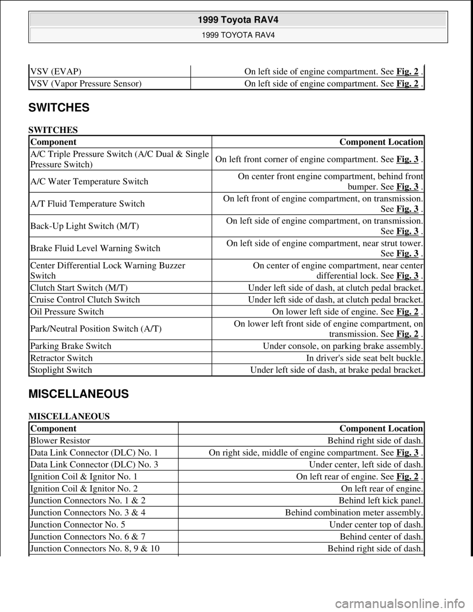
SWITCHES
SWITCHES
MISCELLANEOUS
MISCELLANEOUS
VSV (EVAP)On left side of engine compartment. See Fig. 2 .
VSV (Vapor Pressure Sensor)On left side of engine compartment. See Fig. 2 .
ComponentComponent Location
A/C Triple Pressure Switch (A/C Dual & Single
Pressure Switch)On left front corner of engine compartment. See Fig. 3 .
A/C Water Temperature SwitchOn center front engine compartment, behind front
bumper. See Fig. 3
.
A/T Fluid Temperature SwitchOn left front of engine compartment, on transmission.
See Fig. 3
.
Back-Up Light Switch (M/T)On left side of engine compartment, on transmission.
See Fig. 3
.
Brake Fluid Level Warning SwitchOn left side of engine compartment, near strut tower.
See Fig. 3
.
Center Differential Lock Warning Buzzer
SwitchOn center of engine compartment, near center
differential lock. See Fig. 3
.
Clutch Start Switch (M/T)Under left side of dash, at clutch pedal bracket.
Cruise Control Clutch SwitchUnder left side of dash, at clutch pedal bracket.
Oil Pressure SwitchOn lower left side of engine. See Fig. 2 .
Park/Neutral Position Switch (A/T)On lower left front side of engine compartment, on
transmission. See Fig. 2
.
Parking Brake SwitchUnder console, on parking brake assembly.
Retractor SwitchIn driver's side seat belt buckle.
Stoplight SwitchUnder left side of dash, at brake pedal bracket.
ComponentComponent Location
Blower ResistorBehind right side of dash.
Data Link Connector (DLC) No. 1On right side, middle of engine compartment. See Fig. 3 .
Data Link Connector (DLC) No. 3Under center, left side of dash.
Ignition Coil & Ignitor No. 1On left rear of engine. See Fig. 2 .
Ignition Coil & Ignitor No. 2On left rear of engine.
Junction Connectors No. 1 & 2Behind left kick panel.
Junction Connectors No. 3 & 4Behind combination meter assembly.
Junction Connector No. 5Under center top of dash.
Junction Connectors No. 6 & 7Behind center of dash.
Junction Connectors No. 8, 9 & 10Behind right side of dash.
1999 Toyota RAV4
1999 TOYOTA RAV4
Microsoft
Sunday, November 22, 2009 10:17:32 AMPage 4 © 2005 Mitchell Repair Information Company, LLC.
Page 693 of 1632
1. Remove driver-side rear seat and floor panel cover for access to fuel pump electrical connector.
2. Disconnect fuel pump electrical connector. Start engine and allow engine to idle until engine stalls. Turn
ignition off.
3. Reconnect fuel pump electrical connector. Reinstall floor panel cover and driver-side rear seat.
4. Disconnect negative battery cable. Place an approved gasoline container under fuel line. Cover fuel line
connection with shop towel.
5. Slowly loosen fuel line connection to release fuel pressure. Once fuel pressure is released, fuel system
components may be serviced.
ENGINE
Removal
1. Engine and transaxle are removed as an assembly from bottom of engine compartment. Release fuel
pressure. See FUEL PRESSURE RELEASE
. Remove hood, battery and battery tray. Drain cooling
system, and engine and transaxle oil.
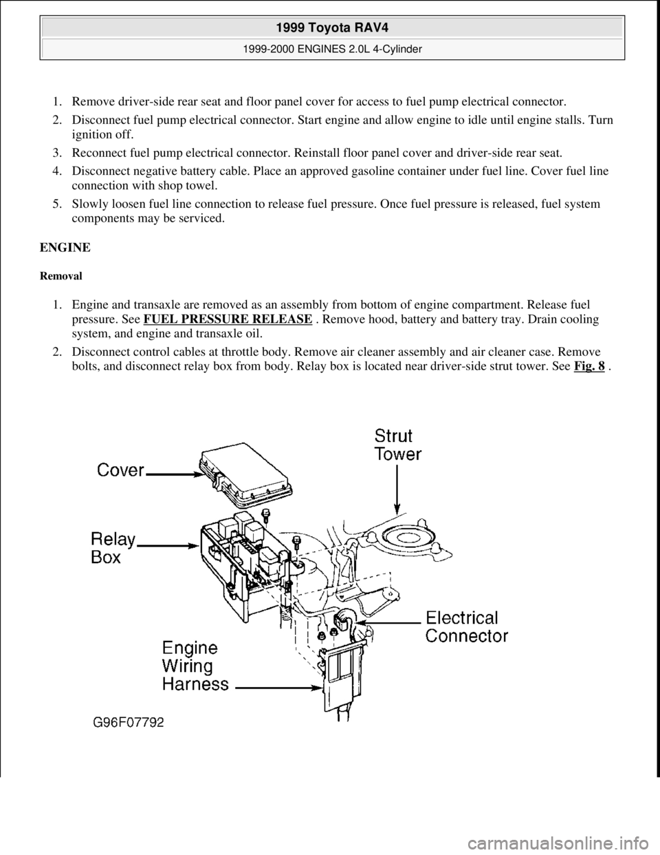
2. Disconnect control cables at throttle body. Remove air cleaner assembly and air cleaner case. Remove
bolts, and disconnect relay box from body. Relay box is located near driver-side strut tower. See Fig. 8
.
1999 Toyota RAV4
1999-2000 ENGINES 2.0L 4-Cylinder
Microsoft
Sunday, November 22, 2009 10:22:26 AMPage 10 © 2005 Mitchell Repair Information Company, LLC.
Page 701 of 1632
Removal
1. Release fuel pressure. See FUEL PRESSURE RELEASE . Drain cooling system. Raise and support
vehicle. Remove right lower engine cover.
2. Disconnect control cables at throttle body. Remove air cleaner assembly and air cleaner case. Remove
accessory drive belt and generator.
3. Remove front exhaust pipe. Remove exhaust manifold and heat insulator assembly. Disconnect oxygen
sensor (except California) or Air/Fuel (A/F) ratio sensor (California), and remove exhaust manifold and
heat shield. Remove sensors from exhaust manifold and front catalytic converter, if equipped.
4. Remove heat insulator from front exhaust pipe. Remove throttle body and gasket. Remove ignition coils
with spark plug wires attached.
5. Disconnect necessary electrical connectors, coolant hoses and vacuum hoses from cylinder head and
intake manifold. Remove coolant outlet, coolant by-pass pipe and gaskets.
6. Disconnect hoses and ground strap. Remove union bolt, and disconnect fuel line at fuel filter. Remove
EGR valve and vacuum modulator. Disconnect power steering idle-up hoses from air tube.
7. Remove 2 bolts and accelerator cable bracket. Disconnect PCV hoses, cable brackets and control cables
for access to valve cover. Disconnect engine wiring harness protector at rear of timing belt cover for
access to valve cover. Remove nuts, grommets, valve cover and gasket. Note location of grommets for
reassembly reference, as grommets must be installed in original location.
8. Remove bolts, and disconnect engine wiring harness protector from left side of intake manifold.
Disconnect electrical connectors at injectors, A/C compressor and crankshaft position sensor. Remove
engine wiring harness clamps from timing belt cover and generator drive belt adjusting bar.
9. Remove scuff plate from passenger-side door opening and passenger-side kick panel. Remove right side
cowl side trim and floor carpet center cover. Disconnect 2 electrical connectors from Engine Control
Module (ECM), and 2 electrical connectors on bracket. See Fig. 9
. Disconnect electrical connector for
relay box located behind passenger-side kick panel.
10. Disconnect engine wiring harness clamp located on engine wiring, near firewall. Pull engine wiring
harness out through firewall. Remove engine wiring harness from between cylinder head and intake
manifold.
11. Disconnect timing belt from camshaft timing pulley. Remove camshaft timing pulley. Remove No. 1 idler
pulley and tension spring. See TIMING BELT
. Remove 3 bolts and timing belt cover. See Fig. 14 .
After removing timing belt from camshaft sprocket, support timing belt so belt does not come off
crankshaft sprocket.
1999 Toyota RAV4
1999-2000 ENGINES 2.0L 4-Cylinder
Microsoft
Sunday, November 22, 2009 10:22:26 AMPage 18 © 2005 Mitchell Repair Information Company, LLC.
Page 703 of 1632
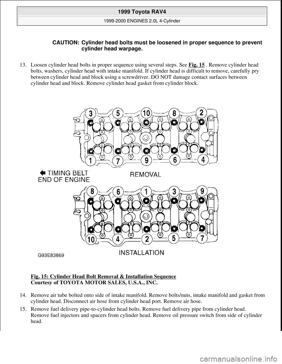
13. Loosen cylinder head bolts in proper sequence using several steps. See Fig. 15 . Remove cylinder head
bolts, washers, cylinder head with intake manifold. If cylinder head is difficult to remove, carefully pry
between cylinder head and block using a screwdriver. DO NOT damage contact surfaces between
cylinder head and block. Remove cylinder head gasket from cylinder block.
Fig. 15: Cylinder Head Bolt Removal & Installation Sequence
Courtesy of TOYOTA MOTOR SALES, U.S.A., INC.
14. Remove air tube bolted onto side of intake manifold. Remove bolts/nuts, intake manifold and gasket from
cylinder head. Disconnect air hose from cylinder head port. Remove air hose.
15. Remove fuel delivery pipe-to-cylinder head bolts. Remove fuel delivery pipe from cylinder head.
Remove fuel injectors and spacers from cylinder head. Remove oil pressure switch from side of cylinder
head. CAUTION: Cylinder head bolts must be loosened in proper sequence to prevent
cylinder head warpage.
1999 Toyota RAV4
1999-2000 ENGINES 2.0L 4-Cylinder
Microsoft
Sunday, November 22, 2009 10:22:26 AMPage 20 © 2005 Mitchell Repair Information Company, LLC.
Page 704 of 1632
Inspection
1. Inspect cylinder head warpage at cylinder block, exhaust manifold and intake manifold surfaces. Replace
cylinder head if warpage exceeds specification. See CYLINDER HEAD
table under ENGINE
SPECIFICATIONS.
2. Inspect cylinder block deck surface for warpage. Replace cylinder block if deck surface warpage exceeds
specification. See CYLINDER BLOCK
table under ENGINE SPECIFICATIONS.
3. Inspect intake and exhaust manifold machined surfaces for warpage. Replace component if warpage
exceeds .0118" (.300 mm). Inspect camshaft and components. See CAMSHAFT
.
4. Measure valve lifter diameter and bore diameter. Ensure oil clearance is within specification. Replace
components if not within specification. See VALVE LIFTERS
table under ENGINE
SPECIFICATIONS.
Installation
1. Apply adhesive to 2 or 3 threads of oil pressure switch, and install switch. Install NEW insulator at
bottom of fuel injector and NEW grommet on top of fuel injector. Coat NEW "O" rings with gasoline and
install on fuel injector.
2. Install 2 spacers on cylinder head. Install fuel injectors on cylinder head. Install fuel delivery pipe on fuel
injectors. Using twisting motion, push fuel injectors into fuel delivery pipe.
3. Install and slightly tighten fuel delivery pipe-to-cylinder head bolts. Ensure all fuel injectors rotate
smoothly. If fuel injector fails to rotate smoothly, check for improperly installed or damaged "O" rings.
4. Position electrical connector on fuel injector facing toward top of engine. Tighten fuel delivery pipe-to-
cylinder head bolts to specification. See TORQUE SPECIFICATIONS
.
5. Using NEW gasket, install intake manifold. Install and tighten bolts/nuts to specification. See TORQUE
SPECIFICATIONS . Install air tube on side of intake manifold.
6. Install adjusting shims and valve lifters in original location on cylinder head (if removed). Ensure valve
lifters rotate smoothly in cylinder head.
7. Install NEW gasket for cylinder head on cylinder block. Ensure all holes in gasket align with holes in
cylinder block.
8. Install cylinder head. Coat threads and bolt-to-cylinder contact surfaces on cylinder head bolts with
engine oil. Install and tighten cylinder head bolts in several steps, to specification in sequence. See Fig.
15 . See TORQUE SPECIFICATIONS .
9. If removed, install spark plug tubes. Install camshafts using proper procedure. See CAMSHAFT
. Install
No. 3 timing belt cover. Install and tighten bolts to specification. See TORQUE SPECIFICATIONS
.
10. To install remaining components, reverse removal procedure. If camshaft or cylinder head components
are serviced, adjust valve clearance. See VALVE CLEARANCE ADJUSTMENT
under
ADJUSTMENTS.
11. Before installing gasket and valve cover, apply sealant at front and rear valve cover areas on cylinder
head. See Fig. 6
. Using NEW gasket, install valve cover.
12. Install grommets in original location with marking on grommet aligned in designated area. See Fig. 7
.
Install and tighten valve cover nuts to specification. See TORQUE SPECIFICATIONS
.
13. Install VSV for EGR. Connect ground cable to intake manifold with bolt. Connect knock sensor
connector. Connect power steerin
g idle-up air hoses to air tube. On A/T models, connect A/T throttle
1999 Toyota RAV4
1999-2000 ENGINES 2.0L 4-Cylinder
Microsoft
Sunday, November 22, 2009 10:22:26 AMPage 21 © 2005 Mitchell Repair Information Company, LLC.