cruise control TOYOTA RAV4 1996 Service Repair Manual
[x] Cancel search | Manufacturer: TOYOTA, Model Year: 1996, Model line: RAV4, Model: TOYOTA RAV4 1996Pages: 1632, PDF Size: 41.64 MB
Page 17 of 1632
DTC Detecting Condition
Detection of the following condition may set DTC 41:
At vehicle speed of about 2 MPH or more, if voltage at ABS ECU terminal IG1 is less than 9.5 volts for
10 seconds or more, DTC 41 may set.
Diagnostic Procedure
1. Check charging system voltage. If voltage is 10-14 volts, system is okay. Go to next step. If voltage is not
10-14 volts, repair charging system. Ensure system fuses are okay.
2. Turn ignition off. Remove ABS ECU. Do not disconnect electrical connectors. Turn ignition switch to
ON position. Measure voltage between terminals IG1 and GND at ABS ECU harness connector. See Fig.
3 . If voltage is 10-14 volts, turn ignition off. Condition may be intermittent. Check ABS ECU connectors
for poor connection or damage. Repair as necessary. If connectors are okay, replace ABS ECU. If voltage
is not as specified, go to next step.
3. Measure resistance between ground and GND terminals at ABS ECU harness connector. See Fig. 3
. If
resistance is one ohm or less, go to next step. If resistance is more than one ohm, repair ground circuit
wiring. See WIRING DIAGRAMS
.
4. Remove ECU-IG fuse from instrument panel junction block. If fuse is blown, check for short circuit in all
wiring harnesses and components connected to ECU-IG fuse (ECM, A/C, cruise control, deceleration
sensor, combination meter, sun roof, shift lock, transmission pattern select switch). See WIRING
DIAGRAMS . Repair as necessary. If fuse is not blown, check for open circuit in wiring harness between
battery and ABS ECU. Repair as necessary.
DTC 43 & DTC 45: DECELERATION SENSOR MALFUNCTION (4WD MODELS ONLY)
DTC Detecting Conditions
Detection of the following conditions may set DTCs 43 or 45:
On 2-door models, if output voltage from deceleration sensor does not change for 16 consecutive times or
more when vehicle speed is decreased from 19 MPH to zero MPH, DTC 43 will set.
On 4-door models, after battery cables are connected, if input from deceleration sensor does not change at
one cycle (zero MPH to 19 MPH or more, then back to zero) for 16 consecutive times, DTC 43 will set.
When brake pedal is not depressed at vehicle speed of 3 MPH or more, and forward and backward force
(force of more than 0.4 "G") is detected for 30 seconds or more, DTC 43 will set.
On 2-door models, at vehicle speed of 19 MPH or more, if deceleration sensor output and vehicle
acceleration from wheel speed remains abnormally different for one minute or more, DTC 45 will set.
Diagnostic Procedure
1. Check deceleration sensor. See DECELERATION SENSOR CHECK under COMPONENT TESTS.
Replace sensor as necessary. If sensor is okay, go to next step.
2. Check for open or short circuit in wiring harness between deceleration sensor and ABS ECU. See
WIRING DIAGRAMS
. Repair as necessary. If wiring harness is okay, replace ABS ECU.
1999 Toyota RAV4
1999-2000 BRAKES Anti-Lock - RAV4
Microsoft
Sunday, November 22, 2009 10:06:17 AMPage 17 © 2005 Mitchell Repair Information Company, LLC.
Page 113 of 1632
TRANSMISSION SERVICING - A/T
1997-98 TRANSMISSION SERVICING Toyota - Transmission Removal & Installation
REMOVAL & INSTALLATION
MANUAL
AUTOMATIC
Removal (Avalon)
1. Disconnect negative battery cable. Remove battery, battery tray, air cleaner assembly and air cleaner case.
Disconnect throttle valve cable from throttle body. Remove cruise control actuator with mounting
bracket.
2. Raise and support vehicle. Disconnect necessary electrical connectors and ground cables for transaxle
removal. Disconnect shift cable and oil cooler lines at transaxle. Remove shift cable clamp bracket from
transaxle.
3. Remove front (radiator side) engine mount shock absorber-to-lower frame assembly bolts. Remove front
(radiator side) engine mount-to-lower frame assembly bolts/nuts. Remove starter.
4. Remove front (radiator side) exhaust manifold brace from rear of exhaust manifolds. Brace fits between
rear of exhaust manifold and front of transaxle.
5. Remove upper transaxle-to-cylinder block bolts. Support engine with hoist. Steering gear assembly must
be supported in place during transaxle removal. Secure steering gear assembly to the engine hoist using
an attaching strap placed at each end of steering gear assembly.
6. Remove front wheels. Remove front exhaust pipe located between exhaust manifolds and rear exhaust
pipe. Drain transaxle fluid. Remove axle shafts from transaxle. See FWD AXLE SHAFTS article in
DRIVE AXLES.
7. Disconnect shift control cable from mounting bracket. Remove rear (firewall side) engine mount-to-lower
frame assembly bolts/nuts. Remove transaxle mount-to-transaxle bolts at driver's side end of transaxle.
8. Remove stabilizer bar mount bracket-to-lower frame assembly bolts. Remove steering gear assembly-to-
lower frame assembly bolts/nuts. Support lower frame assembly with floor jack. Lower frame assembly is
located below the en
gine and transaxle. NOTE: For manual transmission/transaxle removal and installation procedures, see
appropriate CLUTCHES article.
WARNING:Ensure negative battery cable is disconnected at least 90 seconds before
working on vehicle to prevent air bag deployment.
CAUTION: When battery is disconnected, vehicle computer and memory systems
may lose memory data. Driveability problems may exist until computer
systems have completed a relearn cycle.
1998 Toyota Avalon XLS
TRANSMISSION SERVICING - A/T 1997-98 TRANSMISSION SERVICING Toyota - Transmission Removal &
Installation
1998 Toyota Avalon XLS
TRANSMISSION SERVICING - A/T 1997-98 TRANSMISSION SERVICING Toyota - Transmission Removal &
Installation
Helpmelearn
November-03-08 10:30:28 AMPage 1 © 2005 Mitchell Repair Information Company, LLC.
Helpmelearn
November-03-08 10:30:32 AMPage 1 © 2005 Mitchell Repair Information Company, LLC.
Page 115 of 1632
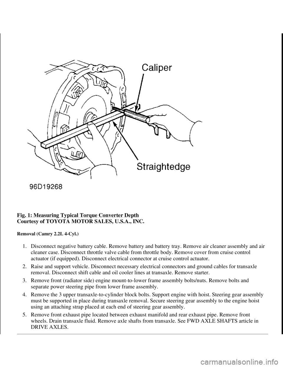
Fig. 1: Measuring Typical Torque Converter Depth
Courtesy of TOYOTA MOTOR SALES, U.S.A., INC.
Removal (Camry 2.2L 4-Cyl.)
1. Disconnect negative battery cable. Remove battery and battery tray. Remove air cleaner assembly and air
cleaner case. Disconnect throttle valve cable from throttle body. Remove cover from cruise control
actuator (if equipped). Disconnect electrical connector at cruise control actuator.
2. Raise and support vehicle. Disconnect necessary electrical connectors and ground cables for transaxle
removal. Disconnect shift cable and oil cooler lines at transaxle. Remove starter.
3. Remove front (radiator side) engine mount-to-lower frame assembly bolts/nuts. Remove bolts and
separate power steering pipe from lower frame assembly.
4. Remove the 3 upper transaxle-to-cylinder block bolts. Support engine with hoist. Steering gear assembly
must be supported in place during transaxle removal. Secure steering gear assembly to the engine hoist
using an attaching strap placed at each end of steering gear assembly.
5. Remove front exhaust pipe located between exhaust manifold and rear exhaust pipe. Remove front
wheels. Drain transaxle fluid. Remove axle shafts from transaxle. See FWD AXLE SHAFTS article in
DRIVE AXLES.
1998 Toyota Avalon XLS
TRANSMISSION SERVICING - A/T 1997-98 TRANSMISSION SERVICING Toyota - Transmission Removal &
Installation
Helpmelearn
November-03-08 10:30:28 AMPage 3 © 2005 Mitchell Repair Information Company, LLC.
Page 116 of 1632
6. Remove rear (firewall side) engine mount-to-lower frame assembly nuts. Remove transaxle mount-to-
transaxle bolts at driver's side end of transaxle.
7. Remove stabilizer bar mount bracket-to-lower frame assembly bolts. Remove steering gear assembly-to-
lower frame assembly bolts/nuts. Support lower frame assembly with floor jack. Lower frame assembly is
located below the engine and transaxle.
8. Remove bolts for each fender liner from lower frame assembly. Remove lower frame assembly mounting
brackets. Lower frame assembly mounting brackets are located on the front and rear of lower frame
assembly attaching the lower frame assembly to the body. Remove lower frame assembly.
9. Remove stiffener plates located on each side of cylinder block. Stiffener plate fits between side of
cylinder block and front of transaxle. Support transaxle with transmission jack.
10. Remove torque converter cover from front of transaxle. Remove Black torque converter bolt first and
then the remaining torque converter bolts. Remove remaining transaxle-to-cylinder block bolts. Lower
transaxle from vehicle.
Installation
1. Before installing transaxle, use dial indicator to check drive plate runout. Drive plate runout should be
checked right next to the starter ring gear on the drive plate. Replace drive plate if runout
exceeds .0079" (.200 mm).
2. Install torque converter on transaxle. To ensure torque converter is fully seated, torque converter depth
should be checked. Using straightedge and caliper, measure torque converter depth from torque converter
bolt lug on torque converter to the surface on transaxle. See Fig. 1
.
3. Torque converter depth should be more than .510" (13.00 mm). If torque converter depth is less than
specified, check for improperly seated torque converter.
4. To install, reverse removal procedure. Tighten all bolts/nuts to specification. See TORQUE
SPECIFICATIONS . When installing torque converter bolts, apply Loctite to torque converter bolt
threads before installing. Ensure the Black torque converter bolt is installed first before installing the
remaining torque converter bolts. Adjust all cables and fill with ATF. See appropriate TRANSMISSION
SERVICING article.
Removal (Camry 3.0L V6)
1. Disconnect negative battery cable. Remove battery, air cleaner assembly and air cleaner case. Disconnect
throttle valve cable from throttle body. Remove cruise control actuator with mounting bracket from the
body.
2. Raise and support vehicle. Disconnect necessary electrical connectors and ground cables for transaxle
removal. Disconnect shift cable and oil cooler lines at transaxle. Remove shift cable clamp bracket from
transaxle.
3. Remove front (radiator side) engine mount shock absorber-to-lower frame assembly bolts. Remove front
(radiator side) engine mount-to-lower frame assembly bolts/nuts. Remove starter.
4. Remove the 5 upper transaxle-to-cylinder block bolts. Support engine with hoist. Steering gear assembly
must be supported in place during transaxle removal. Secure steering gear assembly to the engine hoist
using an attaching strap placed at each end of steering gear assembly.
5. Remove front wheels. Remove front exhaust pipe located between exhaust manifolds and rear exhaust
1998 Toyota Avalon XLS
TRANSMISSION SERVICING - A/T 1997-98 TRANSMISSION SERVICING Toyota - Transmission Removal &
Installation
Helpmelearn
November-03-08 10:30:28 AMPage 4 © 2005 Mitchell Repair Information Company, LLC.
Page 121 of 1632
bolt lug on torque converter to the surface on transaxle. See Fig. 1.
3. Torque converter depth should be more than .898" (22.80 mm). If torque converter depth is less than
specified, check for improperly seated torque converter.
4. To install, reverse removal procedure. Tighten all bolts/nuts to specification. See TORQUE
SPECIFICATIONS . Tighten lower transaxle bolts to specification. See Fig. 3 .
5. When installing suspension crossmember, ensure all bolts and nuts are tightened to specification. See Fi
g.
2 .
6. When installing torque converter bolts, apply Loctite to torque converter bolt threads before installing.
Ensure the Gray torque converter bolt is installed first before installing the remaining torque converter
bolts.
7. Use NEW gaskets and NEW nuts when installing front exhaust pipe. Adjust all cables and fill with ATF.
See appropriate TRANSMISSION SERVICING article.
Removal (Celica 2.2L 5S-FE)
1. Disconnect negative battery cable. Remove battery. Disconnect throttle valve cable from throttle body.
Remove cruise control actuator (if equipped). Remover air cleaner assembly.
2. Remove transaxle-to-mount bolts/nuts from top of transaxle at driver's side end of transaxle. Remove
starter. Disconnect necessary ground cables and electrical connectors at transaxle.
3. Remove the 3 upper transaxle-to-cylinder block bolts located at top of transaxle. Disconnect oil cooler
lines for transaxle. Raise and support vehicle. Remove lower engine covers.
4. Support engine with hoist. Steering gear assembly must be supported in place during transaxle removal.
Secure steering gear assembly to the engine hoist using an attaching strap placed at each end of steering
gear assembly.
5. Remove front wheels. Drain transaxle fluid. Remove axle shafts from transaxle. See FWD AXLE
SHAFTS article in DRIVE AXLES.
6. Support transaxle with transmission jack. Disconnect shift cable at transaxle. Remove rear (firewall side)
engine mount through-bolt. Remove front exhaust pipe-to-front exhaust pipe support bracket bolts. Front
exhaust pipe is located between exhaust manifold and rear exhaust pipe.
7. Remove front exhaust pipe support bracket located between front exhaust pipe and front suspension
crossmember. Remove front exhaust pipe.
8. Remove shift cable brackets and A/C pipe from suspension crossmember. Suspension crossmember is
located below the engine and fits between both lower control arms. See Fig. 4
. Remove steering gear
assembly-to-suspension crossmember bolts.
9. Support suspension crossmember with floor jack. Remove grommets, engine mount crossmember and
suspension crossmember. See Fig. 4
.
10. Remove intake manifold brace located at bottom of intake manifold and stiffener plate. Remove stiffener
plate. Stiffener plate wraps around rear of oil pan and fits between sides of cylinder block and front of
transaxle.
11. Remove torque converter bolts. Remove 3 lower transaxle-to-cylinder block bolts. Lower transaxle from
vehicle.
1998 Toyota Avalon XLS
TRANSMISSION SERVICING - A/T 1997-98 TRANSMISSION SERVICING Toyota - Transmission Removal &
Installation
Helpmelearn
November-03-08 10:30:28 AMPage 9 © 2005 Mitchell Repair Information Company, LLC.
Page 126 of 1632
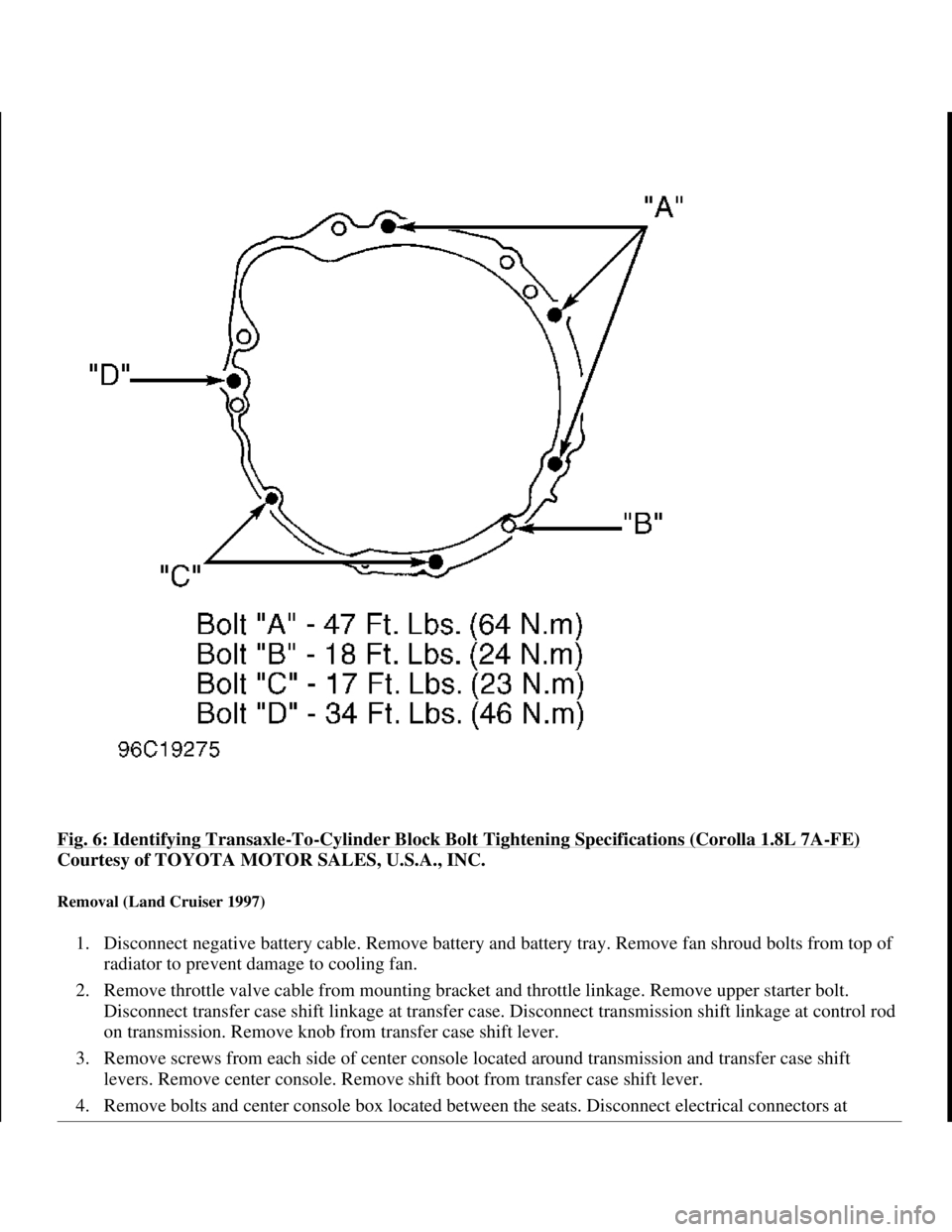
Fig. 6: Identifying Transaxle-To-Cylinder Block Bolt Tightening Specifications (Corolla 1.8L 7A-FE)
Courtesy of TOYOTA MOTOR SALES, U.S.A., INC.
Removal (Land Cruiser 1997)
1. Disconnect negative battery cable. Remove battery and battery tray. Remove fan shroud bolts from top of
radiator to prevent damage to cooling fan.
2. Remove throttle valve cable from mounting bracket and throttle linkage. Remove upper starter bolt.
Disconnect transfer case shift linkage at transfer case. Disconnect transmission shift linkage at control rod
on transmission. Remove knob from transfer case shift lever.
3. Remove screws from each side of center console located around transmission and transfer case shift
levers. Remove center console. Remove shift boot from transfer case shift lever.
4. Remove bolts and center console box located between the seats. Disconnect electrical connectors at
1998 Toyota Avalon XLS
TRANSMISSION SERVICING - A/T 1997-98 TRANSMISSION SERVICING Toyota - Transmission Removal &
Installation
Helpmelearn
November-03-08 10:30:28 AMPage 14 © 2005 Mitchell Repair Information Company, LLC.
Page 134 of 1632
5. Once engine and transaxle are installed, adjust all cables and fill with ATF. See appropriate
TRANSMISSION SERVICING article.
Removal (Sienna)
1. Disconnect negative battery cable. Remove hood. Remove wiper arms. Remove hood-to-cowl top seal.
Remove cowl panel hole cover. Remove clips and left and right side cowl top ventilator louvers.
Disconnect washer hoses. Remove 2 washer nozzles from cowl top ventilator louvers. Remove 11 bolts
and outer front cowl top panel.
2. Remove battery, battery tray, air cleaner assembly and air cleaner case. Disconnect throttle valve cable
from throttle body. Remove cruise control actuator with mounting bracket from the body.
3. Raise and support vehicle. Disconnect necessary electrical connectors and ground cables for transaxle
removal. Remove starter. Disconnect shift cable and oil cooler lines at transaxle. Remove shift cable
clamp bracket from transaxle.
4. Remove front (radiator side) engine mount shock absorber-to-lower frame assembly bolts. Remove front
(radiator side) engine mount-to-lower frame assembly bolts/nuts.
5. Remove front (radiator side) exhaust manifold brace from rear of exhaust manifolds. Brace fits between
rear of exhaust manifold and front of transaxle.
6. Remove the 5 upper transaxle-to-cylinder block bolts. Support engine with hoist. Steering gear assembly
must be supported in place during transaxle removal. Secure steering gear assembly to the engine hoist
using an attaching strap placed at each end of steering gear assembly.
7. Remove front wheels. Remove engine undercover. Remove front exhaust pipe located between exhaust
manifolds and rear exhaust pipe. Drain transaxle fluid. Remove axle shafts from transaxle. See FWD
AXLE SHAFTS article in DRIVE AXLES.
8. Disconnect shift control cable from mounting bracket. Remove rear (firewall side) engine mount-to-lower
frame assembly bolts/nuts. Remove transaxle mount-to-transaxle bolts/nuts at driver's side end of
transaxle.
9. Remove stabilizer bar mount bracket-to-lower frame assembly bolts. Remove steering gear assembly-to-
lower frame assembly bolts/nuts. Support lower frame assembly with floor jack. Lower frame assembly is
located below the engine and transaxle.
10. Disconnect power steering reservoir pipe mounting brackets from lower frame assembly. Remove lower
frame assembly mounting brackets. Lower frame assembly mounting brackets are located on the front
and rear of lower frame assembly attaching the lower frame assembly to the body. Remove lower frame
assembly.
11. Support transaxle with transmission jack. Remove torque converter bracket and cover bolts and nuts from
front of transaxle. Remove torque converter bolts. Remove remaining transaxle-to-cylinder block bolts.
Lower transaxle from vehicle.
Installation
NOTE: Wiper/washer components and output front cowl top panel must be
removed for clearance during transaxle removal and installation.
1998 Toyota Avalon XLS
TRANSMISSION SERVICING - A/T 1997-98 TRANSMISSION SERVICING Toyota - Transmission Removal &
Installation
Helpmelearn
November-03-08 10:30:29 AMPage 22 © 2005 Mitchell Repair Information Company, LLC.
Page 164 of 1632
1. If shift lever is actuated with engine idling, a time lag will be noted before shock can be felt. This test is
used for checking condition of OD direct clutch, forward clutch, direct clutch, and 1st and reverse brake.
2. Apply parking brake. Start engine. On RAV4, ensure idle speed is 700-800 RPM. On all other models,
ensure idle speed is 650-750 RPM. Shift transaxle from "N" into "D" range. Use a stop watch to measure
elapsed time between shifting of lever until shock is felt. Standard time lag is less than 1.2 seconds.
3. Repeat procedure outlined in step 2) to measure time lag for "N" to "R". Standard lag time is less than 1.5
seconds.
4. If "N" to "D" time lag is longer than specification, line pressure is too low, forward clutch may be worn,
or OD one-way clutch is not operating properly.
5. If "N" to "R" time lag is longer than specified, direct clutch may be worn, 1st and reverse brake may be
worn, line pressure is too low or OD one-way clutch is not operating properly.
ROAD TEST
"D" Range Test In NORM & PWR Pattern Ranges
1. Shift into "D" range. Hold accelerator pedal constant at full throttle. Place shift mode button in NORM or
PWR position. Check 1-2, 2-3, and 3-OD lock-up and upshift points. See appropriate table under SHIFT
SPEED SPECIFICATIONS .
�zIf no 1-2 upshift occurs, check 1-2 shift valve or solenoid.
�zIf no 2-3 upshift occurs, check 2-3 shift valve or solenoid.
�zIf no 3-OD upshift occurs, check 3-OD shift valve.
�zIf all shift points are incorrect, check throttle valve, 1-2 shift valve, 2-3 shift valve and 3-OD shift
valve.
�zIf all lock-up points are incorrect, check lock-up relay valve or shift solenoid valve SL.
2. Use procedure outlined in step 1) to check for shock and slip between 1-2, 2-3, and 3-OD upshifts. If
shock is harsh, line pressure may be too high. Check accumulator or check ball.
3. Run vehicle in "D" range lock-up or overdrive gear. Check for abnormal noise and vibration.
4. While running in "D" range, confirm correct kickdown vehicle speed limits for 2-1, 3-2, OD-3 shift
points. Check for abnormal shock and slip at kickdown.
5. Check loc
k-up function. Drive vehicle in OD gear of "D" range with lock-up on. Hold vehicle speed NOTE: Perform test at normal operating fluid temperature of 122-176°F (50-80°C).
NOTE: There is no overdrive upshift when coolant temperature is below 140°F
(60°C). There is no lock-up when vehicle speed is 6 MPH less than the set
cruise control speed.
NOTE: Check for cause of abnormal noise and vibration must be made with
extreme care as problem could be due to an unbalanced drive shaft,
differential, tire, torque converter, etc.
1998 Toyota Avalon XLS
1997-99 AUTOMATIC TRANSMISSIONS Toyota A-540E, A-540H & A-541E Overhaul
Helpmelearn
November-03-08 10:28:17 AMPage 10 © 2005 Mitchell Repair Information Company, LLC.
Page 269 of 1632
step 2). If throttle valve is not fully open, adjust throttle linkage or cable so throttle valve is fully open and
then go to step 2).
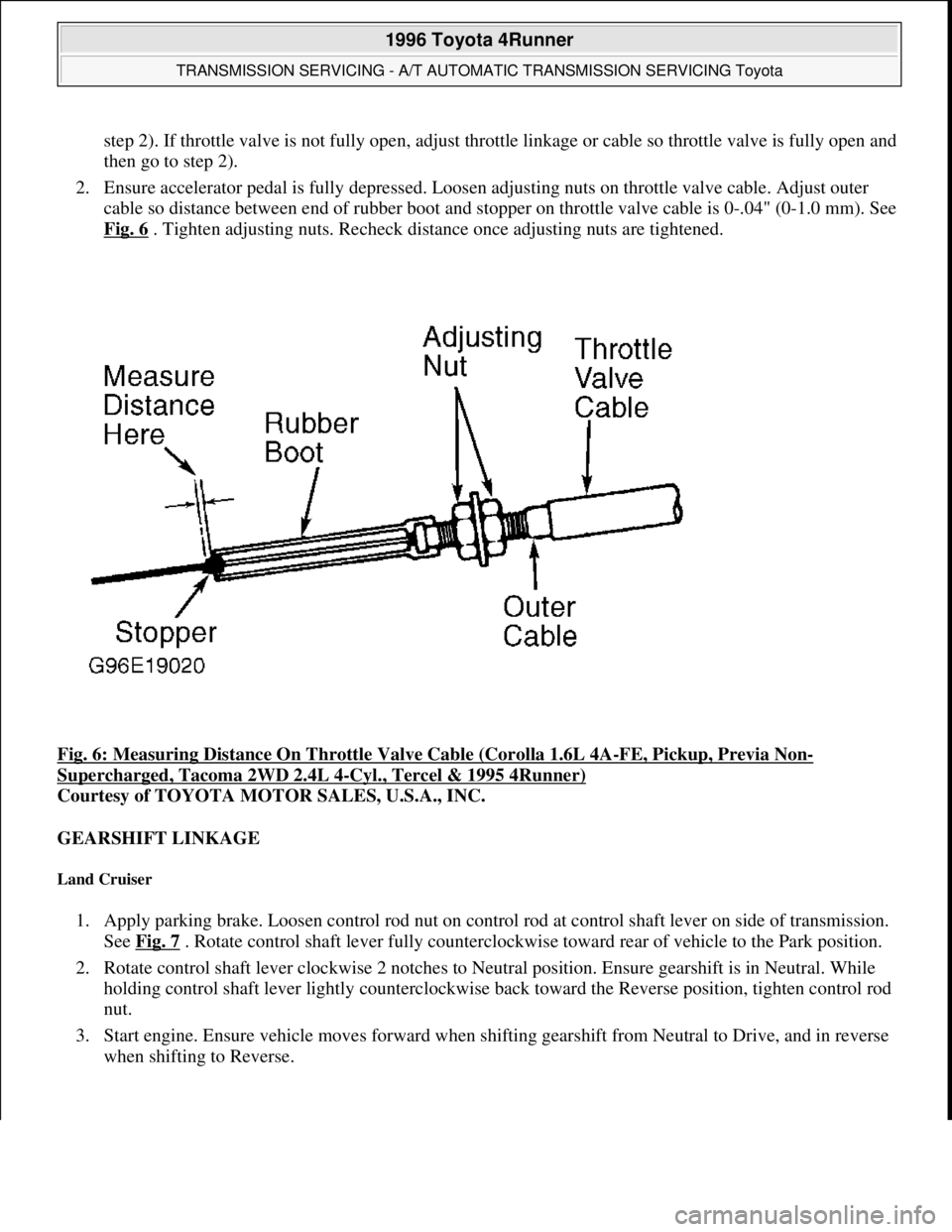
2. Ensure accelerator pedal is fully depressed. Loosen adjusting nuts on throttle valve cable. Adjust outer
cable so distance between end of rubber boot and stopper on throttle valve cable is 0-.04" (0-1.0 mm). See
Fig. 6
. Tighten adjusting nuts. Recheck distance once adjusting nuts are tightened.
Fig. 6: Measuring Distance On Throttle Valve Cable (Corolla 1.6L 4A
-FE, Pickup, Previa Non-
Supercharged, Tacoma 2WD 2.4L 4-Cyl., Tercel & 1995 4Runner)
Courtesy of TOYOTA MOTOR SALES, U.S.A., INC.
GEARSHIFT LINKAGE
Land Cruiser
1. Apply parking brake. Loosen control rod nut on control rod at control shaft lever on side of transmission.
See Fig. 7
. Rotate control shaft lever fully counterclockwise toward rear of vehicle to the Park position.
2. Rotate control shaft lever clockwise 2 notches to Neutral position. Ensure gearshift is in Neutral. While
holding control shaft lever lightly counterclockwise back toward the Reverse position, tighten control rod
nut.
3. Start engine. Ensure vehicle moves forward when shifting gearshift from Neutral to Drive, and in reverse
when shiftin
g to Reverse.
1996 Toyota 4Runner
TRANSMISSION SERVICING - A/T AUTOMATIC TRANSMISSION SERVICING Toyota
Microsoft
Tuesday, August 18, 2009 7:18:46 PMPage 13 © 2005 Mitchell Repair Information Company, LLC.
Page 270 of 1632
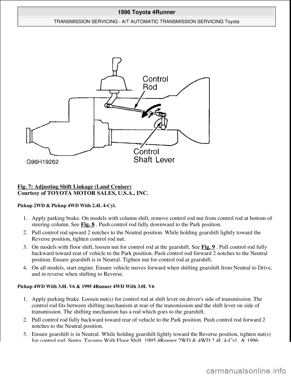
Fig. 7: Adjusting Shift Linkage (Land Cruiser)
Courtesy of TOYOTA MOTOR SALES, U.S.A., INC.
Pickup 2WD & Pickup 4WD With 2.4L 4-Cyl.
1. Apply parking brake. On models with column shift, remove control rod nut from control rod at bottom of
steering column. See Fig. 8
. Push control rod fully downward to the Park position.
2. Pull control rod upward 2 notches to the Neutral position. While holding gearshift lightly toward the
Reverse position, tighten control rod nut.
3. On models with floor shift, loosen nut for control rod at the gearshift. See Fig. 9
. Pull control rod fully
backward toward rear of vehicle to the Park position. Push control rod forward 2 notches to the Neutral
position. Ensure gearshift is in Neutral. Tighten nut for control rod at gearshift.
4. On all models, start engine. Ensure vehicle moves forward when shifting gearshift from Neutral to Drive,
and in reverse when shifting to Reverse.
Pickup 4WD With 3.0L V6 & 1995 4Runner 4WD With 3.0L V6
1. Apply parking brake. Loosen nut(s) for control rod at shift lever on driver's side of transmission. The
control rod fits between shifting mechanism at rear of the transmission and the shift lever on side of
transmission. The shifting mechanism has a rod which goes to the gearshift.
2. Pull control rod fully backward toward rear of vehicle to the Park position. Push control rod forward 2
notches to the Neutral position.
3. Ensure gearshift is in Neutral. While holding gearshift lightly toward the Reverse position, tighten nut(s)
for control rod. Supra, Tacoma With Floor Shift, 1995 4Runner 2WD & 4WD 2.4L 4-C
yl., & 1996
1996 Toyota 4Runner
TRANSMISSION SERVICING - A/T AUTOMATIC TRANSMISSION SERVICING Toyota
Microsoft
Tuesday, August 18, 2009 7:18:46 PMPage 14 © 2005 Mitchell Repair Information Company, LLC.