oil pressure TOYOTA RAV4 1996 Service Repair Manual
[x] Cancel search | Manufacturer: TOYOTA, Model Year: 1996, Model line: RAV4, Model: TOYOTA RAV4 1996Pages: 1632, PDF Size: 41.64 MB
Page 14 of 1632
DTC 21, DTC 22, DTC 23 & DTC 24: ABS ACTUATOR SOLENOID CIRCUIT
Circuit Description
This solenoid turns on when signals are received from ABS ECU and controls pressure acting on calipers/wheel
cylinders, thus controlling braking force. If malfunction occurs in actuator solenoid circuit, ABS ECU cuts off
current to ABS control relay and prohibits ABS control.
DTC Detecting Conditions
If the following conditions continue for .05 seconds or more, DTC will set. Voltage at ABS control relay
connector terminal A9-1 is less than 1.5 volts, and one of the following conditions is met:
If power transistor of ABS ECU is on, and voltage at terminal SFRR or terminal SFRH is zero volts or
battery voltage is detected, DTC 21 will set.
If power transistor of ABS ECU is on, and voltage at terminal SFLR or terminal SFLH is zero volts or
battery voltage is detected, DTC 22 will set.
If power transistor of ABS ECU is on, and voltage at terminal SRRR or terminal SRRH is zero volts or
battery voltage is detected, DTC 23 will set.
If power transistor of ABS ECU is on, and voltage at terminal SRLR or terminal SRLH is zero volts or
battery voltage is detected, DTC 24 will set.
Diagnostic Procedure
1. Disconnect 2 ABS actuator connectors. Check continuity between actuator connector terminal A7- 4 and
actuator connector terminals A6-1 through A6-8. See Fig. 6
. Continuity should exist at each pair of
terminals. Check resistance at each pair of terminals. Resistance should be 4.3 ohms for each solenoid
coil at terminals SFRR, SFLR, SRRR and SRLR. Resistance should be 8.8 ohms for each solenoid coil at
terminals SFRH, SFLH, SRRH and SRLH. See WIRING DIAGRAMS
. If continuity and resistance is
as specified, go to next step. If continuity and resistance is not as specified, replace ABS actuator.
2. Check for open or short circuit in wiring harness between ABS ECU and actuator. Repair as necessary.
See WIRING DIAGRAMS
. If circuits are okay, go to next step.
3. Clear DTCs and then recheck for DTCs. See RETRIEVING DTCS
under DIAGNOSIS & TESTING. If
same DTC is output after DTC is cleared, check contact condition of each connection. Repair as
necessar
y. If connections are okay, replace ABS ECU.
1999 Toyota RAV4
1999-2000 BRAKES Anti-Lock - RAV4
Microsoft
Sunday, November 22, 2009 10:06:17 AMPage 14 © 2005 Mitchell Repair Information Company, LLC.
Page 171 of 1632
HYDRAULIC PRESSURE TEST
Line Pressure Test
1. Ensure transmission fluid is at operating temperature. Raise and support vehicle. Remove transaxle case
test plug and install pressure gauge. See Fig. 5
. Lower vehicle and block all wheels.
2. Fully apply parking brake. Start engine. Apply brakes. Shift into "D" range. On A-540H transaxle, apply
battery voltage between ground and terminal No. 1 of shift solenoid valve ST connector. See Fig. 6
. On
all transaxles, measure line pressure at idle. Accelerate to full throttle. Measure line pressure at stall
speed. See appropriate LINE PRESSURE SPECIFICATIONS table.
3. On all models, repeat test in "R" range. DO NOT ground shift solenoid valve ST in "R" range.
4. If pressures exceed specifications in all ranges, regulator valve or throttle valve is faulty or throttle cable
is out of adjustment.
5. If pressures in all ranges are lower than specifications, oil pump, regulator valve, throttle valve or OD
direct clutch is faulty or throttle cable is out of adjustment.
6. If pressure is lower than specifications in "D" range only, forward clutch is faulty or "D" range circuit has
a fluid leak.
7. If pressure is lower than specifications in "R" range only, direct clutch is faulty, 1st and reverse brake is
faulty or "R" range circuit has a fluid leak.
LINE PRESSURE SPECIFICATIONS (A-540E)
LINE PRESSURE SPECIFICATIONS (A-540H) 1997
(1)
CAUTION: Hydraulic pressure test should be performed with transmission fluid
temperature of 122-176°F (50-80°C).
Selector PositionPressure - psi (kg/cm2 )
"D" Position
Idle Speed51-60 (3.6-4.2)
Stall Speed127-148 (8.9-10.4)
"R" Position
Idle Speed93-108 (6.5-7.6)
Stall Speed230-268 (16.1-18.8)
Selector PositionPressure - psi (kg/cm2 )
"D" Position
Idle Speed
With Solenoid Valve ST On76-102 (5.4-7.2)
With Solenoid Valve ST Off53-61 (3.7-4.3)
Stall Speed
With Solenoid Valve ST On192-225 (13.5-15.8)
With Solenoid Valve ST Off106-125 (7.5-8.8)
1998 Toyota Avalon XLS
1997-99 AUTOMATIC TRANSMISSIONS Toyota A-540E, A-540H & A-541E Overhaul
Helpmelearn
November-03-08 10:28:17 AMPage 17 © 2005 Mitchell Repair Information Company, LLC.
Page 177 of 1632
washer. Remove nut and washer. Remove Park/Neutral Position (PNP) switch.
3. Remove throttle cable retaining bolt. Remove solenoid harness connector retaining bolt (if applicable).
Remove vehicle speed sensor mounted in differential cover. Remove sensor adapter. Remove direct
clutch speed (T/M revolution) sensor mounted to upper case cover (if equipped). Remove upper case
cover. Remove transaxle oil pan. Examine any contamination in pan to aid in diagnosis.
4. Remove oil stainer (filter) and oil pipe hold-down bracket. Remove manual valve body including detent
spring. Gently remove all oil pipes by prying up on end of pipe with screwdriver.
5. Disconnect solenoid harness connectors. Remove connector clamp and apply pipe retainer. Remove 1st
and reverse apply pipe. Remove valve body bolts. Remove wiring harness clamp. Disconnect throttle
cable from cam and remove valve body.
6. Remove throttle cable and solenoid wiring harness. Remove 2nd brake apply gasket. Loosen accumulator
cover bolts in crisscross pattern. Remove cover and gasket. Remove forward clutch accumulator. See Fi
g.
10 .
7. Remove remaining accumulators by applying 14 psi (1kg/cm
2 ) of air pressure to apply hole. See Fig.
11 . Cover accumulator bores with a rag when applying air.
8. Mark 2nd coast brake servo apply piston rod where it meets case. Apply 57-114 psi (4-8 kg/cm
2 ) of air
pressure to apply hole and measure piston rod travel (stroke). See Fig. 12
. Piston rod travel should
be .079-.138" (2.0-3.5 mm). If rod travel is not within specification, further inspect band during
disassembly.
9. Remove 2nd coast brake piston cover snap ring. Apply air to oil hole and remove cover and piston
assembly. See Fig. 12
. Remove oil pump bolts. Using appropriate puller, remove oil pump.
10. Remove direct clutch and forward clutch. Separate components and remove thrust washer. Remove thrust
bearings from front and rear of forward clutch. Push out 2nd coast brake band anchor pin. Remove band
and inspect.
11. Remove front planetary ring gear. Remove front planetary gear with thrust bearings on either side.
Remove thrust bearings. Remove sun gear shell with thrust washer.
12. Apply compressed air to 2nd brake piston port and check operation of 2nd brake. See Fig. 13
. Remove
2nd coast brake band guide. DO NOT separate band guide and bolt. Remove snap ring securing 2nd
brake drum. Remove drum.
13. Remove 2nd brake piston return spring. Remove No. 1 one-way clutch. Remove 2nd brake clutch discs,
plates and flange. Note number and location of components. Remove snap ring securing No. 2 one-way
clutch and rear planetary gear. See Fig. 14
. Remove components.
14. Remove thrust washer from rear planetary gear. Remove rear planetary ring gear with thrust bearing.
Apply air into appropriate passage to check 1st and reverse brake operation. See Fig. 15
.
15. Using feeler gauge, check pack clearance of 1st and reverse brake assembly. Clearance should be .033-
.081" (.85-2.05 mm) for A-540E transaxle, .041-.085" (1.04-2.16 mm) for A-540H transaxle, or .076-
.106" (1.92-2.68 mm) for A-541E transaxle. Remove snap ring securing 1st and reverse brake. Remove
1st and reverse brake discs, plates and flange. Note number and location of components.
16. From back of transaxle, remove 13 bolts securing overdrive unit. Using soft-faced hammer, tap around
outside of case until overdrive unit loosens and can be removed.
17. Remove overdrive (OD) planetary gear from transaxle case. Remove OD brake drum. See Fig. 14
.
Remove gaskets for OD clutch apply and OD brake apply ports.
18. Usin
g appropriate compressor, compress 1st and reverse piston. See Fig. 16 . Remove snap ring. Apply
1998 Toyota Avalon XLS
1997-99 AUTOMATIC TRANSMISSIONS Toyota A-540E, A-540H & A-541E Overhaul
Helpmelearn
November-03-08 10:28:17 AMPage 23 © 2005 Mitchell Repair Information Company, LLC.
Page 188 of 1632
Disassembly
1. Prior to disassembly, check piston stroke of direct clutch. Measure piston stroke by applying 57-114 psi
(4-8 kg/cm
2 ) of compressed air. See Fig. 20 . Piston stroke should be .036-.053" (.91-1.35 mm) for A-
540E and A-541E transaxles or .044-.058" (1.11-1.47 mm) for A-540H transaxle. If piston stroke is
greater than maximum, inspect each component.
2. Remove snap ring from clutch drum. Remove flange, discs and plates. Note number and location of
components. See Fig. 21
. Compress piston return springs and remove snap ring. Remove spring retainer.
Slide direct clutch onto oil pump. Remove piston by applying low pressure compressed air. See Fig. 20
.
Remove direct clutch from oil pump. Remove "O" ring from clutch piston.
Inspection
Shake piston to ensure direct clutch piston check ball is free. Ensure valve does not leak by applying low
pressure compressed air. Inspect discs, plates and flange. Measure inside diameter of direct clutch bushing.
Maximum inside diameter is 1.900" (48.27 mm) for A-540E and A-541E transaxles or 1.853" (47.07 mm) for
A-540H transaxle. If inside diameter is excessive, replace direct clutch.
Reassembly
1. Install NEW "O" rings on piston. Coat rings with ATF. Press piston in drum with cup side up. Ensure "O"
ring is not damaged. Install piston return springs. Install retainer and snap ring.
2. Install plates, discs and flange. Install flange with flat side facing inward. Install outer snap ring. Ensure
end gap of snap ring is not aligned with cut-outs in direct clutch drum.
3. Install direct clutch on oil pump. Check piston stroke. Using a dial indicator, measure piston stroke by
applying and releasing 57-114 psi (4-8 kg/cm
2 ) of compressed air. See Fig. 20 .
4. Piston stroke should be .036-.053" (.91-1.35 mm) for A-540E and A-541E transaxles or .044-.058" (1.11-
1.47 mm) for A-540H transaxle. If piston stroke is less than specification, replace flange. Flange is
available in thicknesses of .106" (2.70 mm) and .118" (3.00 mm) for A-540E and A-541E transaxles
or .102" (2.60 mm), .110" (2.80 mm) and .118" (3.00 mm) for A-540H transaxle.
1998 Toyota Avalon XLS
1997-99 AUTOMATIC TRANSMISSIONS Toyota A-540E, A-540H & A-541E Overhaul
Helpmelearn
November-03-08 10:28:18 AMPage 34 © 2005 Mitchell Repair Information Company, LLC.
Page 191 of 1632
piston. If piston does not come out, remove piston with needle-nose pliers. Remove oil seal rings (if
necessary).
Inspection
Inspect clutch piston. Shake piston to ensure check ball is free. Ensure valve does not leak by applying low
pressure compressed air. Replace oil seal rings (if removed). DO NOT spread ring ends more than required for
installation. Inspect discs, plates and flanges.
Reassembly
1. Coat NEW "O" rings with ATF. Install "O" rings on piston. Press piston into drum with cup side up.
Ensure "O" ring is not damaged.
2. Install return springs, retainer and snap ring in drum. Compress retainer using compressor. Using pliers,
install snap ring in groove. Ensure end gap of snap ring is not aligned with spring retainer claw.
3. Install plates, discs and flange. Install flange with flat end facing inward. Install outer snap ring. Ensure
end gap of ring is not aligned with cut-outs in clutch drum.
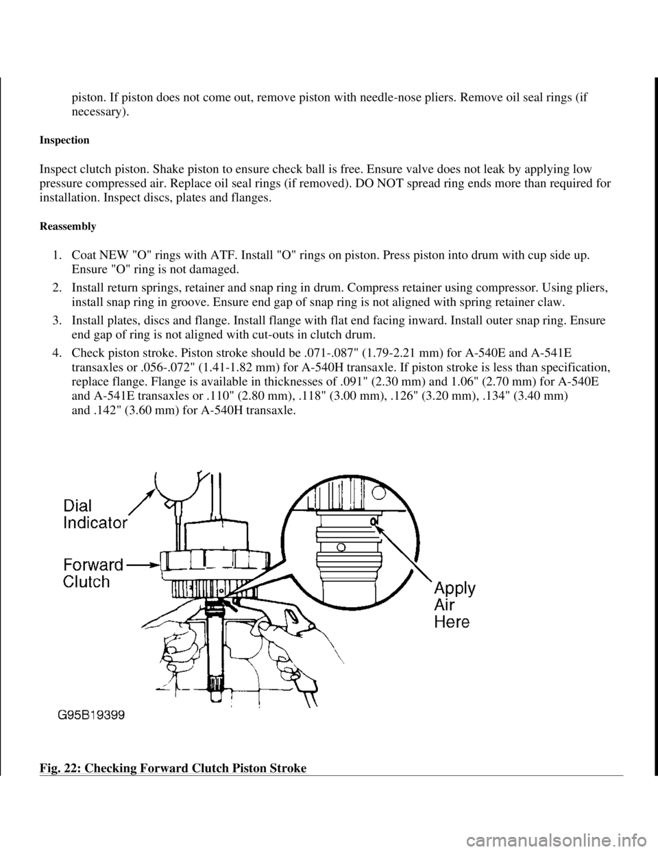
4. Check piston stroke. Piston stroke should be .071-.087" (1.79-2.21 mm) for A-540E and A-541E
transaxles or .056-.072" (1.41-1.82 mm) for A-540H transaxle. If piston stroke is less than specification,
replace flange. Flange is available in thicknesses of .091" (2.30 mm) and 1.06" (2.70 mm) for A-540E
and A-541E transaxles or .110" (2.80 mm), .118" (3.00 mm), .126" (3.20 mm), .134" (3.40 mm)
and .142" (3.60 mm) for A-540H transaxle.
Fig. 22: Checking Forward Clutch Piston Stroke
1998 Toyota Avalon XLS
1997-99 AUTOMATIC TRANSMISSIONS Toyota A-540E, A-540H & A-541E Overhaul
Helpmelearn
November-03-08 10:28:18 AMPage 37 © 2005 Mitchell Repair Information Company, LLC.
Page 198 of 1632
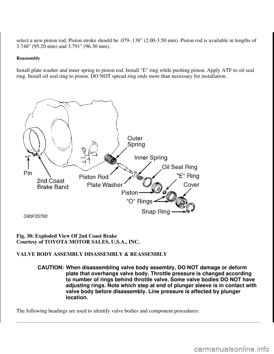
select a new piston rod. Piston stroke should be .079-.138" (2.00-3.50 mm). Piston rod is available in lengths of
3.748" (95.20 mm) and 3.791" (96.30 mm).
Reassembly
Install plate washer and inner spring to piston rod. Install "E" ring while pushing piston. Apply ATF to oil seal
ring. Install oil seal ring to piston. DO NOT spread ring ends more than necessary for installation.
Fig. 30: Exploded View Of 2nd Coast Brake
Courtesy of TOYOTA MOTOR SALES, U.S.A., INC.
VALVE BODY ASSEMBLY DISASSEMBLY & REASSEMBLY
The followin
g headings are used to identify valve bodies and component procedures:
CAUTION: When disassembling valve body assembly, DO NOT damage or deform
plate that overhangs valve body. Throttle pressure is changed according
to number of rings behind throttle valve. Some valve bodies DO NOT have
adjusting rings. Note which step at end of plunger sleeve is in contact with
valve body before disassembly. Line pressure is affected by plunger
location.
1998 Toyota Avalon XLS
1997-99 AUTOMATIC TRANSMISSIONS Toyota A-540E, A-540H & A-541E Overhaul
Helpmelearn
November-03-08 10:28:18 AMPage 44 © 2005 Mitchell Repair Information Company, LLC.
Page 202 of 1632
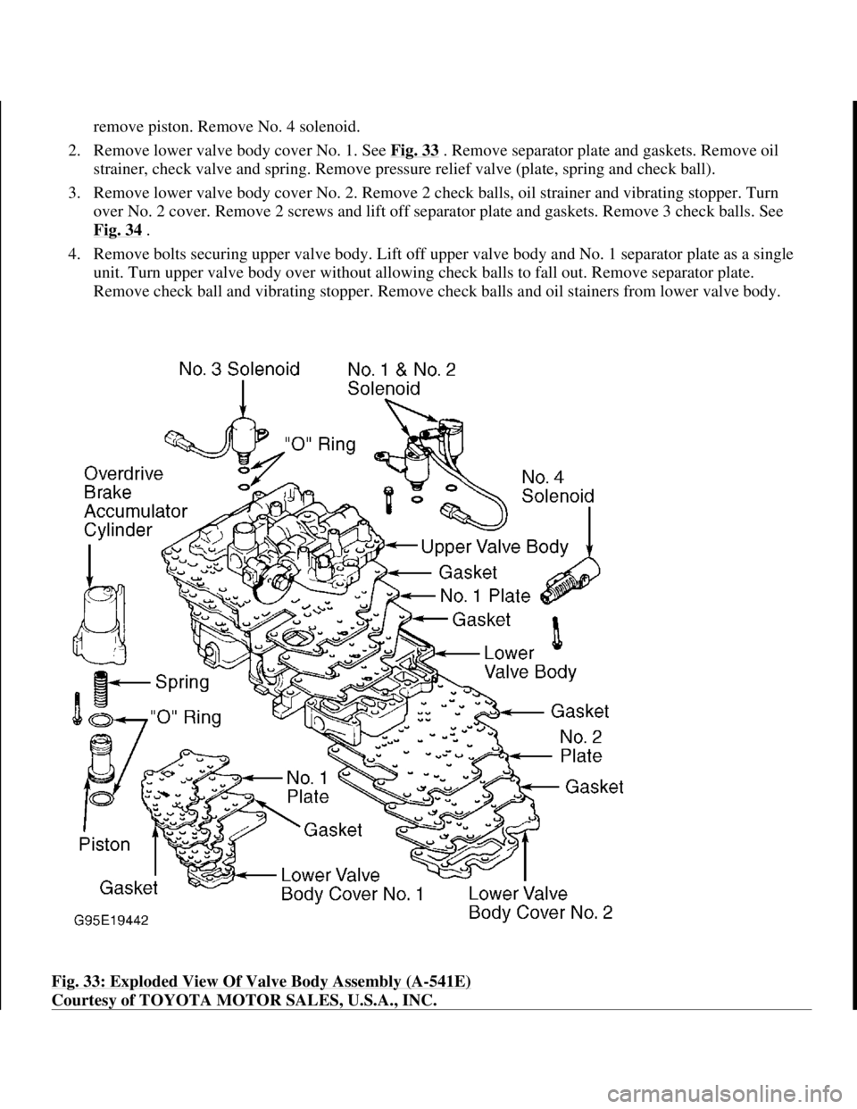
remove piston. Remove No. 4 solenoid.
2. Remove lower valve body cover No. 1. See Fig. 33
. Remove separator plate and gaskets. Remove oil
strainer, check valve and spring. Remove pressure relief valve (plate, spring and check ball).
3. Remove lower valve body cover No. 2. Remove 2 check balls, oil strainer and vibrating stopper. Turn
over No. 2 cover. Remove 2 screws and lift off separator plate and gaskets. Remove 3 check balls. See
Fig. 34
.
4. Remove bolts securing upper valve body. Lift off upper valve body and No. 1 separator plate as a single
unit. Turn upper valve body over without allowing check balls to fall out. Remove separator plate.
Remove check ball and vibrating stopper. Remove check balls and oil stainers from lower valve body.
Fig. 33: Exploded View Of Valve Body Assembly (A
-541E)
Courtesy of TOYOTA MOTOR SALES, U.S.A., INC.
1998 Toyota Avalon XLS
1997-99 AUTOMATIC TRANSMISSIONS Toyota A-540E, A-540H & A-541E Overhaul
Helpmelearn
November-03-08 10:28:18 AMPage 48 © 2005 Mitchell Repair Information Company, LLC.
Page 206 of 1632
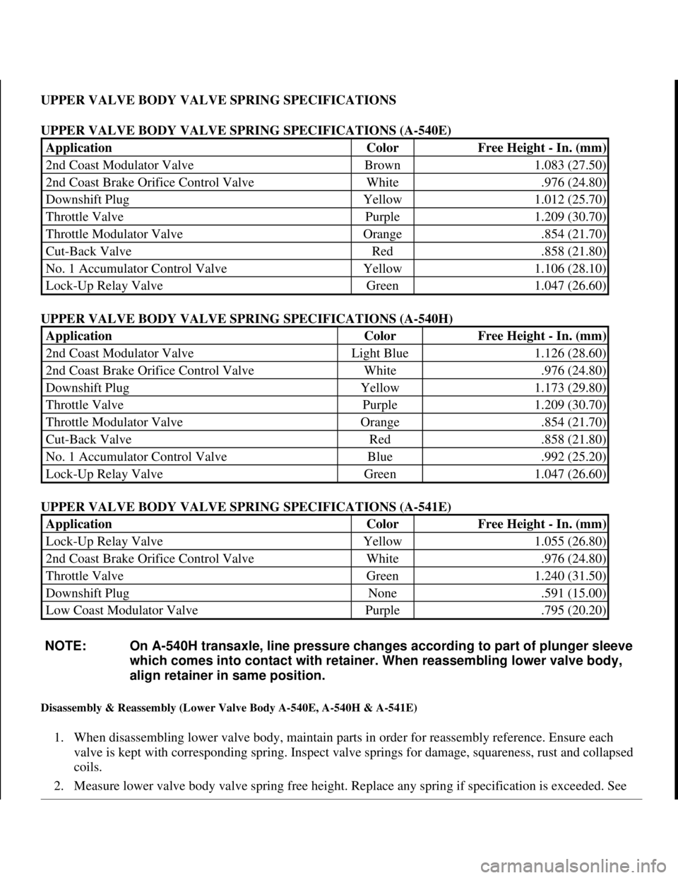
UPPER VALVE BODY VALVE SPRING SPECIFICATIONS
UPPER VALVE BODY VALVE SPRING SPECIFICATIONS (A-540E)
UPPER VALVE BODY VALVE SPRING SPECIFICATIONS (A-540H)
UPPER VALVE BODY VALVE SPRING SPECIFICATIONS (A-541E)
Disassembly & Reassembly (Lower Valve Body A-540E, A-540H & A-541E)
1. When disassembling lower valve body, maintain parts in order for reassembly reference. Ensure each
valve is kept with corresponding spring. Inspect valve springs for damage, squareness, rust and collapsed
coils.
2. Measure lower valve bod
y valve spring free height. Replace any spring if specification is exceeded. See
ApplicationColorFree Height - In. (mm)
2nd Coast Modulator ValveBrown1.083 (27.50)
2nd Coast Brake Orifice Control ValveWhite.976 (24.80)
Downshift PlugYellow1.012 (25.70)
Throttle ValvePurple1.209 (30.70)
Throttle Modulator ValveOrange.854 (21.70)
Cut-Back ValveRed.858 (21.80)
No. 1 Accumulator Control ValveYellow1.106 (28.10)
Lock-Up Relay ValveGreen1.047 (26.60)
ApplicationColorFree Height - In. (mm)
2nd Coast Modulator ValveLight Blue1.126 (28.60)
2nd Coast Brake Orifice Control ValveWhite.976 (24.80)
Downshift PlugYellow1.173 (29.80)
Throttle ValvePurple1.209 (30.70)
Throttle Modulator ValveOrange.854 (21.70)
Cut-Back ValveRed.858 (21.80)
No. 1 Accumulator Control ValveBlue.992 (25.20)
Lock-Up Relay ValveGreen1.047 (26.60)
ApplicationColorFree Height - In. (mm)
Lock-Up Relay ValveYellow1.055 (26.80)
2nd Coast Brake Orifice Control ValveWhite.976 (24.80)
Throttle ValveGreen1.240 (31.50)
Downshift PlugNone.591 (15.00)
Low Coast Modulator ValvePurple.795 (20.20)
NOTE: On A-540H transaxle, line pressure changes according to part of plunger sleeve
which comes into contact with retainer. When reassembling lower valve body,
align retainer in same position.
1998 Toyota Avalon XLS
1997-99 AUTOMATIC TRANSMISSIONS Toyota A-540E, A-540H & A-541E Overhaul
Helpmelearn
November-03-08 10:28:18 AMPage 52 © 2005 Mitchell Repair Information Company, LLC.
Page 216 of 1632
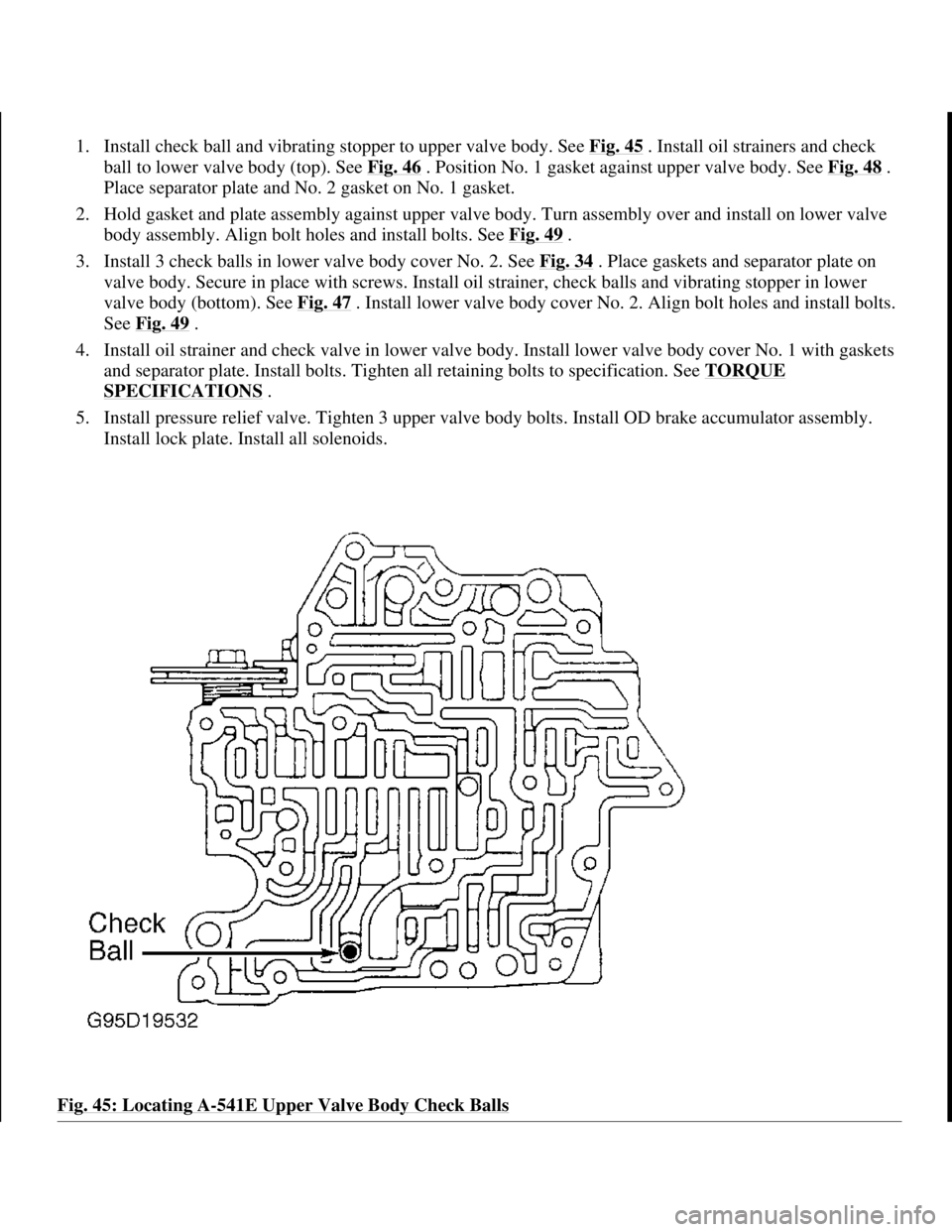
1. Install check ball and vibrating stopper to upper valve body. See Fig. 45 . Install oil strainers and check
ball to lower valve body (top). See Fig. 46
. Position No. 1 gasket against upper valve body. See Fig. 48 .
Place separator plate and No. 2 gasket on No. 1 gasket.
2. Hold gasket and plate assembly against upper valve body. Turn assembly over and install on lower valve
body assembly. Align bolt holes and install bolts. See Fig. 49
.
3. Install 3 check balls in lower valve body cover No. 2. See Fig. 34
. Place gaskets and separator plate on
valve body. Secure in place with screws. Install oil strainer, check balls and vibrating stopper in lower
valve body (bottom). See Fig. 47
. Install lower valve body cover No. 2. Align bolt holes and install bolts.
See Fig. 49
.
4. Install oil strainer and check valve in lower valve body. Install lower valve body cover No. 1 with gaskets
and separator plate. Install bolts. Tighten all retaining bolts to specification. See TORQUE
SPECIFICATIONS .
5. Install pressure relief valve. Tighten 3 upper valve body bolts. Install OD brake accumulator assembly.
Install lock plate. Install all solenoids.
Fig. 45: Locating A
-541E Upper Valve Body Check Balls
1998 Toyota Avalon XLS
1997-99 AUTOMATIC TRANSMISSIONS Toyota A-540E, A-540H & A-541E Overhaul
Helpmelearn
November-03-08 10:28:19 AMPage 62 © 2005 Mitchell Repair Information Company, LLC.
Page 440 of 1632
plate. Install a new clutch plate bolt and tighten to 97-123 INCH lbs. (11-14 N.m).
4. On Nissan Quest, install dial indicator at clutch plate and set to zero. Energize clutch coil and measure air
gap between clutch plate and pulley. Air gap should be 0.020-0.033" (0.45-0.85 mm).
5. On Hyundai and Mazda, use a feeler gauge to check air gap between clutch plate and pulley at 3 places
around pulley. On Hyundai, air gap should be 0.016-0.024" (0.41-0.61 mm).
6. On Mazda, air gap should be 0.014-0.033" (0.35-0.84 mm). On all models, if air gap is incorrect, add or
remove shims as necessary.
SHAFT SEAL
Removal
1. Hold clutch plate stationary and remove clutch plate center bolt. Remove clutch plate. If clutch plate
cannot be removed by hand, use an 8 x 1.25-mm bolt threaded into clutch plate to remove clutch plate
and shim(s). See Fig. 2
.
2. Remove shaft seal felt from nose of compressor. Thoroughly clean seal area of compressor using low-
pressure compressed air and a lint-free cloth. Remove compressor shaft seal internal snap ring. Position
shaft seal remover over compressor shaft.
3. Push shaft seal remover downward against seal. Ensure end of shaft seal remover is engaged with inside
of seal. Hold hex part of seal remover and rotate shaft seal remover handle clockwise to expand remover
tip inside seal. Pull shaft seal from compressor.
Installation
1. Lubricate shaft seal protector and shaft seal with refrigerant oil. Install shaft seal on shaft seal protector so
lip seal is toward compressor (large end of shaft seal protector).
2. Install shaft seal protector on compressor shaft. Using shaft seal installer, push shaft seal down seal
protector until seal is seated.
3. Remove shaft seal installer and protector. Install a new shaft seal snap ring and shaft seal felt. Install shim
(s) and clutch plate. Install a new clutch plate bolt and tighten to 97-123 INCH lbs. (11-14 N.m).
4. Use a feeler gauge to check air gap between clutch plate and pulley at 3 places around pulley. On
Hyundai Accent, air gap should be 0.016-0.024" (0.41-0.61 mm).
5. On all other models, air gap should be 0.014-0.033" (0.35-0.84 mm). If air gap is incorrect, add or remove
shims as necessary.
1999 Toyota RAV4
1999 GENERAL SERVICING Compressor Servicing
Microsoft
Sunday, November 22, 2009 10:31:50 AMPage 3 © 2005 Mitchell Repair Information Company, LLC.