valve clearance TOYOTA RAV4 1996 Service Owner's Guide
[x] Cancel search | Manufacturer: TOYOTA, Model Year: 1996, Model line: RAV4, Model: TOYOTA RAV4 1996Pages: 1632, PDF Size: 41.64 MB
Page 806 of 1632
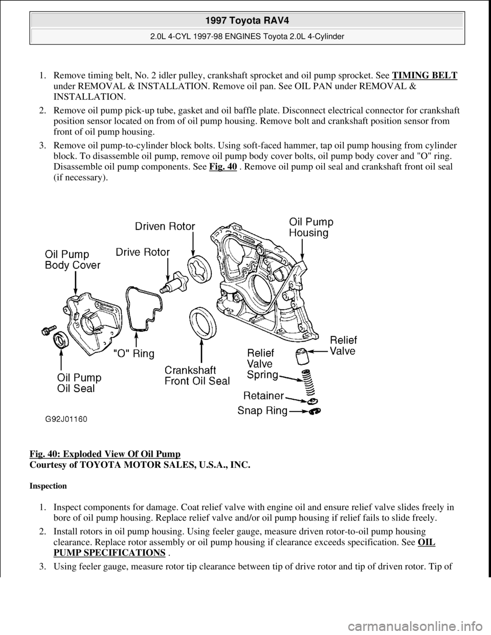
1. Remove timing belt, No. 2 idler pulley, crankshaft sprocket and oil pump sprocket. See TIMING BELT
under REMOVAL & INSTALLATION. Remove oil pan. See OIL PAN under REMOVAL &
INSTALLATION.
2. Remove oil pump pick-up tube, gasket and oil baffle plate. Disconnect electrical connector for crankshaft
position sensor located on from of oil pump housing. Remove bolt and crankshaft position sensor from
front of oil pump housing.
3. Remove oil pump-to-cylinder block bolts. Using soft-faced hammer, tap oil pump housing from cylinder
block. To disassemble oil pump, remove oil pump body cover bolts, oil pump body cover and "O" ring.
Disassemble oil pump components. See Fig. 40
. Remove oil pump oil seal and crankshaft front oil seal
(if necessary).
Fig. 40: Exploded View Of Oil Pump
Courtesy of TOYOTA MOTOR SALES, U.S.A., INC.
Inspection
1. Inspect components for damage. Coat relief valve with engine oil and ensure relief valve slides freely in
bore of oil pump housing. Replace relief valve and/or oil pump housing if relief fails to slide freely.
2. Install rotors in oil pump housing. Using feeler gauge, measure driven rotor-to-oil pump housing
clearance. Replace rotor assembly or oil pump housing if clearance exceeds specification. See OIL
PUMP SPECIFICATIONS .
3. Usin
g feeler gauge, measure rotor tip clearance between tip of drive rotor and tip of driven rotor. Tip of
1997 Toyota RAV4
2.0L 4-CYL 1997-98 ENGINES Toyota 2.0L 4-Cylinder
Microsoft
Sunday, November 22, 2009 10:23:31 AMPage 58 © 2005 Mitchell Repair Information Company, LLC.
Page 807 of 1632
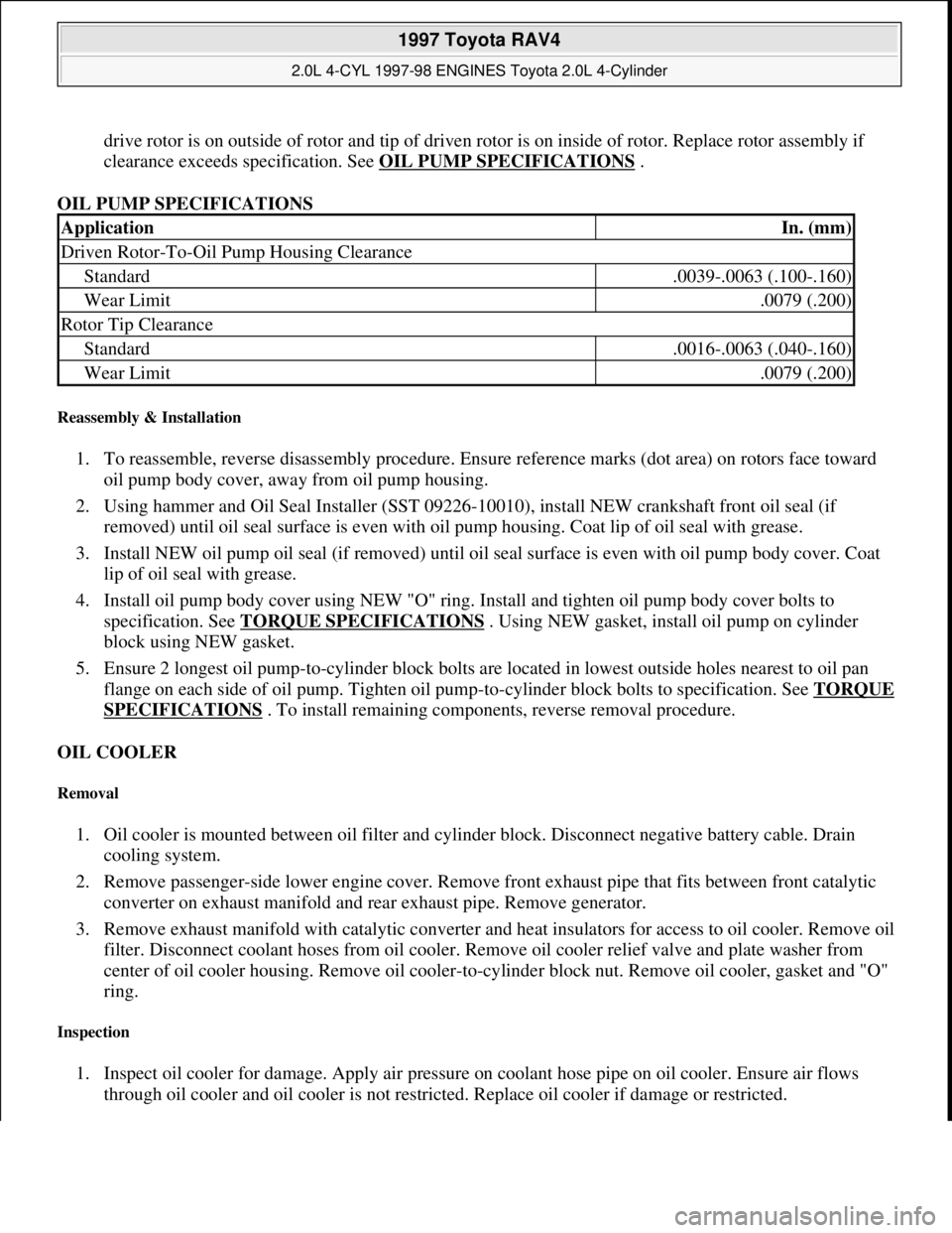
drive rotor is on outside of rotor and tip of driven rotor is on inside of rotor. Replace rotor assembly if
clearance exceeds specification. See OIL PUMP SPECIFICATIONS
.
OIL PUMP SPECIFICATIONS
Reassembly & Installation
1. To reassemble, reverse disassembly procedure. Ensure reference marks (dot area) on rotors face toward
oil pump body cover, away from oil pump housing.
2. Using hammer and Oil Seal Installer (SST 09226-10010), install NEW crankshaft front oil seal (if
removed) until oil seal surface is even with oil pump housing. Coat lip of oil seal with grease.
3. Install NEW oil pump oil seal (if removed) until oil seal surface is even with oil pump body cover. Coat
lip of oil seal with grease.
4. Install oil pump body cover using NEW "O" ring. Install and tighten oil pump body cover bolts to
specification. See TORQUE SPECIFICATIONS
. Using NEW gasket, install oil pump on cylinder
block using NEW gasket.
5. Ensure 2 longest oil pump-to-cylinder block bolts are located in lowest outside holes nearest to oil pan
flange on each side of oil pump. Tighten oil pump-to-cylinder block bolts to specification. See TORQUE
SPECIFICATIONS . To install remaining components, reverse removal procedure.
OIL COOLER
Removal
1. Oil cooler is mounted between oil filter and cylinder block. Disconnect negative battery cable. Drain
cooling system.
2. Remove passenger-side lower engine cover. Remove front exhaust pipe that fits between front catalytic
converter on exhaust manifold and rear exhaust pipe. Remove generator.
3. Remove exhaust manifold with catalytic converter and heat insulators for access to oil cooler. Remove oil
filter. Disconnect coolant hoses from oil cooler. Remove oil cooler relief valve and plate washer from
center of oil cooler housing. Remove oil cooler-to-cylinder block nut. Remove oil cooler, gasket and "O"
ring.
Inspection
1. Inspect oil cooler for damage. Apply air pressure on coolant hose pipe on oil cooler. Ensure air flows
through oil cooler and oil cooler is not restricted. Replace oil cooler if damage or restricted.
ApplicationIn. (mm)
Driven Rotor-To-Oil Pump Housing Clearance
Standard.0039-.0063 (.100-.160)
Wear Limit.0079 (.200)
Rotor Tip Clearance
Standard.0016-.0063 (.040-.160)
Wear Limit.0079 (.200)
1997 Toyota RAV4
2.0L 4-CYL 1997-98 ENGINES Toyota 2.0L 4-Cylinder
Microsoft
Sunday, November 22, 2009 10:23:31 AMPage 59 © 2005 Mitchell Repair Information Company, LLC.
Page 816 of 1632
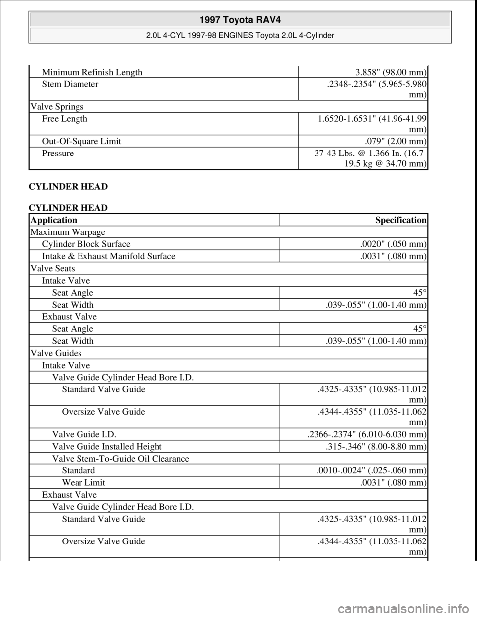
CYLINDER HEAD
CYLINDER HEAD
Minimum Refinish Length3.858" (98.00 mm)
Stem Diameter.2348-.2354" (5.965-5.980
mm)
Valve Springs
Free Length1.6520-1.6531" (41.96-41.99
mm)
Out-Of-Square Limit.079" (2.00 mm)
Pressure37-43 Lbs. @ 1.366 In. (16.7-
19.5 kg @ 34.70 mm)
ApplicationSpecification
Maximum Warpage
Cylinder Block Surface.0020" (.050 mm)
Intake & Exhaust Manifold Surface.0031" (.080 mm)
Valve Seats
Intake Valve
Seat Angle45°
Seat Width.039-.055" (1.00-1.40 mm)
Exhaust Valve
Seat Angle45°
Seat Width.039-.055" (1.00-1.40 mm)
Valve Guides
Intake Valve
Valve Guide Cylinder Head Bore I.D.
Standard Valve Guide.4325-.4335" (10.985-11.012
mm)
Oversize Valve Guide.4344-.4355" (11.035-11.062
mm)
Valve Guide I.D..2366-.2374" (6.010-6.030 mm)
Valve Guide Installed Height.315-.346" (8.00-8.80 mm)
Valve Stem-To-Guide Oil Clearance
Standard.0010-.0024" (.025-.060 mm)
Wear Limit.0031" (.080 mm)
Exhaust Valve
Valve Guide Cylinder Head Bore I.D.
Standard Valve Guide.4325-.4335" (10.985-11.012
mm)
Oversize Valve Guide.4344-.4355" (11.035-11.062
mm)
1997 Toyota RAV4
2.0L 4-CYL 1997-98 ENGINES Toyota 2.0L 4-Cylinder
Microsoft
Sunday, November 22, 2009 10:23:31 AMPage 68 © 2005 Mitchell Repair Information Company, LLC.
Page 817 of 1632
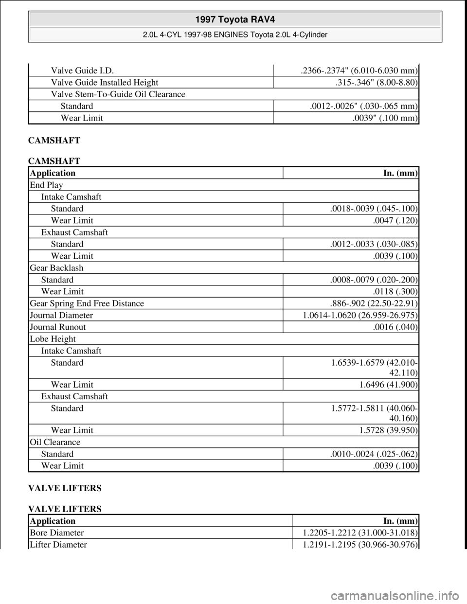
CAMSHAFT
CAMSHAFT
VALVE LIFTERS
VALVE LIFTERS
Valve Guide I.D..2366-.2374" (6.010-6.030 mm)
Valve Guide Installed Height.315-.346" (8.00-8.80)
Valve Stem-To-Guide Oil Clearance
Standard.0012-.0026" (.030-.065 mm)
Wear Limit.0039" (.100 mm)
ApplicationIn. (mm)
End Play
Intake Camshaft
Standard.0018-.0039 (.045-.100)
Wear Limit.0047 (.120)
Exhaust Camshaft
Standard.0012-.0033 (.030-.085)
Wear Limit.0039 (.100)
Gear Backlash
Standard.0008-.0079 (.020-.200)
Wear Limit.0118 (.300)
Gear Spring End Free Distance.886-.902 (22.50-22.91)
Journal Diameter1.0614-1.0620 (26.959-26.975)
Journal Runout.0016 (.040)
Lobe Height
Intake Camshaft
Standard1.6539-1.6579 (42.010-
42.110)
Wear Limit1.6496 (41.900)
Exhaust Camshaft
Standard1.5772-1.5811 (40.060-
40.160)
Wear Limit1.5728 (39.950)
Oil Clearance
Standard.0010-.0024 (.025-.062)
Wear Limit.0039 (.100)
ApplicationIn. (mm)
Bore Diameter1.2205-1.2212 (31.000-31.018)
Lifter Diameter1.2191-1.2195 (30.966-30.976)
1997 Toyota RAV4
2.0L 4-CYL 1997-98 ENGINES Toyota 2.0L 4-Cylinder
Microsoft
Sunday, November 22, 2009 10:23:31 AMPage 69 © 2005 Mitchell Repair Information Company, LLC.
Page 982 of 1632
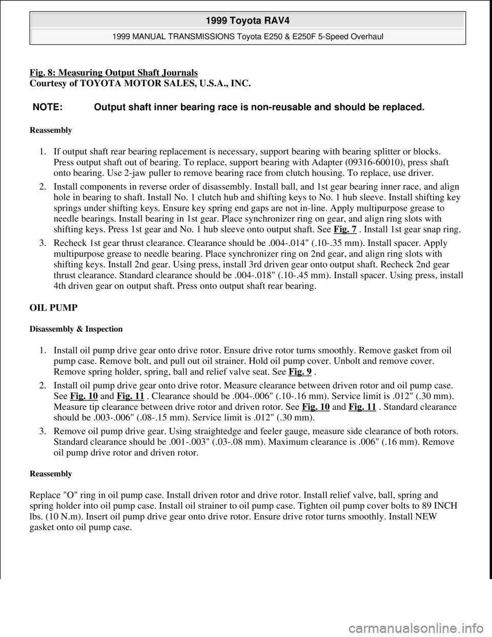
Fig. 8: Measuring Output Shaft Journals
Courtesy of TOYOTA MOTOR SALES, U.S.A., INC.
Reassembly
1. If output shaft rear bearing replacement is necessary, support bearing with bearing splitter or blocks.
Press output shaft out of bearing. To replace, support bearing with Adapter (09316-60010), press shaft
onto bearing. Use 2-jaw puller to remove bearing race from clutch housing. To replace, use driver.
2. Install components in reverse order of disassembly. Install ball, and 1st gear bearing inner race, and align
hole in bearing to shaft. Install No. 1 clutch hub and shifting keys to No. 1 hub sleeve. Install shifting key
springs under shifting keys. Ensure key spring end gaps are not in-line. Apply multipurpose grease to
needle bearings. Install bearing in 1st gear. Place synchronizer ring on gear, and align ring slots with
shifting keys. Press 1st gear and No. 1 hub sleeve onto output shaft. See Fig. 7
. Install 1st gear snap ring.
3. Recheck 1st gear thrust clearance. Clearance should be .004-.014" (.10-.35 mm). Install spacer. Apply
multipurpose grease to needle bearing. Place synchronizer ring on 2nd gear, and align ring slots with
shifting keys. Install 2nd gear. Using press, install 3rd driven gear onto output shaft. Recheck 2nd gear
thrust clearance. Standard clearance should be .004-.018" (.10-.45 mm). Install spacer. Using press, install
4th driven gear on output shaft. Press onto output shaft rear bearing.
OIL PUMP
Disassembly & Inspection
1. Install oil pump drive gear onto drive rotor. Ensure drive rotor turns smoothly. Remove gasket from oil
pump case. Remove bolt, and pull out oil strainer. Hold oil pump cover. Unbolt and remove cover.
Remove spring holder, spring, ball and relief valve seat. See Fig. 9
.
2. Install oil pump drive gear onto drive rotor. Measure clearance between driven rotor and oil pump case.
See Fig. 10
and Fig. 11 . Clearance should be .004-.006" (.10-.16 mm). Service limit is .012" (.30 mm).
Measure tip clearance between drive rotor and driven rotor. See Fig. 10
and Fig. 11 . Standard clearance
should be .003-.006" (.08-.15 mm). Service limit is .012" (.30 mm).
3. Remove oil pump drive gear. Using straightedge and feeler gauge, measure side clearance of both rotors.
Standard clearance should be .001-.003" (.03-.08 mm). Maximum clearance is .006" (.16 mm). Remove
oil pump drive rotor and driven rotor.
Reassembly
Replace "O" ring in oil pump case. Install driven rotor and drive rotor. Install relief valve, ball, spring and
spring holder into oil pump case. Install oil strainer to oil pump case. Tighten oil pump cover bolts to 89 INCH
lbs. (10 N.m). Insert oil pump drive gear onto drive rotor. Ensure drive rotor turns smoothly. Install NEW
gasket onto oil pump case. NOTE: Output shaft inner bearing race is non-reusable and should be replaced.
1999 Toyota RAV4
1999 MANUAL TRANSMISSIONS Toyota E250 & E250F 5-Speed Overhaul
Microsoft
Sunday, November 22, 2009 10:48:07 AMPage 12 © 2005 Mitchell Repair Information Company, LLC.
Page 1052 of 1632
1999 ENGINE PERFORMANCE
On-Vehicle Adjustments - 4-Cylinder
ENGINE MECHANICAL
Before performing any on-vehicle adjustments to fuel or ignition systems, ensure engine mechanical condition
is okay.
VALVE CLEARANCE
Camry, Camry Solara, Celica & RAV4
1. Disconnect spark plug wires from spark plugs and valve cover. Disconnect necessary hoses, control
cables and engine wiring clamps for removal of valve cover.
2. Disconnect engine wiring protector from rear of upper timing belt cover for access to valve cover if
necessary. Engine wiring protector is attached to bolts for upper timing belt cover. Remove engine wiring
protector from upper timing belt cover bolt on intake side of engine first, and then from upper timing belt
cover bolt on exhaust side of engine.
3. Note location of grommets between valve cover nuts and valve cover for installation reference. Grommets
should be installed in original location to prevent oil leakage. Remove valve cover nuts, grommets, valve
cover and gasket.
4. Rotate crankshaft clockwise (viewed from timing belt end of engine) until timing mark (groove) on
crankshaft pulley aligns with "0" mark on timing belt cover and cylinder No. 1 is at TDC on compression
stroke. Cylinder No. 1 is front cylinder at timing belt end of engine.
5. Ensure valve lifters on cylinder No. 1 are loose and valve lifters on cylinder No. 4 are tight. If valve
lifters are not as specified, rotate crankshaft clockwise one full revolution (360 degrees) and realign
crankshaft pulley timing mark (groove) with "0" mark on timing belt cover.
6. With cylinder No. 1 at TDC on compression stroke, use feeler gauge to check valve clearance between
valve lifter and camshaft on specified valves. Perform STEP 1. See Fig. 1
. Record valve clearance.
7. To check remaining valves, rotate crankshaft clockwise one full revolution (360 degrees) and realign
crankshaft pulley timing mark (groove) with "0" mark on timing belt cover. Using feeler gauge, measure
valve clearance on specified valves. Perform STEP 2. See Fig. 1
. Record valve clearance.
8. Ensure valve clearance is within specification. See VALVE CLEARANCE SPECIFICATIONS
(CAMRY, CAMRY SOLARA, CELICA & RAV4)table. NOTE: Check and adjust valve clearance with engine cold.
1999 Toyota RAV4
1999 ENGINE PERFORMANCE On-Vehicle Adjustments - 4-Cylinder
1999 Toyota RAV4
1999 ENGINE PERFORMANCE On-Vehicle Adjustments - 4-Cylinder
Microsoft
Sunday, November 22, 2009 10:25:31 AMPage 1 © 2005 Mitchell Repair Information Company, LLC.
Microsoft
Sunday, November 22, 2009 10:25:35 AMPage 1 © 2005 Mitchell Repair Information Company, LLC.
Page 1053 of 1632
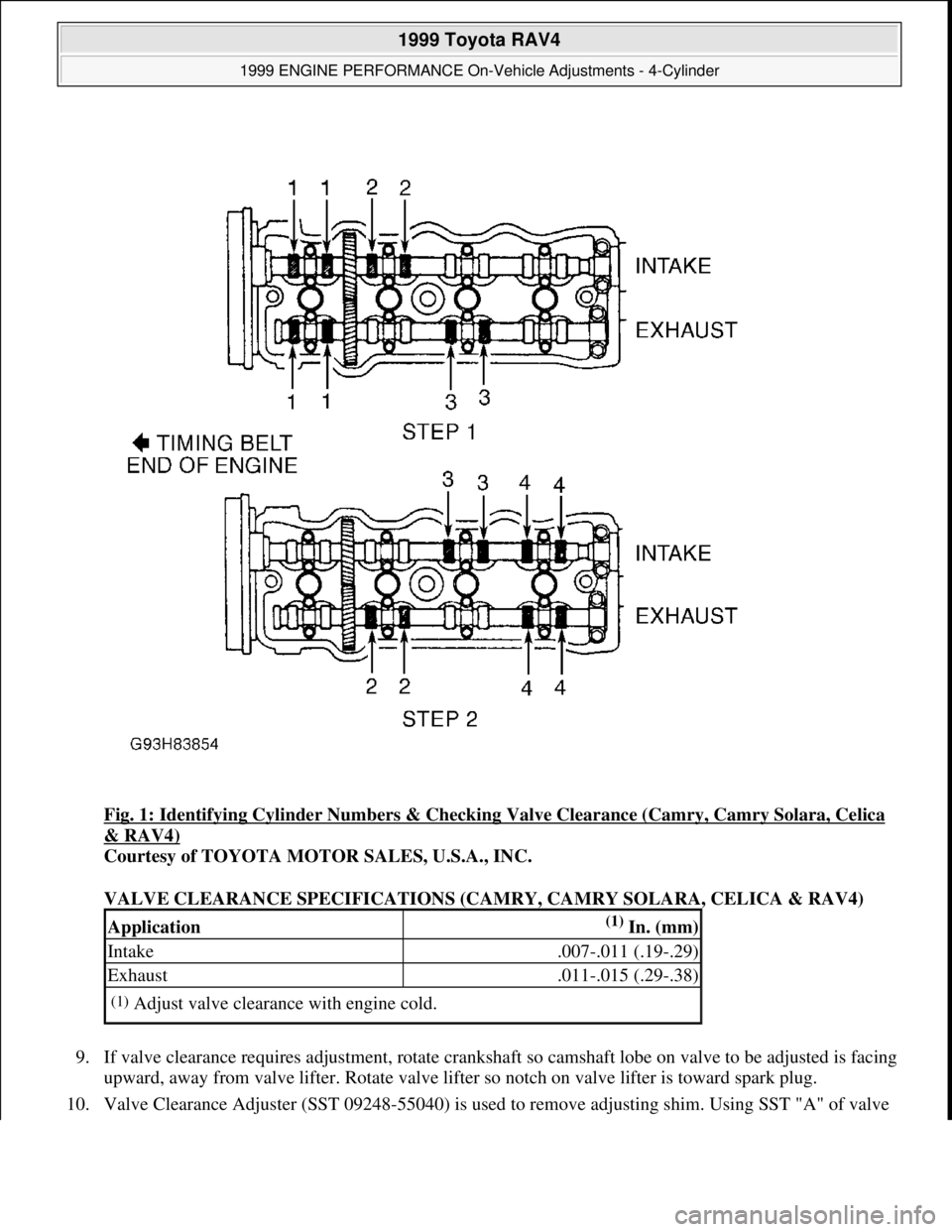
Fig. 1: Identifying Cylinder Numbers & Checking Valve Clearance (Camry, Camry Solara, Celica
& RAV4)
Courtesy of TOYOTA MOTOR SALES, U.S.A., INC.
VALVE CLEARANCE SPECIFICATIONS (CAMRY, CAMRY SOLARA, CELICA & RAV4)
9. If valve clearance requires adjustment, rotate crankshaft so camshaft lobe on valve to be adjusted is facing
upward, away from valve lifter. Rotate valve lifter so notch on valve lifter is toward spark plug.
10. Valve Clearance Ad
juster (SST 09248-55040) is used to remove adjusting shim. Using SST "A" of valve
Application(1) In. (mm)
Intake.007-.011 (.19-.29)
Exhaust.011-.015 (.29-.38)
(1)Adjust valve clearance with engine cold.
1999 Toyota RAV4
1999 ENGINE PERFORMANCE On-Vehicle Adjustments - 4-Cylinder
Microsoft
Sunday, November 22, 2009 10:25:31 AMPage 2 © 2005 Mitchell Repair Information Company, LLC.
Page 1054 of 1632
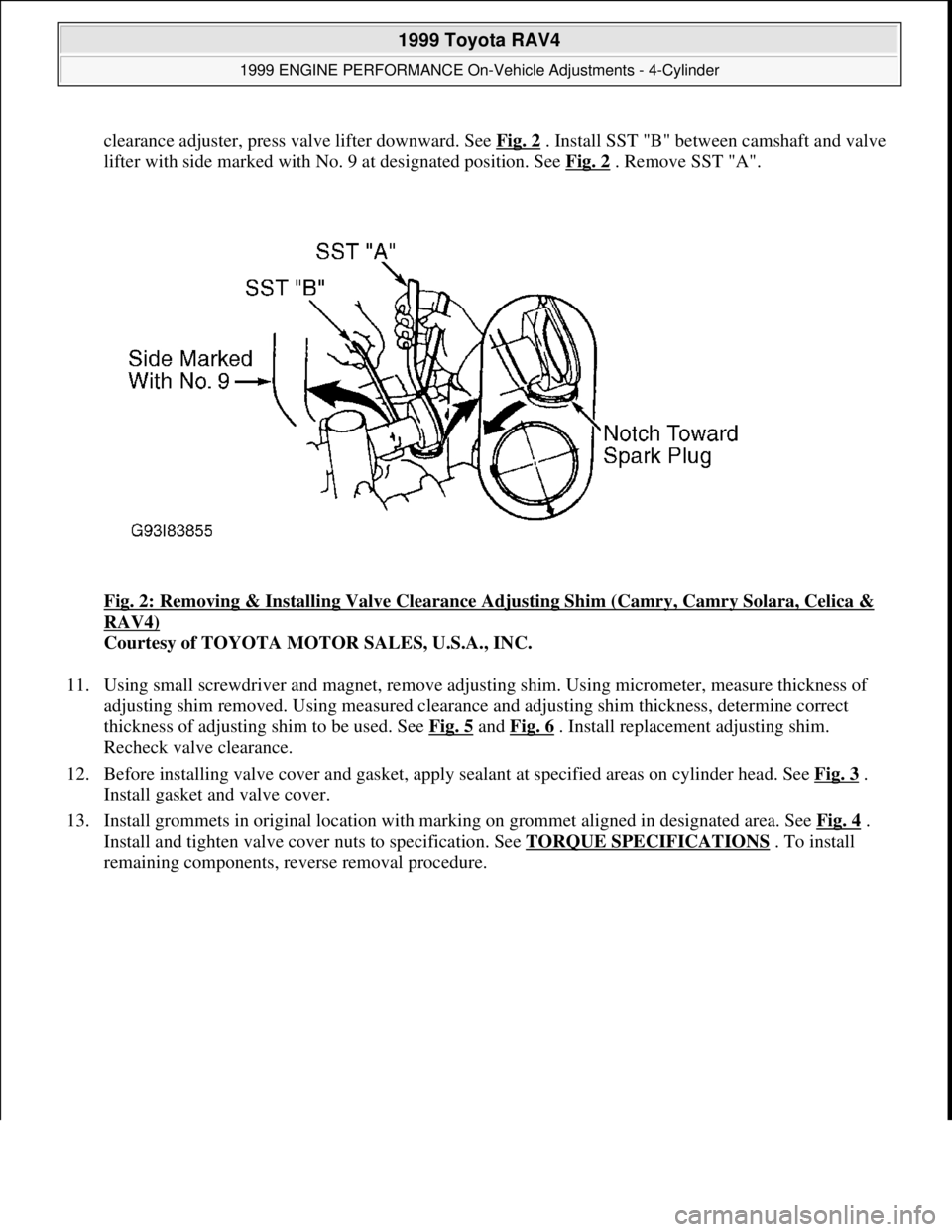
clearance adjuster, press valve lifter downward. See Fig. 2. Install SST "B" between camshaft and valve
lifter with side marked with No. 9 at designated position. See Fig. 2
. Remove SST "A".
Fig. 2: Removing & Installing Valve Clearance Adjusting Shim (Camry, Camry Solara, Celica &
RAV4)
Courtesy of TOYOTA MOTOR SALES, U.S.A., INC.
11. Using small screwdriver and magnet, remove adjusting shim. Using micrometer, measure thickness of
adjusting shim removed. Using measured clearance and adjusting shim thickness, determine correct
thickness of adjusting shim to be used. See Fig. 5
and Fig. 6 . Install replacement adjusting shim.
Recheck valve clearance.
12. Before installing valve cover and gasket, apply sealant at specified areas on cylinder head. See Fig. 3
.
Install gasket and valve cover.
13. Install grommets in original location with marking on grommet aligned in designated area. See Fig. 4
.
Install and tighten valve cover nuts to specification. See TORQUE SPECIFICATIONS
. To install
remaining components, reverse removal procedure.
1999 Toyota RAV4
1999 ENGINE PERFORMANCE On-Vehicle Adjustments - 4-Cylinder
Microsoft
Sunday, November 22, 2009 10:25:31 AMPage 3 © 2005 Mitchell Repair Information Company, LLC.
Page 1061 of 1632
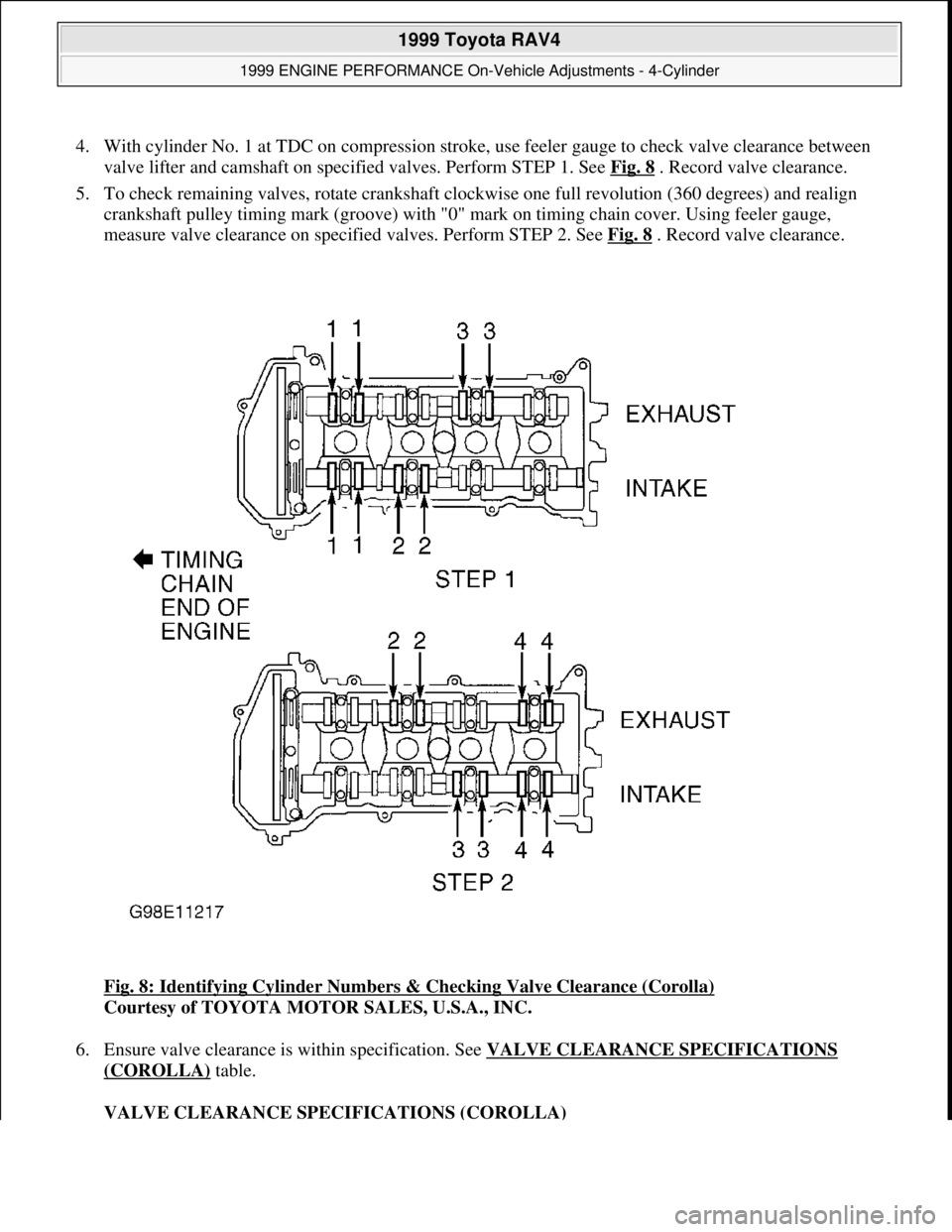
4. With cylinder No. 1 at TDC on compression stroke, use feeler gauge to check valve clearance between
valve lifter and camshaft on specified valves. Perform STEP 1. See Fig. 8
. Record valve clearance.
5. To check remaining valves, rotate crankshaft clockwise one full revolution (360 degrees) and realign
crankshaft pulley timing mark (groove) with "0" mark on timing chain cover. Using feeler gauge,
measure valve clearance on specified valves. Perform STEP 2. See Fig. 8
. Record valve clearance.
Fig. 8: Identifying Cylinder Numbers & Checking Valve Clearance (Corolla)
Courtesy of TOYOTA MOTOR SALES, U.S.A., INC.
6. Ensure valve clearance is within specification. See VALVE CLEARANCE SPECIFICATIONS
(COROLLA) table.
VALVE CLEARANCE SPECIFICATIONS (COROLLA)
1999 Toyota RAV4
1999 ENGINE PERFORMANCE On-Vehicle Adjustments - 4-Cylinder
Microsoft
Sunday, November 22, 2009 10:25:31 AMPage 10 © 2005 Mitchell Repair Information Company, LLC.
Page 1062 of 1632
7. If valve clearance requires adjustment, camshafts must be removed for access to valve lifters. Different
thickness valve lifters are used. Manufacturer recommends placing reference mark on timing chain and
camshaft sprockets, removing timing chain tensioner and then removing camshaft sprockets and
camshafts for access to valve lifter while supporting timing chain. To remove camshafts, see appropriate
article in ENGINES.
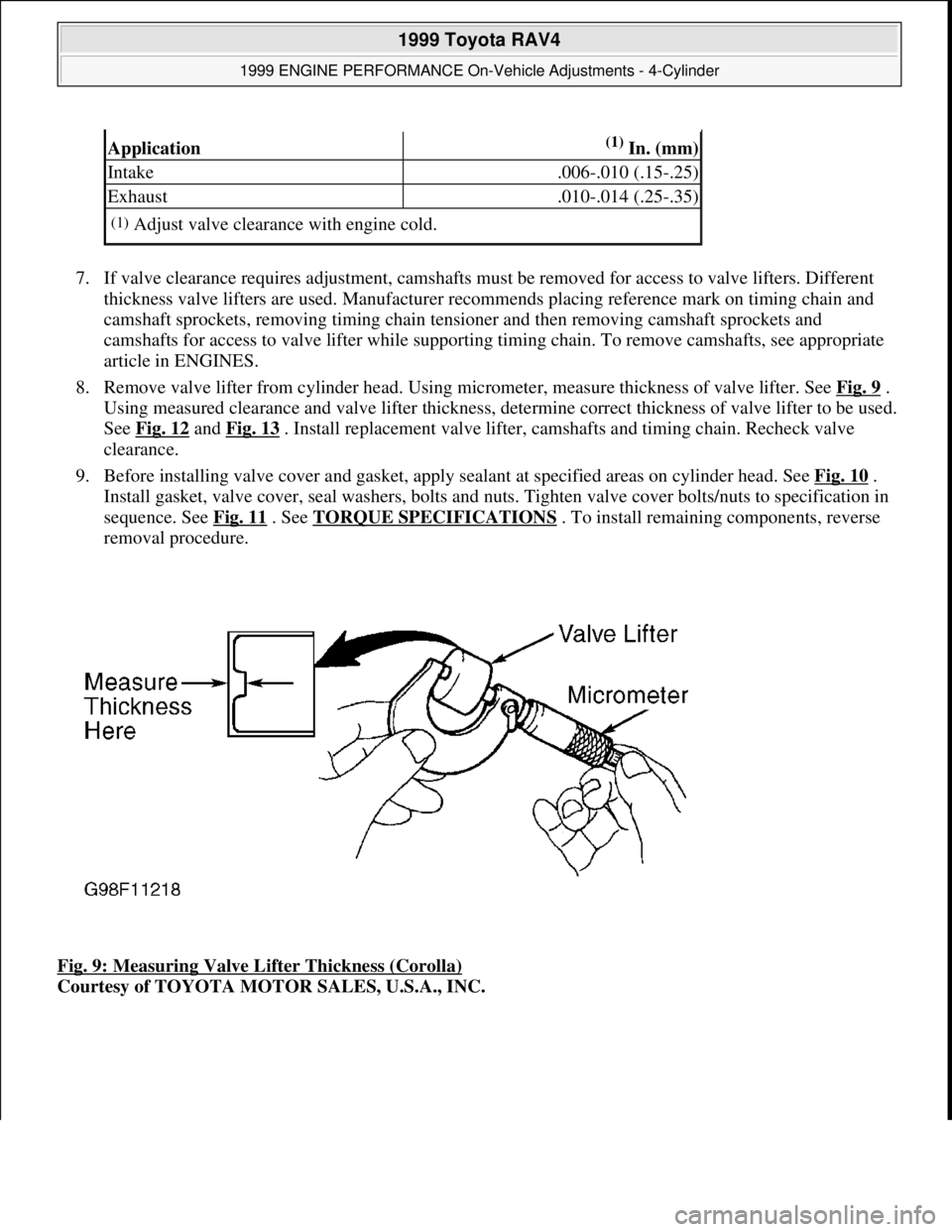
8. Remove valve lifter from cylinder head. Using micrometer, measure thickness of valve lifter. See Fig. 9
.
Using measured clearance and valve lifter thickness, determine correct thickness of valve lifter to be used.
See Fig. 12
and Fig. 13 . Install replacement valve lifter, camshafts and timing chain. Recheck valve
clearance.
9. Before installing valve cover and gasket, apply sealant at specified areas on cylinder head. See Fig. 10
.
Install gasket, valve cover, seal washers, bolts and nuts. Tighten valve cover bolts/nuts to specification in
sequence. See Fig. 11
. See TORQUE SPECIFICATIONS . To install remaining components, reverse
removal procedure.
Fig. 9: Measuring Valve Lifter Thickness (Corolla)
Courtesy of TOYOTA MOTOR SALES, U.S.A., INC.
Application(1) In. (mm)
Intake.006-.010 (.15-.25)
Exhaust.010-.014 (.25-.35)
(1)Adjust valve clearance with engine cold.
1999 Toyota RAV4
1999 ENGINE PERFORMANCE On-Vehicle Adjustments - 4-Cylinder
Microsoft
Sunday, November 22, 2009 10:25:31 AMPage 11 © 2005 Mitchell Repair Information Company, LLC.