valve clearance TOYOTA RAV4 1996 Service Service Manual
[x] Cancel search | Manufacturer: TOYOTA, Model Year: 1996, Model line: RAV4, Model: TOYOTA RAV4 1996Pages: 1632, PDF Size: 41.64 MB
Page 1067 of 1632
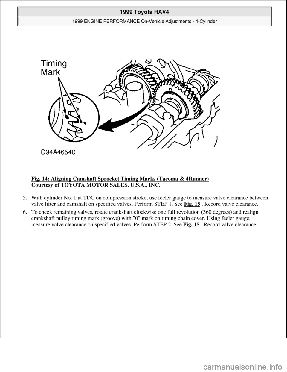
Fig. 14: Aligning Camshaft Sprocket Timing Marks (Tacoma & 4Runner)
Courtesy of TOYOTA MOTOR SALES, U.S.A., INC.
5. With cylinder No. 1 at TDC on compression stroke, use feeler gauge to measure valve clearance between
valve lifter and camshaft on specified valves. Perform STEP 1. See Fig. 15
. Record valve clearance.
6. To check remaining valves, rotate crankshaft clockwise one full revolution (360 degrees) and realign
crankshaft pulley timing mark (groove) with "0" mark on timing chain cover. Using feeler gauge,
measure valve clearance on specified valves. Perform STEP 2. See Fig. 15
. Record valve clearance.
1999 Toyota RAV4
1999 ENGINE PERFORMANCE On-Vehicle Adjustments - 4-Cylinder
Microsoft
Sunday, November 22, 2009 10:25:31 AMPage 16 © 2005 Mitchell Repair Information Company, LLC.
Page 1068 of 1632
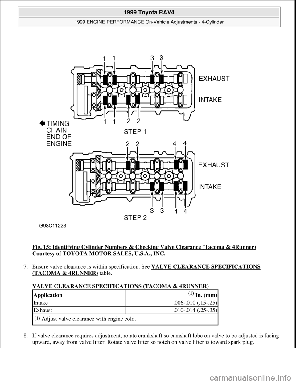
Fig. 15: Identifying Cylinder Numbers & Checking Valve Clearance (Tacoma & 4Runner)
Courtesy of TOYOTA MOTOR SALES, U.S.A., INC.
7. Ensure valve clearance is within specification. See VALVE CLEARANCE SPECIFICATIONS
(TACOMA & 4RUNNER) table.
VALVE CLEARANCE SPECIFICATIONS (TACOMA & 4RUNNER)
8. If valve clearance requires adjustment, rotate crankshaft so camshaft lobe on valve to be adjusted is facing
upward, awa
y from valve lifter. Rotate valve lifter so notch on valve lifter is toward spark plug.
Application(1) In. (mm)
Intake.006-.010 (.15-.25)
Exhaust.010-.014 (.25-.35)
(1)Adjust valve clearance with engine cold.
1999 Toyota RAV4
1999 ENGINE PERFORMANCE On-Vehicle Adjustments - 4-Cylinder
Microsoft
Sunday, November 22, 2009 10:25:31 AMPage 17 © 2005 Mitchell Repair Information Company, LLC.
Page 1069 of 1632
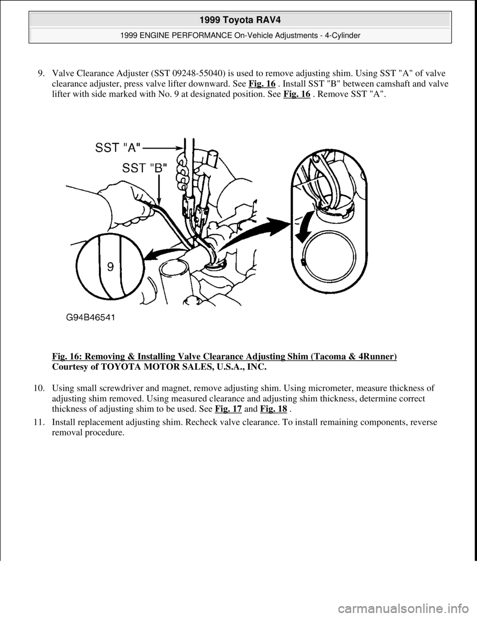
9. Valve Clearance Adjuster (SST 09248-55040) is used to remove adjusting shim. Using SST "A" of valve
clearance adjuster, press valve lifter downward. See Fig. 16
. Install SST "B" between camshaft and valve
lifter with side marked with No. 9 at designated position. See Fig. 16
. Remove SST "A".
Fig. 16: Removing & Installing Valve Clearance Adjusting Shim (Tacoma & 4Runner)
Courtesy of TOYOTA MOTOR SALES, U.S.A., INC.
10. Using small screwdriver and magnet, remove adjusting shim. Using micrometer, measure thickness of
adjusting shim removed. Using measured clearance and adjusting shim thickness, determine correct
thickness of adjusting shim to be used. See Fig. 17
and Fig. 18 .
11. Install replacement adjusting shim. Recheck valve clearance. To install remaining components, reverse
removal procedure.
1999 Toyota RAV4
1999 ENGINE PERFORMANCE On-Vehicle Adjustments - 4-Cylinder
Microsoft
Sunday, November 22, 2009 10:25:31 AMPage 18 © 2005 Mitchell Repair Information Company, LLC.
Page 1087 of 1632
1. Start engine and warm engine to normal operating temperature. Shut engine off. Remove cover (if
equipped) and connect scan tool to data link connector No. 3. See Fig. 19
-Fig. 25 . Scan tool is used to
read engine RPM.
2. Apply parking brake. Place transmission/transaxle in Neutral. Start engine and maintain engine at 2500
RPM for 90 seconds and then allow engine to idle. Ensure idle speed is within specification. See IDLE
SPEED SPECIFICATIONS table.
3. If idle speed is not within specification, check air intake system, Idle Air Control (IAC) valve, wiring and
Engine Control Module (ECM). See IDLE CONTROL SYSTEM in SYSTEM & COMPONENT
TESTING - 4-CYLINDER article. Shut engine off. Remove scan tool.
IDLE SPEED SPECIFICATIONS
(1)
THROTTLE POSITION SENSOR
4-CYLINDER THROTTLE POSITION SENSOR
Camry & Camry Solara
1. Manufacturer does not list procedure for Throttle Position (TP) sensor adjustment. Only information
available is for checking resistance of TP sensor.
2. Disconnect electrical connector from TP sensor. Note electrical terminals on TP sensor. See Fig. 32
.
Apply vacuum to throttle opener.
3. Using ohmmeter, check resistance between specified terminals in relation to throttle position. See
THROTTLE POSITION SENSOR RESISTANCE
table. Replace components as necessary if
resistance is not within specification.
Celica
1. Disconnect electrical connector from Throttle Position (TP) sensor. Loosen TP sensor mounting screws.
Connect ohmmeter between terminals IDL and E2. See Fig. 33
.
2. Apply vacuum to throttle opener. To set initial clearance, insert .024" (.60 mm) feeler gauge between
throttle stop screw and throttle lever.
3. Gradually rotate TP sensor clockwise until ohmmeter deflects. Tighten TP sensor mounting screws.
Remove feeler
gauge. Reinsert a .020" (.50 mm) feeler gauge. Continuity should exist between terminals
ApplicationRPM
Camry, Camry Solara, Celica &
Corolla650-750
RAV4700-800
Tacoma & 4Runner650-750
(1)Check with engine at normal operating temperature, transmission/transaxle
in Neutral, parking brake applied, air cleaner and all vacuum hoses
installed, electronic fuel injection system wiring connectors properly
installed, ignition timing properly set, electric cooling fan off (if
equipped), and A/C and all accessories off.
1999 Toyota RAV4
1999 ENGINE PERFORMANCE On-Vehicle Adjustments - 4-Cylinder
Microsoft
Sunday, November 22, 2009 10:25:31 AMPage 36 © 2005 Mitchell Repair Information Company, LLC.
Page 1104 of 1632
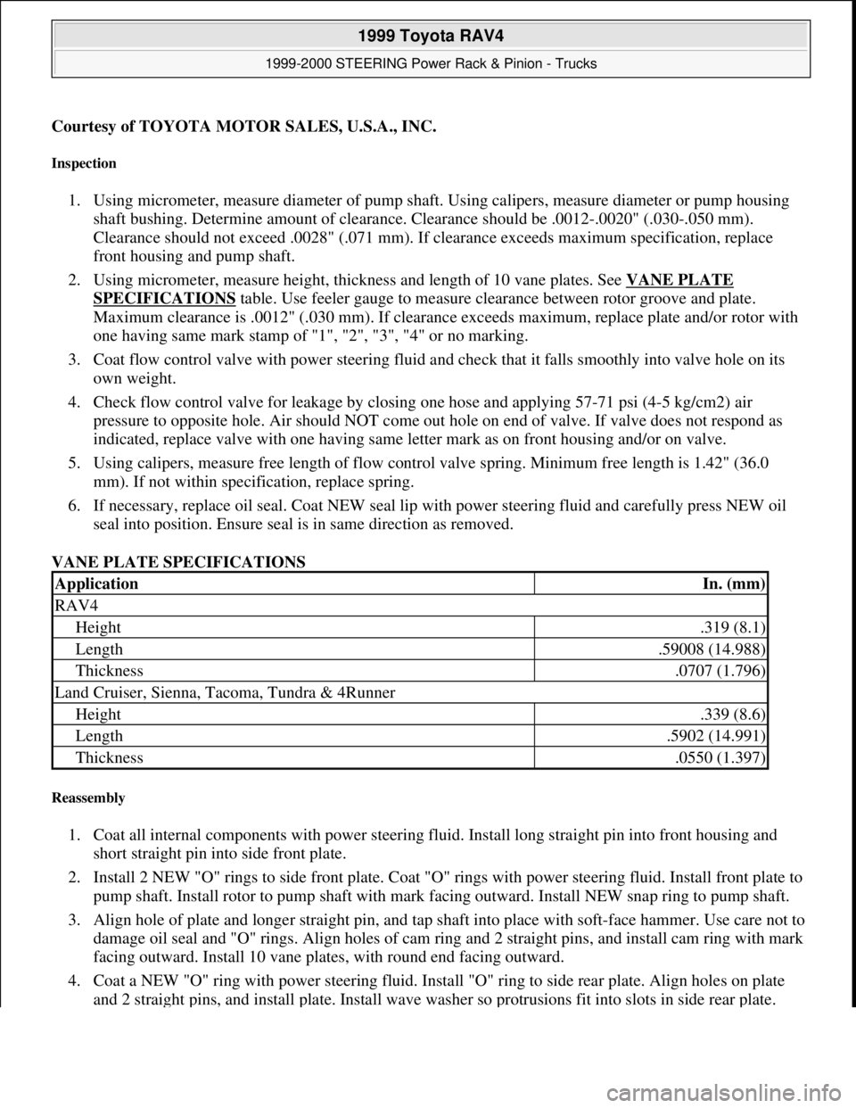
Courtesy of TOYOTA MOTOR SALES, U.S.A., INC.
Inspection
1. Using micrometer, measure diameter of pump shaft. Using calipers, measure diameter or pump housing
shaft bushing. Determine amount of clearance. Clearance should be .0012-.0020" (.030-.050 mm).
Clearance should not exceed .0028" (.071 mm). If clearance exceeds maximum specification, replace
front housing and pump shaft.
2. Using micrometer, measure height, thickness and length of 10 vane plates. See VANE PLATE
SPECIFICATIONS table. Use feeler gauge to measure clearance between rotor groove and plate.
Maximum clearance is .0012" (.030 mm). If clearance exceeds maximum, replace plate and/or rotor with
one having same mark stamp of "1", "2", "3", "4" or no marking.
3. Coat flow control valve with power steering fluid and check that it falls smoothly into valve hole on its
own weight.
4. Check flow control valve for leakage by closing one hose and applying 57-71 psi (4-5 kg/cm2) air
pressure to opposite hole. Air should NOT come out hole on end of valve. If valve does not respond as
indicated, replace valve with one having same letter mark as on front housing and/or on valve.
5. Using calipers, measure free length of flow control valve spring. Minimum free length is 1.42" (36.0
mm). If not within specification, replace spring.
6. If necessary, replace oil seal. Coat NEW seal lip with power steering fluid and carefully press NEW oil
seal into position. Ensure seal is in same direction as removed.
VANE PLATE SPECIFICATIONS
Reassembly
1. Coat all internal components with power steering fluid. Install long straight pin into front housing and
short straight pin into side front plate.
2. Install 2 NEW "O" rings to side front plate. Coat "O" rings with power steering fluid. Install front plate to
pump shaft. Install rotor to pump shaft with mark facing outward. Install NEW snap ring to pump shaft.
3. Align hole of plate and longer straight pin, and tap shaft into place with soft-face hammer. Use care not to
damage oil seal and "O" rings. Align holes of cam ring and 2 straight pins, and install cam ring with mark
facing outward. Install 10 vane plates, with round end facing outward.
4. Coat a NEW "O" ring with power steering fluid. Install "O" ring to side rear plate. Align holes on plate
and 2 straight pins, and install plate. Install wave washer so protrusions fit into slots in side rear plate.
ApplicationIn. (mm)
RAV4
Height.319 (8.1)
Length.59008 (14.988)
Thickness.0707 (1.796)
Land Cruiser, Sienna, Tacoma, Tundra & 4Runner
Height.339 (8.6)
Length.5902 (14.991)
Thickness.0550 (1.397)
1999 Toyota RAV4
1999-2000 STEERING Power Rack & Pinion - Trucks
Microsoft
Sunday, November 22, 2009 10:35:46 AMPage 11 © 2005 Mitchell Repair Information Company, LLC.
Page 1107 of 1632
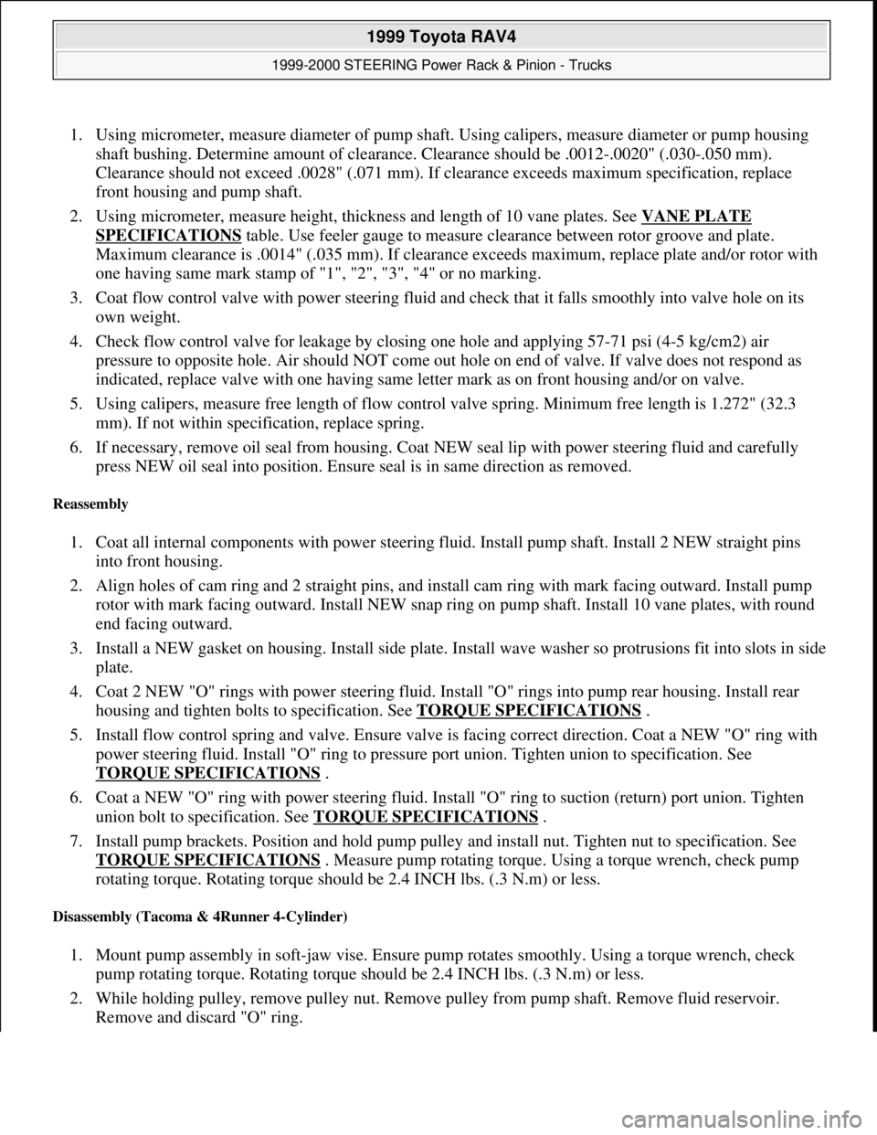
1. Using micrometer, measure diameter of pump shaft. Using calipers, measure diameter or pump housing
shaft bushing. Determine amount of clearance. Clearance should be .0012-.0020" (.030-.050 mm).
Clearance should not exceed .0028" (.071 mm). If clearance exceeds maximum specification, replace
front housing and pump shaft.
2. Using micrometer, measure height, thickness and length of 10 vane plates. See VANE PLATE
SPECIFICATIONS table. Use feeler gauge to measure clearance between rotor groove and plate.
Maximum clearance is .0014" (.035 mm). If clearance exceeds maximum, replace plate and/or rotor with
one having same mark stamp of "1", "2", "3", "4" or no marking.
3. Coat flow control valve with power steering fluid and check that it falls smoothly into valve hole on its
own weight.
4. Check flow control valve for leakage by closing one hole and applying 57-71 psi (4-5 kg/cm2) air
pressure to opposite hole. Air should NOT come out hole on end of valve. If valve does not respond as
indicated, replace valve with one having same letter mark as on front housing and/or on valve.
5. Using calipers, measure free length of flow control valve spring. Minimum free length is 1.272" (32.3
mm). If not within specification, replace spring.
6. If necessary, remove oil seal from housing. Coat NEW seal lip with power steering fluid and carefully
press NEW oil seal into position. Ensure seal is in same direction as removed.
Reassembly
1. Coat all internal components with power steering fluid. Install pump shaft. Install 2 NEW straight pins
into front housing.
2. Align holes of cam ring and 2 straight pins, and install cam ring with mark facing outward. Install pump
rotor with mark facing outward. Install NEW snap ring on pump shaft. Install 10 vane plates, with round
end facing outward.
3. Install a NEW gasket on housing. Install side plate. Install wave washer so protrusions fit into slots in side
plate.
4. Coat 2 NEW "O" rings with power steering fluid. Install "O" rings into pump rear housing. Install rear
housing and tighten bolts to specification. See TORQUE SPECIFICATIONS
.
5. Install flow control spring and valve. Ensure valve is facing correct direction. Coat a NEW "O" ring with
power steering fluid. Install "O" ring to pressure port union. Tighten union to specification. See
TORQUE SPECIFICATIONS
.
6. Coat a NEW "O" ring with power steering fluid. Install "O" ring to suction (return) port union. Tighten
union bolt to specification. See TORQUE SPECIFICATIONS
.
7. Install pump brackets. Position and hold pump pulley and install nut. Tighten nut to specification. See
TORQUE SPECIFICATIONS
. Measure pump rotating torque. Using a torque wrench, check pump
rotating torque. Rotating torque should be 2.4 INCH lbs. (.3 N.m) or less.
Disassembly (Tacoma & 4Runner 4-Cylinder)
1. Mount pump assembly in soft-jaw vise. Ensure pump rotates smoothly. Using a torque wrench, check
pump rotating torque. Rotating torque should be 2.4 INCH lbs. (.3 N.m) or less.
2. While holding pulley, remove pulley nut. Remove pulley from pump shaft. Remove fluid reservoir.
Remove and discard "O" ring.
1999 Toyota RAV4
1999-2000 STEERING Power Rack & Pinion - Trucks
Microsoft
Sunday, November 22, 2009 10:35:46 AMPage 14 © 2005 Mitchell Repair Information Company, LLC.
Page 1110 of 1632
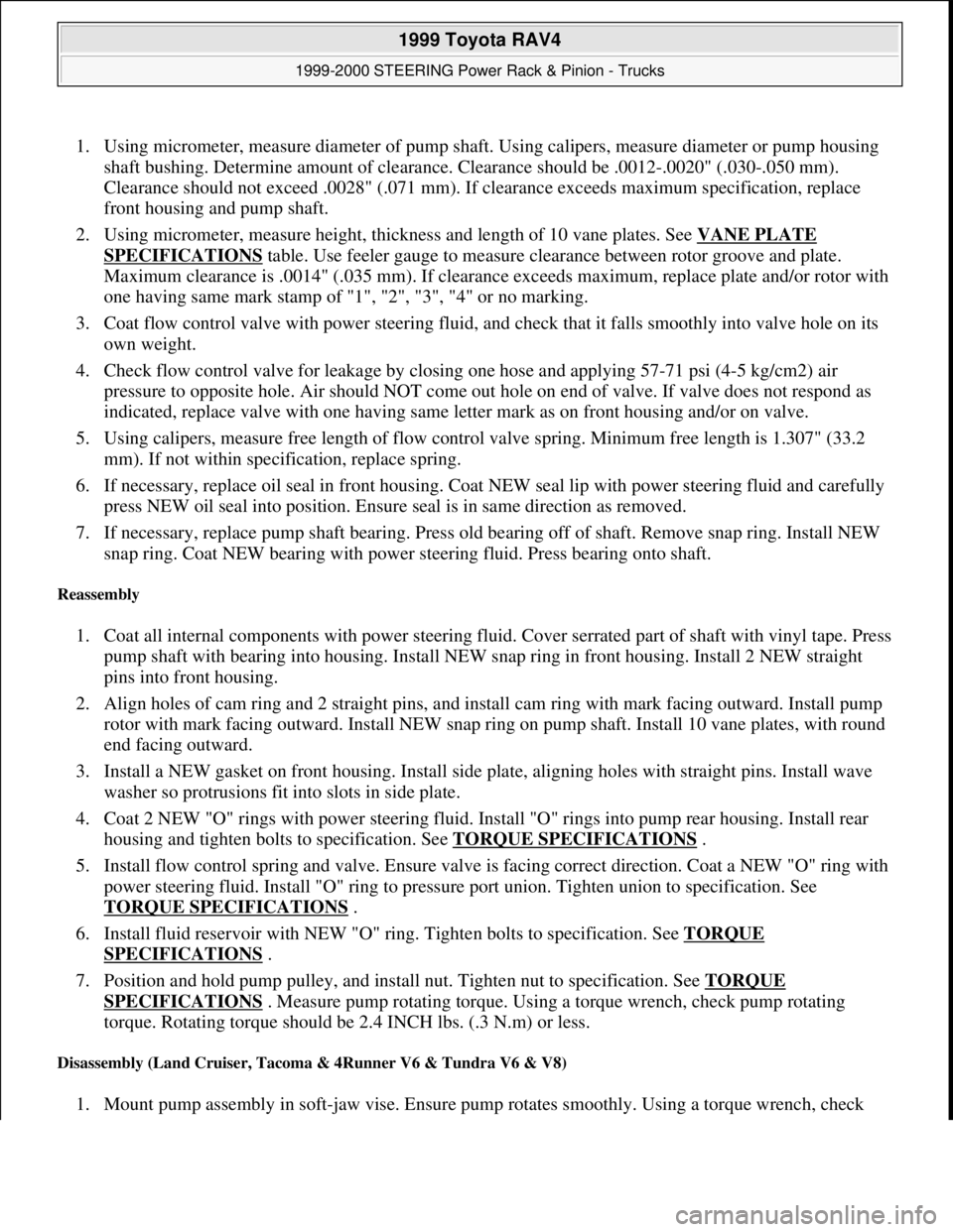
1. Using micrometer, measure diameter of pump shaft. Using calipers, measure diameter or pump housing
shaft bushing. Determine amount of clearance. Clearance should be .0012-.0020" (.030-.050 mm).
Clearance should not exceed .0028" (.071 mm). If clearance exceeds maximum specification, replace
front housing and pump shaft.
2. Using micrometer, measure height, thickness and length of 10 vane plates. See VANE PLATE
SPECIFICATIONS table. Use feeler gauge to measure clearance between rotor groove and plate.
Maximum clearance is .0014" (.035 mm). If clearance exceeds maximum, replace plate and/or rotor with
one having same mark stamp of "1", "2", "3", "4" or no marking.
3. Coat flow control valve with power steering fluid, and check that it falls smoothly into valve hole on its
own weight.
4. Check flow control valve for leakage by closing one hose and applying 57-71 psi (4-5 kg/cm2) air
pressure to opposite hole. Air should NOT come out hole on end of valve. If valve does not respond as
indicated, replace valve with one having same letter mark as on front housing and/or on valve.
5. Using calipers, measure free length of flow control valve spring. Minimum free length is 1.307" (33.2
mm). If not within specification, replace spring.
6. If necessary, replace oil seal in front housing. Coat NEW seal lip with power steering fluid and carefully
press NEW oil seal into position. Ensure seal is in same direction as removed.
7. If necessary, replace pump shaft bearing. Press old bearing off of shaft. Remove snap ring. Install NEW
snap ring. Coat NEW bearing with power steering fluid. Press bearing onto shaft.
Reassembly
1. Coat all internal components with power steering fluid. Cover serrated part of shaft with vinyl tape. Press
pump shaft with bearing into housing. Install NEW snap ring in front housing. Install 2 NEW straight
pins into front housing.
2. Align holes of cam ring and 2 straight pins, and install cam ring with mark facing outward. Install pump
rotor with mark facing outward. Install NEW snap ring on pump shaft. Install 10 vane plates, with round
end facing outward.
3. Install a NEW gasket on front housing. Install side plate, aligning holes with straight pins. Install wave
washer so protrusions fit into slots in side plate.
4. Coat 2 NEW "O" rings with power steering fluid. Install "O" rings into pump rear housing. Install rear
housing and tighten bolts to specification. See TORQUE SPECIFICATIONS
.
5. Install flow control spring and valve. Ensure valve is facing correct direction. Coat a NEW "O" ring with
power steering fluid. Install "O" ring to pressure port union. Tighten union to specification. See
TORQUE SPECIFICATIONS
.
6. Install fluid reservoir with NEW "O" ring. Tighten bolts to specification. See TORQUE
SPECIFICATIONS .
7. Position and hold pump pulley, and install nut. Tighten nut to specification. See TORQUE
SPECIFICATIONS . Measure pump rotating torque. Using a torque wrench, check pump rotating
torque. Rotating torque should be 2.4 INCH lbs. (.3 N.m) or less.
Disassembly (Land Cruiser, Tacoma & 4Runner V6 & Tundra V6 & V8)
1. Mount pump assembly in soft-jaw vise. Ensure pump rotates smoothly. Using a torque wrench, check
1999 Toyota RAV4
1999-2000 STEERING Power Rack & Pinion - Trucks
Microsoft
Sunday, November 22, 2009 10:35:47 AMPage 17 © 2005 Mitchell Repair Information Company, LLC.
Page 1113 of 1632
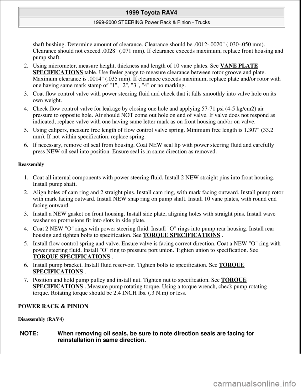
shaft bushing. Determine amount of clearance. Clearance should be .0012-.0020" (.030-.050 mm).
Clearance should not exceed .0028" (.071 mm). If clearance exceeds maximum, replace front housing and
pump shaft.
2. Using micrometer, measure height, thickness and length of 10 vane plates. See VANE PLATE
SPECIFICATIONS table. Use feeler gauge to measure clearance between rotor groove and plate.
Maximum clearance is .0014" (.035 mm). If clearance exceeds maximum, replace plate and/or rotor with
one having same mark stamp of "1", "2", "3", "4" or no marking.
3. Coat flow control valve with power steering fluid and check that it falls smoothly into valve hole on its
own weight.
4. Check flow control valve for leakage by closing one hole and applying 57-71 psi (4-5 kg/cm2) air
pressure to opposite hole. Air should NOT come out hole on end of valve. If valve does not respond as
indicated, replace valve with one having same letter mark as on front housing and/or on valve.
5. Using calipers, measure free length of flow control valve spring. Minimum free length is 1.307" (33.2
mm). If not within specification, replace spring.
6. If necessary, remove oil seal from housing. Coat NEW seal lip with power steering fluid and carefully
press NEW oil seal into position. Ensure seal is in same direction as removed.
Reassembly
1. Coat all internal components with power steering fluid. Install 2 NEW straight pins into front housing.
Install pump shaft.
2. Align holes of cam ring and 2 straight pins. Install cam ring, with mark facing outward. Install pump rotor
with mark facing outward. Install NEW snap ring on pump shaft. Install 10 vane plates, with round end
facing outward.
3. Install a NEW gasket on front housing. Install side plate, aligning holes with straight pins. Install wave
washer so protrusions fit into slots in side plate.
4. Coat 2 NEW "O" rings with power steering fluid. Install "O" rings into pump rear housing. Install rear
housing and tighten bolts to specification. See TORQUE SPECIFICATIONS
.
5. Install flow control spring and valve. Ensure valve is facing correct direction. Coat a NEW "O" ring with
power steering fluid. Install "O" ring to pressure port union. Tighten union to specification. See
TORQUE SPECIFICATIONS
.
6. Install pump bracket. Install fluid reservoir. Tighten bolts to specification. See TORQUE
SPECIFICATIONS .
7. Position and hold pump pulley and install nut. Tighten nut to specification. See TORQUE
SPECIFICATIONS . Measure pump rotating torque. Using a torque wrench, check pump rotating
torque. Rotating torque should be 2.4 INCH lbs. (.3 N.m) or less.
POWER RACK & PINION
Disassembly (RAV4)
NOTE: When removing oil seals, be sure to note direction seals are facing for
reinstallation in same direction.
1999 Toyota RAV4
1999-2000 STEERING Power Rack & Pinion - Trucks
Microsoft
Sunday, November 22, 2009 10:35:47 AMPage 20 © 2005 Mitchell Repair Information Company, LLC.
Page 1126 of 1632
15. Ensure steering rack hole (next to rack end) is not clogged with grease. Clean as necessary. Install boots
and clamps. Pinch clamps until there is .08" (2.0 mm), or less, clearance between clamp ends.
16. Screw tie rod end lock nut onto tie rod until reference marks are aligned. Install left and right tie rod ends.
After adjusting toe-in, tighten lock nuts to specification. See TORQUE SPECIFICATIONS
.
17. Install 2 NEW "O" rings, coated with power steering fluid, and 2 turn pressure tubes. Tighten fittings to
specification. See TORQUE SPECIFICATIONS
.
Disassembly (Tacoma 2WD)
1. Secure rack and pinion housing in soft-jawed vise (DO NOT over-tighten vise). Remove 2 turn pressure
tubes and 4 "O" rings. See Fig. 15
.
2. Place reference marks on tie rod end and rack end, across lock nut. Remove lock nuts and tie rod ends.
Loosen boot clamps. Mark and remove left and right side rack boots.
3. Unstake claw washer on both rack ends. See Fig. 16
. Holding steering rack, use appropriate removal tool
to remove rack ends. Mark left and right sides for proper reinstallation.
4. Place reference marks on mounting bracket and rack housing. Remove retaining bolt, bracket and
grommet.
5. Remove rack guide spring cap lock nut. See Fig. 15
. Remove rack guide spring cap, spring, rack guide
and seat. Remove seat from guide.
6. Remove rack housing cap from lower side of housing. Remove self-locking nut from lower end of control
valve shaft. Remove dust cover from upper side of housing. See Fig. 15
.
7. Place reference marks on valve housing and rack housing. Remove mounting bolts and pull control valve
assembly and housing from rack housing.
8. Tape serrated end of control valve shaft. Press control valve assembly and oil seal from housing. Remove
oil seal from control valve.
9. Remove cylinder end stopper, turning clockwise, until wire end is visible in service hole. Turn cylinder
end stopper counterclockwise and remove wire. See Fig. 14
.
10. Using an extension bar and 19-mm socket wrench, press steering rack and bushing from housing.
Remove bushing from rack. Remove "O" ring from bushing. Press oil seal from rack housing. See Fig.
16 . NOTE: When removing oil seals, be sure to note direction seals are facing for
reinstallation in same direction.
1999 Toyota RAV4
1999-2000 STEERING Power Rack & Pinion - Trucks
Microsoft
Sunday, November 22, 2009 10:35:47 AMPage 33 © 2005 Mitchell Repair Information Company, LLC.
Page 1130 of 1632
with power steering fluid.
7. Place NEW gasket on rack housing. Position control valve housing. Install and tighten mounting bolt. See
TORQUE SPECIFICATIONS
. Hold control valve shaft from turning, and install NEW self-locking
nut on lower end of shaft. Install dust cover.
8. Apply thread lock sealant to 2-3 threads of rack housing cap. Install and tighten cap to specification. See
TORQUE SPECIFICATIONS
. Stake cap in 2 places.
9. Install rack guide seat to guide. Apply thread lock sealant to 2-3 threads of rack guide spring cap. Install
guide, spring, washer and cap. Temporarily tighten cap.
10. Temporarily install both rack ends. Using 21-mm wrench, tighten rack guide spring cap to 18 ft. lbs. (24
N.m). Loosen cap by 12 degrees. Using torque wrench on top end of control valve stem, turn stem right
and left 1-2 times. Loosen rack guide spring cap until rack guide spring is not functioning. Tighten rack
guide spring cap until preload is within 7.8-13.0 INCH lbs. (0.9-1.5 N.m), measured with torque wrench
on control valve stem. See Fig. 11
.
11. Apply thread lock sealant to rack guide spring cap lock nut. Hold spring cap from rotating, use torque
wrench to tighten lock nut to specification. See TORQUE SPECIFICATIONS
. Recheck preload.
12. Remove both rack ends. Install No. 2 rack housing bracket and grommet. Align reference marks. Install
and tighten bolt. See TORQUE SPECIFICATIONS
.
13. Install NEW claw washers on each end of rack. Align claws with grooves in rack. Install rack ends. Hold
rack from turning, and tighten rack ends to 44 ft. lbs. (60 N.m). Stake claw washers.
14. Ensure steering rack hole (next to rack end) is not clogged with grease. Clean as necessary. Install boots,
clamps and clips. Pinch clamp until there is .08" (2.0 mm) or less clearance between clamp ends.
15. Screw tie rod end lock nut onto tie rod until reference marks are aligned. Install left and right tie rod ends.
After adjusting toe-in, tighten lock nuts to specification. See TORQUE SPECIFICATIONS
.
16. Install 2 turn pressure tubes. Use NEW "O" rings coated with power steering fluid. Tighten fittings to
specification. See TORQUE SPECIFICATIONS
.
Disassembly (Land Cruiser, Tacoma 4WD, Tundra & 4Runner)
1. Secure rack and pinion housing in soft-jaw vise (DO NOT over-tighten vise). Remove 2 turn pressure
tubes. Remove union seats from fittings. See Fig. 17
.
2. Place reference marks on tie rod ends and rack ends, across lock nuts. Remove lock nuts and tie rod ends.
Remove boot clips and clamps. Mark and remove left and right side rack boots.
3. Unstake claw washer on both rack ends. See Fig. 18
. Holding steering rack, use appropriate removal tool
to remove rack ends. Mark left and right sides for proper reinstallation.
4. Remove rack guide spring cap lock nut. See Fig. 17
. Remove rack guide spring cap, spring and rack
guide. Remove dust cover.
5. Place reference marks on valve housing and rack housing. Remove mounting bolts, and pull control valve
assembly and housing from rack housing. Remove "O" ring from rack housing.
6. Loosen bearing guide nut. See Fig. 17
. Tape serrated end of control valve shaft. Tap control valve
assembly and bearing guide nut from housing. Remove nut. Remove "O" ring from nut. NOTE: When removing oil seals, be sure to note direction seals are facing for
reinstallation in same direction.
1999 Toyota RAV4
1999-2000 STEERING Power Rack & Pinion - Trucks
Microsoft
Sunday, November 22, 2009 10:35:47 AMPage 37 © 2005 Mitchell Repair Information Company, LLC.