valve clearance TOYOTA RAV4 1996 Service User Guide
[x] Cancel search | Manufacturer: TOYOTA, Model Year: 1996, Model line: RAV4, Model: TOYOTA RAV4 1996Pages: 1632, PDF Size: 41.64 MB
Page 718 of 1632
lifted upward as No. 2 camshaft bearing cap bolts are loosened.
4. If intake camshaft is not lifted upward, reinstall all camshaft bearing caps. Reposition intake camshaft so
knock pin is 80-115 degrees from vertical position. See Fig. 19
. Repeat steps 9) and 10) . Remove No. 2
camshaft bearing cap and intake camshaft.
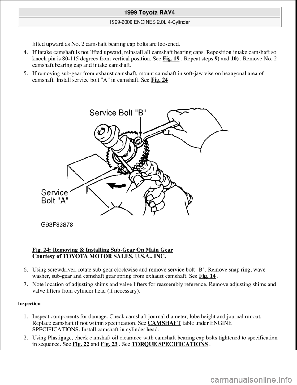
5. If removing sub-gear from exhaust camshaft, mount camshaft in soft-jaw vise on hexagonal area of
camshaft. Install service bolt "A" in camshaft. See Fig. 24
.
Fig. 24: Removing & Installing Sub
-Gear On Main Gear
Courtesy of TOYOTA MOTOR SALES, U.S.A., INC.
6. Using screwdriver, rotate sub-gear clockwise and remove service bolt "B". Remove snap ring, wave
washer, sub-gear and camshaft gear spring from exhaust camshaft. See Fig. 14
.
7. Note location of adjusting shims and valve lifters for reassembly reference. Remove adjusting shims and
valve lifters from cylinder head (if necessary).
Inspection
1. Inspect components for damage. Check camshaft journal diameter, lobe height and journal runout.
Replace camshaft if not within specification. See CAMSHAFT
table under ENGINE
SPECIFICATIONS. Install camshaft in cylinder head.
2. Using Plastigage, check camshaft oil clearance with camshaft bearing cap bolts tightened to specification
in sequence. See Fig. 22
and Fig. 23 . See TORQUE SPECIFICATIONS.
1999 Toyota RAV4
1999-2000 ENGINES 2.0L 4-Cylinder
Microsoft
Sunday, November 22, 2009 10:22:26 AMPage 35 © 2005 Mitchell Repair Information Company, LLC.
Page 719 of 1632
3. Check camshaft end play with camshaft bearing cap bolts tightened to specification. Replace camshaft
and/or cylinder head if camshaft end play is not within specification. See CAMSHAFT
table under
ENGINE SPECIFICATIONS.
4. Install both camshafts in cylinder head without sub-gear installed on exhaust camshaft. Install and tighten
camshaft bearing cap bolts to specification in sequence. See Fig. 22
and Fig. 23 . See TORQUE
SPECIFICATIONS .
5. Using dial indicator, check gear backlash between gears on camshafts. Replace camshafts if gear backlash
exceeds specification. See CAMSHAFT
table under ENGINE SPECIFICATIONS.
6. Measure length of camshaft gear spring. Replace camshaft gear spring if distance is not within
specification. See CAMSHAFT
table under ENGINE SPECIFICATIONS. Measure valve lifter diameter
and bore diameter. Ensure oil clearance is within specification. Replace components if not within
specification. See VALVE LIFTERS
table under ENGINE SPECIFICATIONS.
Installation
1. If installing sub-gear on exhaust camshaft, install camshaft gear spring, sub-gear, wave washer and snap
ring on exhaust camshaft. Ensure pins on main gear and sub-gear engage with ends of camshaft gear
spring.
2. Install service bolt "A" on sub-gear. See Fig. 24
. Using screwdriver, rotate sub-gear clockwise and align
hole in sub-gear with hole on main gear. Install service bolt "B". Remove service bolt "A".
3. Install adjusting shims and valve lifters in original location on cylinder head (if removed). Ensure valve
lifters rotate smoothly in cylinder head.
4. Coat thrust surfaces of camshafts with multipurpose grease. To install intake camshaft, rotate intake
camshaft so knock pin is at 80-115 degrees from vertical position, and install into cylinder head. See Fig.
19 .
5. Coat seal lip of NEW oil seal for intake camshaft with grease. Install oil seal onto front of intake camshaft
until oil seal is fully seated in cylinder head. Apply sealant to front camshaft bearing cap for intake
camshaft. See Fig. 25
.
1999 Toyota RAV4
1999-2000 ENGINES 2.0L 4-Cylinder
Microsoft
Sunday, November 22, 2009 10:22:26 AMPage 36 © 2005 Mitchell Repair Information Company, LLC.
Page 721 of 1632
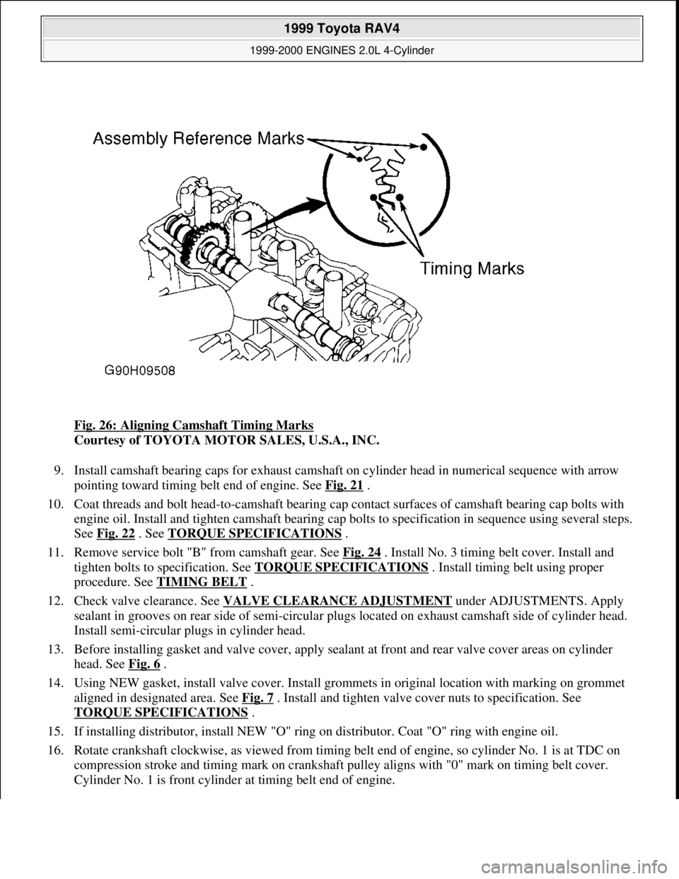
Fig. 26: Aligning Camshaft Timing Marks
Courtesy of TOYOTA MOTOR SALES, U.S.A., INC.
9. Install camshaft bearing caps for exhaust camshaft on cylinder head in numerical sequence with arrow
pointing toward timing belt end of engine. See Fig. 21
.
10. Coat threads and bolt head-to-camshaft bearing cap contact surfaces of camshaft bearing cap bolts with
engine oil. Install and tighten camshaft bearing cap bolts to specification in sequence using several steps.
See Fig. 22
. See TORQUE SPECIFICATIONS .
11. Remove service bolt "B" from camshaft gear. See Fig. 24
. Install No. 3 timing belt cover. Install and
tighten bolts to specification. See TORQUE SPECIFICATIONS
. Install timing belt using proper
procedure. See TIMING BELT
.
12. Check valve clearance. See VALVE CLEARANCE ADJUSTMENT
under ADJUSTMENTS. Apply
sealant in grooves on rear side of semi-circular plugs located on exhaust camshaft side of cylinder head.
Install semi-circular plugs in cylinder head.
13. Before installing gasket and valve cover, apply sealant at front and rear valve cover areas on cylinder
head. See Fig. 6
.
14. Using NEW gasket, install valve cover. Install grommets in original location with marking on grommet
aligned in designated area. See Fig. 7
. Install and tighten valve cover nuts to specification. See
TORQUE SPECIFICATIONS
.
15. If installing distributor, install NEW "O" ring on distributor. Coat "O" ring with engine oil.
16. Rotate crankshaft clockwise, as viewed from timing belt end of engine, so cylinder No. 1 is at TDC on
compression stroke and timing mark on crankshaft pulley aligns with "0" mark on timing belt cover.
C
ylinder No. 1 is front cylinder at timing belt end of engine.
1999 Toyota RAV4
1999-2000 ENGINES 2.0L 4-Cylinder
Microsoft
Sunday, November 22, 2009 10:22:26 AMPage 38 © 2005 Mitchell Repair Information Company, LLC.
Page 726 of 1632
4. Ensure valve lifter bore diameter in cylinder head is within specification. See VALVE LIFTERS table
under ENGINE SPECIFICATIONS.
Valve Springs
Ensure valve spring free length, pressure and out-of-square are within specification. See VALVES & VALVE
SPRINGS table under ENGINE SPECIFICATIONS.
Valve Stem Oil Seals
Intake valve stem oil seal is Brown. Exhaust valve stem oil seal is Black. Ensure proper valve stem oil seal is
installed. Lubricate valve stem oil seal with engine oil. Install valve stem oil seal using Oil Seal Installer (SST
09201-41020).
Valve Guides
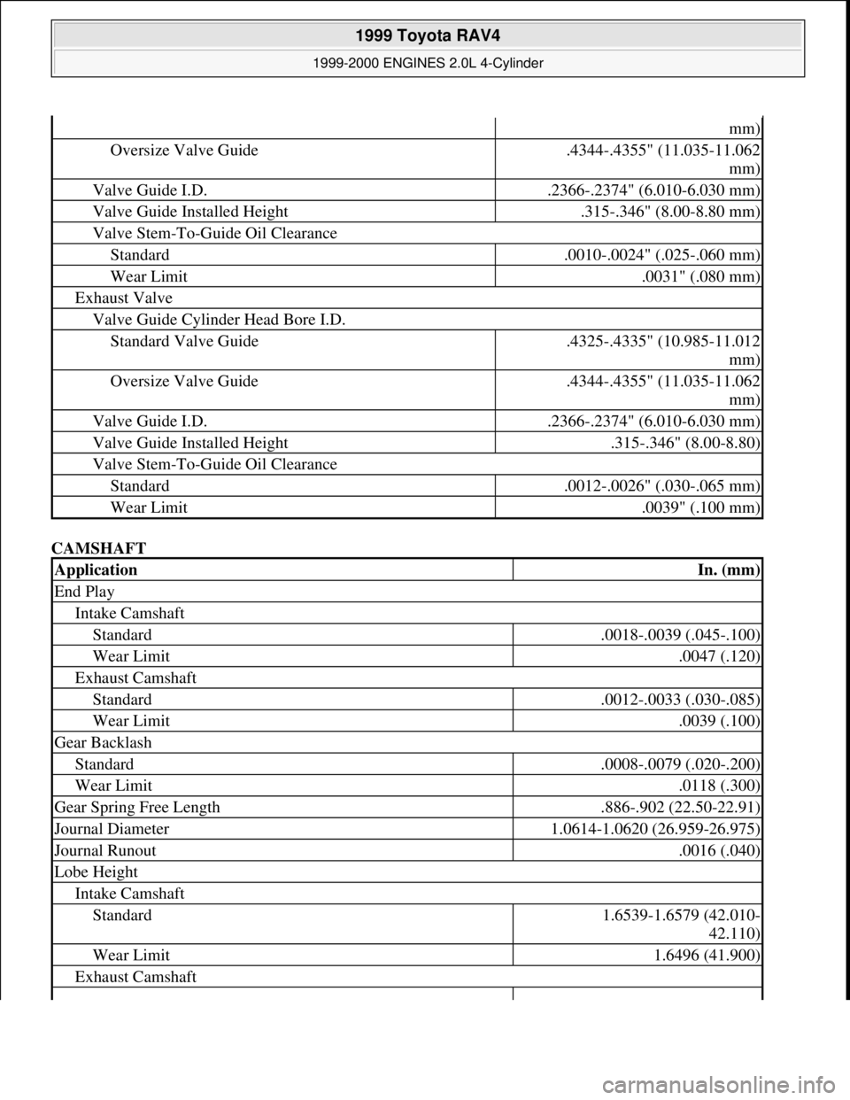
1. Ensure valve guide inside diameter is within specification. See CYLINDER HEAD table under ENGINE
SPECIFICATIONS. Replace valve guide if inside diameter exceeds specification.
2. To replace valve guide, heat cylinder head to 176-212°F (80-100°C). Using a hammer and Valve Guide
Remover/Installer (SST 09201-01060), drive valve guide from camshaft side of cylinder head.
3. Measure cylinder head valve guide bore inside diameter. If bore inside diameter is .4325-.4335" (10.985-
11.012 mm), use standard valve guide. If bore inside diameter is .4344-.4355" (11.035-11.062 mm), use
oversize valve guide.
4. If bore inside diameter exceeds .4335" (11.012 mm), machine valve guide bore to .4344-.4355" (11.035-
11.062 mm) for oversize valve guide. If bore inside diameter exceeds .4355" (11.062 mm), replace
cylinder head.
5. Intake valve guide is 1.516" (38.50 mm) long. Exhaust valve guide is 1.594" (40.50 mm) long. Ensure
proper valve guide is installed.
6. To install valve guide, heat cylinder head to 176-212°F (80-100°C). Using hammer and valve guide
remover/installer, drive valve guide in from camshaft side of cylinder head until valve guide installed
height is .315-.346" (8.00-8.80 mm). Valve guide installed height is measured from top of valve guide to
cylinder head surface. See Fig. 29
.
7. On all valve guide applications, use .236" (6.00 mm) reamer to ream valve guide to obtain correct valve
stem-to-guide oil clearance. See CYLINDER HEAD
table under ENGINE SPECIFICATIONS. CAUTION: Valve stems oil seals are painted a different color on top of oil seal for
specified valve application. Intake valve stem oil seal is Brown and
exhaust valve stem oil seal is Black. Ensure valve stem oil seal is installed
in proper location.
1999 Toyota RAV4
1999-2000 ENGINES 2.0L 4-Cylinder
Microsoft
Sunday, November 22, 2009 10:22:27 AMPage 43 © 2005 Mitchell Repair Information Company, LLC.
Page 727 of 1632
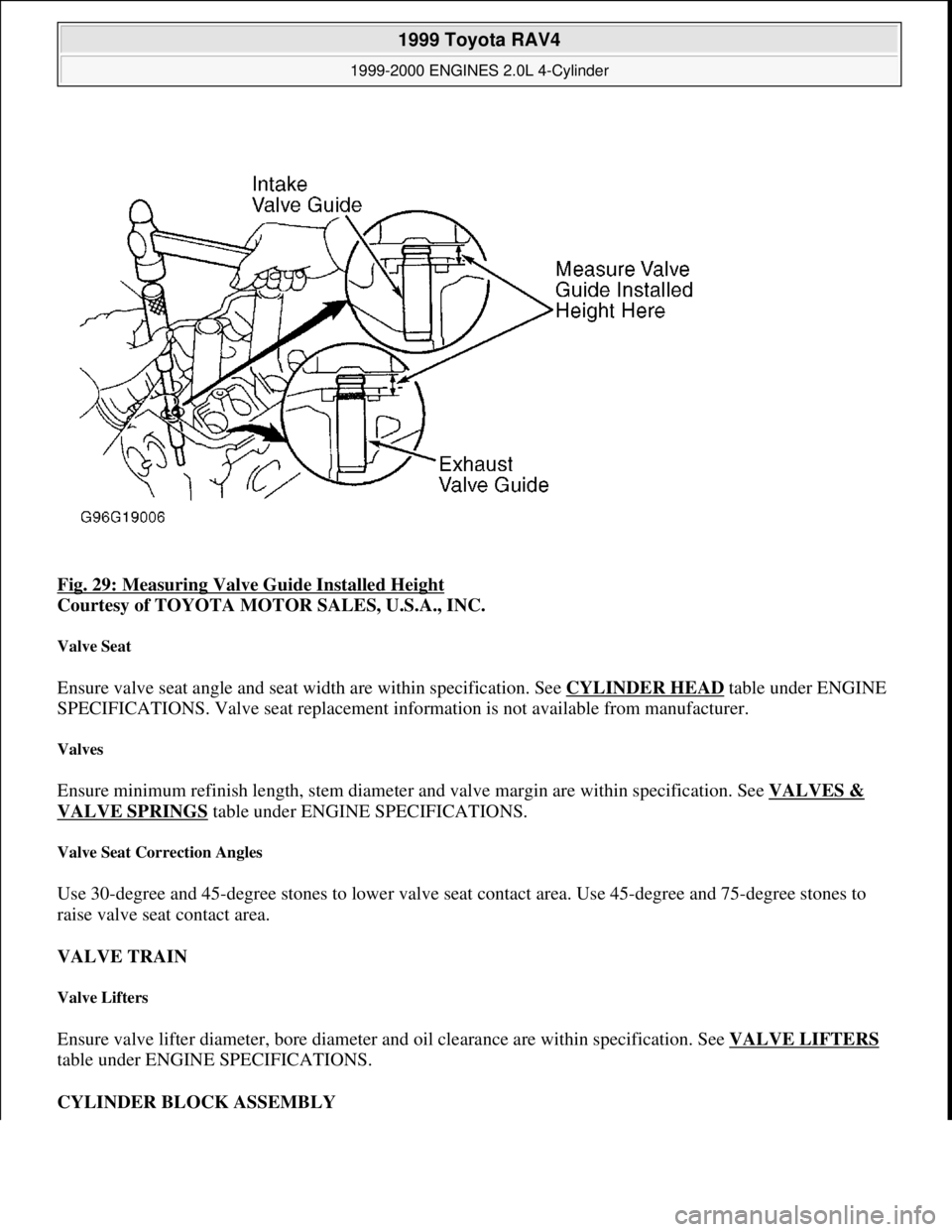
Fig. 29: Measuring Valve Guide Installed Height
Courtesy of TOYOTA MOTOR SALES, U.S.A., INC.
Valve Seat
Ensure valve seat angle and seat width are within specification. See CYLINDER HEAD table under ENGINE
SPECIFICATIONS. Valve seat replacement information is not available from manufacturer.
Valves
Ensure minimum refinish length, stem diameter and valve margin are within specification. See VALVES &
VALVE SPRINGS table under ENGINE SPECIFICATIONS.
Valve Seat Correction Angles
Use 30-degree and 45-degree stones to lower valve seat contact area. Use 45-degree and 75-degree stones to
raise valve seat contact area.
VALVE TRAIN
Valve Lifters
Ensure valve lifter diameter, bore diameter and oil clearance are within specification. See VALVE LIFTERS
table under ENGINE SPECIFICATIONS.
CYLINDER BLOCK ASSEMBLY
1999 Toyota RAV4
1999-2000 ENGINES 2.0L 4-Cylinder
Microsoft
Sunday, November 22, 2009 10:22:27 AMPage 44 © 2005 Mitchell Repair Information Company, LLC.
Page 738 of 1632
under REMOVAL & INSTALLATION. Remove oil pan. See OIL PANunder REMOVAL &
INSTALLATION.
2. Remove oil pump pick-up tube, gasket and oil baffle plate. Disconnect electrical connector for crankshaft
position sensor located on from of oil pump housing. Remove bolt and crankshaft position sensor from
front of oil pump housing.
3. Remove oil pump-to-cylinder block bolts. Using soft-face hammer, tap oil pump housing from cylinder
block. To disassemble oil pump, remove oil pump body cover bolts, oil pump body cover and "O" ring.
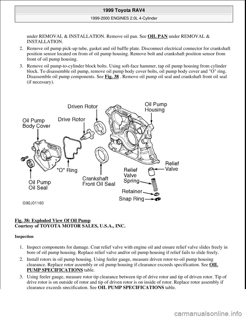
Disassemble oil pump components. See Fig. 38
. Remove oil pump oil seal and crankshaft front oil seal
(if necessary).
Fig. 38: Exploded View Of Oil Pump
Courtesy of TOYOTA MOTOR SALES, U.S.A., INC.
Inspection
1. Inspect components for damage. Coat relief valve with engine oil and ensure relief valve slides freely in
bore of oil pump housing. Replace relief valve and/or oil pump housing if relief fails to slide freely.
2. Install rotors in oil pump housing. Using feeler gauge, measure driven rotor-to-oil pump housing
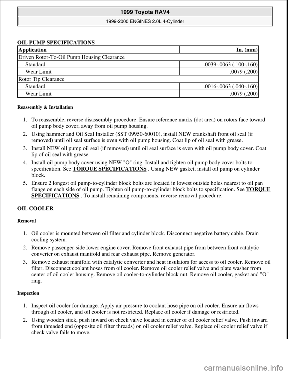
clearance. Replace rotor assembly or oil pump housing if clearance exceeds specification. See OIL
PUMP SPECIFICATIONS table.
3. Using feeler gauge, measure rotor tip clearance between tip of drive rotor and tip of driven rotor. Tip of
drive rotor is on outside of rotor and tip of driven rotor is on inside of rotor. Replace rotor assembly if
clearance exceeds specification. See OIL PUMP SPECIFICATIONS
table.
1999 Toyota RAV4
1999-2000 ENGINES 2.0L 4-Cylinder
Microsoft
Sunday, November 22, 2009 10:22:27 AMPage 55 © 2005 Mitchell Repair Information Company, LLC.
Page 739 of 1632
OIL PUMP SPECIFICATIONS
Reassembly & Installation
1. To reassemble, reverse disassembly procedure. Ensure reference marks (dot area) on rotors face toward
oil pump body cover, away from oil pump housing.
2. Using hammer and Oil Seal Installer (SST 09950-60010), install NEW crankshaft front oil seal (if
removed) until oil seal surface is even with oil pump housing. Coat lip of oil seal with grease.
3. Install NEW oil pump oil seal (if removed) until oil seal surface is even with oil pump body cover. Coat
lip of oil seal with grease.
4. Install oil pump body cover using NEW "O" ring. Install and tighten oil pump body cover bolts to
specification. See TORQUE SPECIFICATIONS
. Using NEW gasket, install oil pump on cylinder
block.
5. Ensure 2 longest oil pump-to-cylinder block bolts are located in lowest outside holes nearest to oil pan
flange on each side of oil pump. Tighten oil pump-to-cylinder block bolts to specification. See TORQUE
SPECIFICATIONS . To install remaining components, reverse removal procedure.
OIL COOLER
Removal
1. Oil cooler is mounted between oil filter and cylinder block. Disconnect negative battery cable. Drain
cooling system.
2. Remove passenger-side lower engine cover. Remove front exhaust pipe from between front catalytic
converter on exhaust manifold and rear exhaust pipe. Remove generator.
3. Remove exhaust manifold with catalytic converter and heat insulators for access to oil cooler. Remove oil
filter. Disconnect coolant hoses from oil cooler. Remove oil cooler relief valve and plate washer from
center of oil cooler housing. Remove oil cooler-to-cylinder block nut. Remove oil cooler, gasket and "O"
ring.
Inspection
1. Inspect oil cooler for damage. Apply air pressure to coolant hose pipe on oil cooler. Ensure air flows
through oil cooler, and oil cooler is not restricted. Replace oil cooler if damage or restricted.
2. Using wooden stick, push inward on check valve located in center of oil cooler relief valve. Push inward
from threaded end (opposite oil filter threads) on oil cooler relief valve. Replace oil cooler relief valve if
check valve fails to move.
ApplicationIn. (mm)
Driven Rotor-To-Oil Pump Housing Clearance
Standard.0039-.0063 (.100-.160)
Wear Limit.0079 (.200)
Rotor Tip Clearance
Standard.0016-.0063 (.040-.160)
Wear Limit.0079 (.200)
1999 Toyota RAV4
1999-2000 ENGINES 2.0L 4-Cylinder
Microsoft
Sunday, November 22, 2009 10:22:27 AMPage 56 © 2005 Mitchell Repair Information Company, LLC.
Page 747 of 1632
CAMSHAFT
mm)
Oversize Valve Guide.4344-.4355" (11.035-11.062
mm)
Valve Guide I.D..2366-.2374" (6.010-6.030 mm)
Valve Guide Installed Height.315-.346" (8.00-8.80 mm)
Valve Stem-To-Guide Oil Clearance
Standard.0010-.0024" (.025-.060 mm)
Wear Limit.0031" (.080 mm)
Exhaust Valve
Valve Guide Cylinder Head Bore I.D.
Standard Valve Guide.4325-.4335" (10.985-11.012
mm)
Oversize Valve Guide.4344-.4355" (11.035-11.062
mm)
Valve Guide I.D..2366-.2374" (6.010-6.030 mm)
Valve Guide Installed Height.315-.346" (8.00-8.80)
Valve Stem-To-Guide Oil Clearance
Standard.0012-.0026" (.030-.065 mm)
Wear Limit.0039" (.100 mm)
ApplicationIn. (mm)
End Play
Intake Camshaft
Standard.0018-.0039 (.045-.100)
Wear Limit.0047 (.120)
Exhaust Camshaft
Standard.0012-.0033 (.030-.085)
Wear Limit.0039 (.100)
Gear Backlash
Standard.0008-.0079 (.020-.200)
Wear Limit.0118 (.300)
Gear Spring Free Length.886-.902 (22.50-22.91)
Journal Diameter1.0614-1.0620 (26.959-26.975)
Journal Runout.0016 (.040)
Lobe Height
Intake Camshaft
Standard1.6539-1.6579 (42.010-
42.110)
Wear Limit1.6496 (41.900)
Exhaust Camshaft
1999 Toyota RAV4
1999-2000 ENGINES 2.0L 4-Cylinder
Microsoft
Sunday, November 22, 2009 10:22:27 AMPage 64 © 2005 Mitchell Repair Information Company, LLC.
Page 748 of 1632
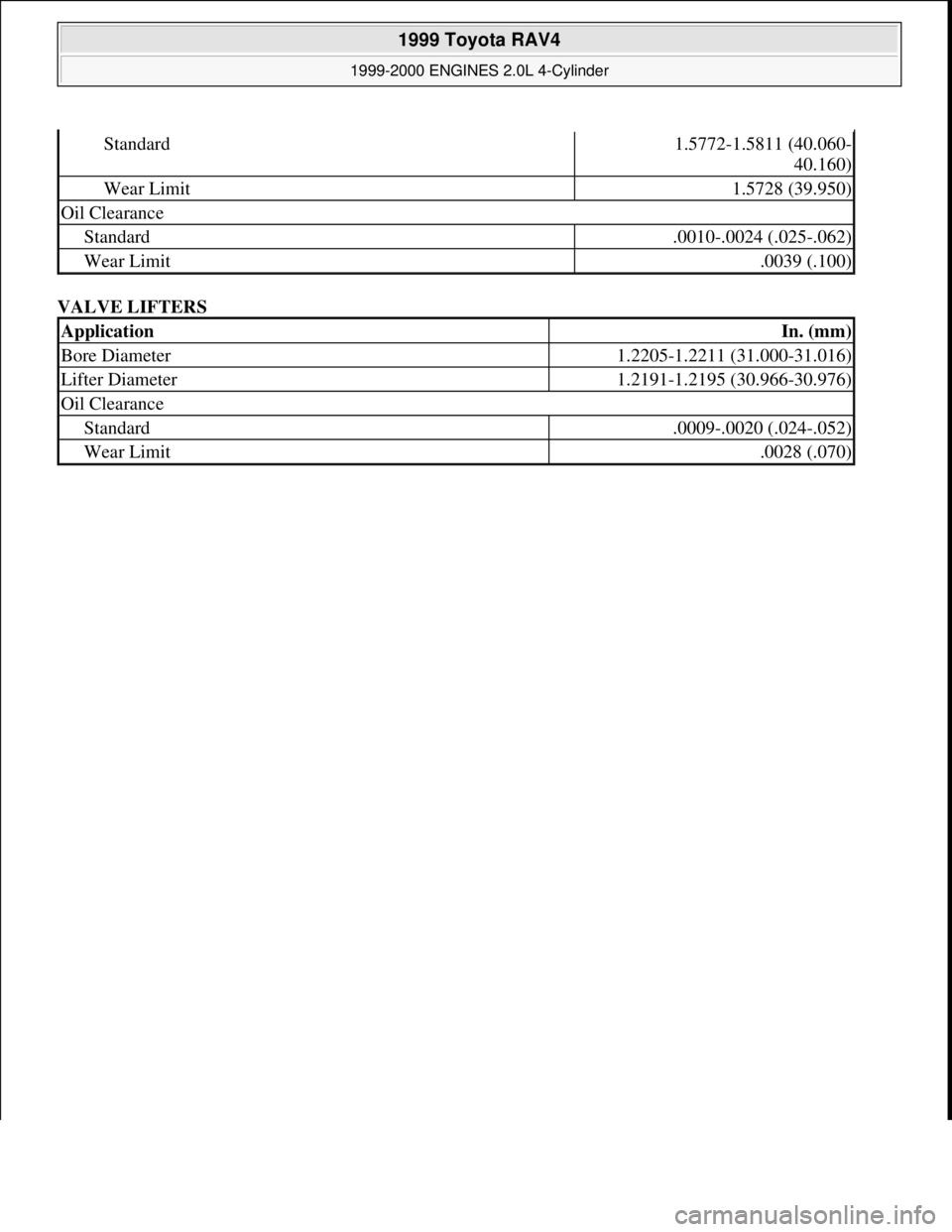
VALVE LIFTERS
Standard1.5772-1.5811 (40.060-
40.160)
Wear Limit1.5728 (39.950)
Oil Clearance
Standard.0010-.0024 (.025-.062)
Wear Limit.0039 (.100)
ApplicationIn. (mm)
Bore Diameter1.2205-1.2211 (31.000-31.016)
Lifter Diameter1.2191-1.2195 (30.966-30.976)
Oil Clearance
Standard.0009-.0020 (.024-.052)
Wear Limit.0028 (.070)
1999 Toyota RAV4
1999-2000 ENGINES 2.0L 4-Cylinder
Microsoft
Sunday, November 22, 2009 10:22:27 AMPage 65 © 2005 Mitchell Repair Information Company, LLC.
Page 750 of 1632
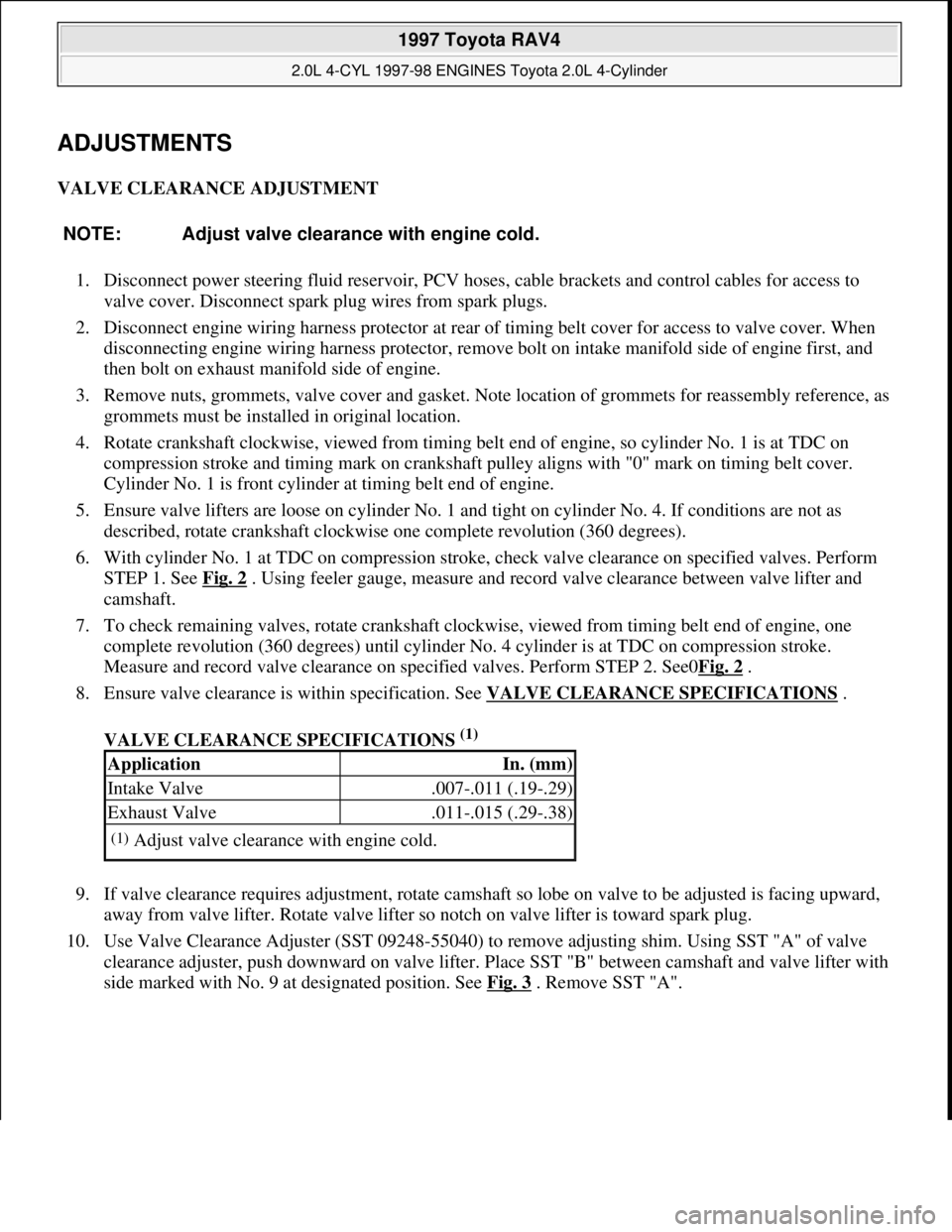
ADJUSTMENTS
VALVE CLEARANCE ADJUSTMENT
1. Disconnect power steering fluid reservoir, PCV hoses, cable brackets and control cables for access to
valve cover. Disconnect spark plug wires from spark plugs.
2. Disconnect engine wiring harness protector at rear of timing belt cover for access to valve cover. When
disconnecting engine wiring harness protector, remove bolt on intake manifold side of engine first, and
then bolt on exhaust manifold side of engine.
3. Remove nuts, grommets, valve cover and gasket. Note location of grommets for reassembly reference, as
grommets must be installed in original location.
4. Rotate crankshaft clockwise, viewed from timing belt end of engine, so cylinder No. 1 is at TDC on
compression stroke and timing mark on crankshaft pulley aligns with "0" mark on timing belt cover.
Cylinder No. 1 is front cylinder at timing belt end of engine.
5. Ensure valve lifters are loose on cylinder No. 1 and tight on cylinder No. 4. If conditions are not as
described, rotate crankshaft clockwise one complete revolution (360 degrees).
6. With cylinder No. 1 at TDC on compression stroke, check valve clearance on specified valves. Perform
STEP 1. See Fig. 2
. Using feeler gauge, measure and record valve clearance between valve lifter and
camshaft.
7. To check remaining valves, rotate crankshaft clockwise, viewed from timing belt end of engine, one
complete revolution (360 degrees) until cylinder No. 4 cylinder is at TDC on compression stroke.
Measure and record valve clearance on specified valves. Perform STEP 2. See0Fig. 2
.
8. Ensure valve clearance is within specification. See VALVE CLEARANCE SPECIFICATIONS
.
VALVE CLEARANCE SPECIFICATIONS
(1)
9. If valve clearance requires adjustment, rotate camshaft so lobe on valve to be adjusted is facing upward,
away from valve lifter. Rotate valve lifter so notch on valve lifter is toward spark plug.
10. Use Valve Clearance Adjuster (SST 09248-55040) to remove adjusting shim. Using SST "A" of valve
clearance adjuster, push downward on valve lifter. Place SST "B" between camshaft and valve lifter with
side marked with No. 9 at desi
gnated position. See Fig. 3. Remove SST "A". NOTE: Adjust valve clearance with engine cold.
ApplicationIn. (mm)
Intake Valve.007-.011 (.19-.29)
Exhaust Valve.011-.015 (.29-.38)
(1)Adjust valve clearance with engine cold.
1997 Toyota RAV4
2.0L 4-CYL 1997-98 ENGINES Toyota 2.0L 4-Cylinder
Microsoft
Sunday, November 22, 2009 10:23:30 AMPage 2 © 2005 Mitchell Repair Information Company, LLC.