catalytic converter TOYOTA RAV4 1996 Service Repair Manual
[x] Cancel search | Manufacturer: TOYOTA, Model Year: 1996, Model line: RAV4, Model: TOYOTA RAV4 1996Pages: 1632, PDF Size: 41.64 MB
Page 127 of 1632
transmission shift lever assembly for removal of transmission shift lever assembly.
5. Remove bolts and transmission shift lever assembly from top of transmission. Remove bolts, transfer case
shift lever assembly and cushions. Cushions are located between transfer case shift lever assembly and
the transfer case.
6. Raise and support vehicle. Disconnect necessary electrical connectors and hoses for transmission and
transfer case removal. Place reference marks on drive shaft flanges for reassembly reference. Remove
bolts and all drive shafts.
7. Remove transmission oil dipstick, dipstick tube and "O" ring. Loosen oil cooler lines at side of
transmission. Remove stabilizer bar-to-frame mounting bracket bolts at each end of stabilizer bar.
Remove lower engine cover.
8. Remove plug on front of transmission for access to torque converter bolts. Remove torque converter
bolts. Remove support brackets and front exhaust pipe with front catalytic converter and gasket. Front
exhaust pipe fits between exhaust manifolds and rear catalytic converter and exhaust pipe.
9. Remove starter. Support transmission with transmission jack. Remove transmission crossmember located
below the transmission. Lower rear of transmission. Separate wiring harness from transmission and
transfer case.
10. Remove oil cooler line mounting bolts from torque converter housing. Disconnect oil cooler lines from
side of transmission. Remove transmission-to-cylinder block bolts. Lower transmission with transfer case
from vehicle.
Installation
1. Before installing transmission, use dial indicator to check drive plate runout. Drive plate runout should be
checked right next to the starter ring gear on the drive plate. Replace drive plate if runout
exceeds .0079" (.200 mm).
2. Install torque converter on transmission. To ensure torque converter is fully seated, torque converter
depth should be checked. Using straightedge and caliper, measure torque converter depth from torque
converter bolt lug on torque converter to the surface on transmission. See Fig. 1
.
3. Torque converter depth should be more than .618" (15.70 mm). If torque converter depth is less than
specified, check for improperly seated torque converter.
4. To install, reverse removal procedure. Tighten all bolts/nuts to specification. See TORQUE
SPECIFICATIONS . When installing torque converter bolts, apply Loctite to torque converter bolt
threads before installing. Ensure the Gray torque converter bolt is installed first before installing the
remaining torque converter bolts.
5. Use NEW gaskets and NEW nuts when installing front exhaust pipe. Adjust all cables, shift linkages and
fill with ATF. See appropriate TRANSMISSION SERVICING article.
Removal (Land Cruiser 1998)
1. Disconnect negative battery cable. Remove battery and battery tray. Remove serpentine belt, fan and fan CAUTION: When lowering rear of transmission, use care not to damage cooling
fan, brake booster and brake line.
1998 Toyota Avalon XLS
TRANSMISSION SERVICING - A/T 1997-98 TRANSMISSION SERVICING Toyota - Transmission Removal &
Installation
Helpmelearn
November-03-08 10:30:28 AMPage 15 © 2005 Mitchell Repair Information Company, LLC.
Page 141 of 1632
2. With engine and transmission removed, remove starter if not previously removed. Remove torque
converter cover from front of transmission. Remove torque converter bolts. Remove transmission-to-
cylinder block bolts. Separate transmission from engine.
Installation
1. Before installing transaxle, use dial indicator to check drive plate runout. Drive plate runout should be
checked right next to the starter ring gear on the drive plate. Replace drive plate if runout
exceeds .0079" (.200 mm).
2. Install torque converter on transmission. To ensure torque converter is fully seated, torque converter
depth should be checked. Using straightedge and caliper, measure torque converter depth from torque
converter bolt lug on torque converter to the surface on transmission. See Fig. 1
.
3. Torque converter depth should be more than 1.250" (31.75 mm) for 2.7L 4-cylinder or .707" (17.95 mm)
for 3.4L V6. If torque converter depth is less than specified, check for improperly seated torque converter.
4. To install, reverse removal procedure. Tighten all bolts/nuts to specification. See TORQUE
SPECIFICATIONS . When installing torque converter bolts, apply Loctite to torque converter bolt
threads before installing.
5. Once engine and transmission are installed, adjust all cables and fill with ATF. See appropriate
TRANSMISSION SERVICING article.
Removal (T100 4WD)
1. Disconnect negative battery cable. Remove knob from transfer case shift lever. Remove screws and boot
from transfer case shift lever. Remove snap ring and transfer case shift lever from transfer case.
2. Disconnect throttle valve cable from throttle body. Raise and support vehicle. Remove lower engine
cover. Remove transmission oil dipstick, dipstick tube and "O" ring.
3. Place reference marks on drive shaft flanges for reassembly reference. Remove drive shafts. Remove
front exhaust pipe located between exhaust manifold and catalytic converter.
4. Disconnect speedometer cable and necessary electrical connectors for transmission and transfer case
removal. Disconnect shift linkage at side of transmission. Remove shift linkage cross shaft located
between frame and shift lever on transmission.
5. Remove starter. Remove transmission oil cooler pipes and brackets as necessary. Remove stiffener plates
located on each side of cylinder block. Stiffener plate fits between side of cylinder block and front of
transmission.
6. Remove stabilizer bar. Support transmission with floor jack. Remove bolts and dynamic damper
transmission crossmember. Dynamic damper is located on driver's side of transmission crossmember,
next to transmission mount bolts and is fastened to bottom of transmission crossmember using 2 bolts.
7. Remove transmission mount-to-transmission crossmember bolts. Remove transmission crossmember
located below transmission and transfer case.
8. Remove torque converter cover from front of transmission. Remove torque converter bolts. Remove
transmission-to-cylinder block bolts. Lower transmission with transfer case from vehicle.
Installation
1998 Toyota Avalon XLS
TRANSMISSION SERVICING - A/T 1997-98 TRANSMISSION SERVICING Toyota - Transmission Removal &
Installation
Helpmelearn
November-03-08 10:30:29 AMPage 29 © 2005 Mitchell Repair Information Company, LLC.
Page 142 of 1632
1. Before installing transmission, use dial indicator to check drive plate runout. Drive plate runout should be
checked right next to the starter ring gear on the drive plate. Replace drive plate if runout
exceeds .0079" (.200 mm).
2. Install torque converter on transmission. To ensure torque converter is fully seated, torque converter
depth should be checked. Using straightedge and caliper, measure torque converter depth from torque
converter bolt lug on torque converter to the surface on transmission. See Fig. 1
.
3. Torque converter depth should be more than .707" (17.95 mm). If torque converter depth is less than
specified, check for improperly seated torque converter.
4. To install, reverse removal procedure. Tighten all bolts/nuts to specification. See TORQUE
SPECIFICATIONS . When installing torque converter bolts, apply Loctite to torque converter bolt
threads before installing.
5. Apply grease to transfer case shift lever before installing. Use NEW gasket when installing front exhaust
pipe. Adjust all cables, shift linkages and fill with ATF. See appropriate TRANSMISSION SERVICING
article.
Removal (4Runner 2WD)
1. Disconnect negative battery cable. Remove transmission oil dipstick, dipstick tube and "O" ring.
Disconnect throttle valve cable from throttle body.
2. Raise and support vehicle. Remove lower engine cover. Disconnect shift linkage for transmission at
gearshift. Remove front exhaust pipe, located between exhaust manifold and catalytic converter on rear
exhaust pipe.
3. Place reference marks on drive shaft flange for reassembly reference. Remove drive shaft. Disconnect
necessary electrical connectors for transmission removal. Remove transmission oil cooler pipes and
brackets as necessary.
4. Support transmission with floor jack. Remove transmission crossmember, located below transmission.
Remove starter.
5. Remove cover from front of transmission for access to torque converter bolts. On 3.4L, note location of
Green torque converter bolt for reassembly reference. Remove torque converter bolts. Remove
transmission-to-cylinder block bolts. Lower transmission from vehicle.
Installation
1. Before installing transmission, use dial indicator to check drive plate runout. Drive plate runout should be
checked right next to the starter ring gear on the drive plate. Replace drive plate if runout
exceeds .0079" (.200 mm).
2. Install torque converter on transmission. To ensure torque converter is fully seated, torque converter
depth should be checked. Using straightedge and caliper, measure torque converter depth from torque
converter bolt lug on torque converter to the surface on transmission. See Fig. 1
.
3. Torque converter depth should be more than 1.250" (31.75 mm) for 2.7L 4-cylinder or .707" (17.95 mm)
for 3.4L V6. If torque converter depth is less than specified, check for improperly seated torque converter.
4. To install, reverse removal procedure. Tighten all bolts/nuts to specification. See TORQUE
SPECIFICATIONS . When installing torque converter bolts, apply Loctite to torque converter bolt
threads before installin
g. On 3.4L V6, ensure the Green torque converter bolt is installed first before
1998 Toyota Avalon XLS
TRANSMISSION SERVICING - A/T 1997-98 TRANSMISSION SERVICING Toyota - Transmission Removal &
Installation
Helpmelearn
November-03-08 10:30:29 AMPage 30 © 2005 Mitchell Repair Information Company, LLC.
Page 143 of 1632
installing the remaining torque converter bolts.
5. Use NEW gasket when installing front exhaust pipe. Adjust all cables, shift linkages and fill with ATF.
See appropriate TRANSMISSION SERVICING article.
Removal (4Runner 4WD)
1. Disconnect negative battery cable. Remove rear console upper panel and disconnect electrical connectors.
Rear console upper panel is located on the top of the console, near emergency brake lever.
2. Remove heater control knobs from instrument panel. Using screwdriver, pry heater control plate from
center finish panel on instrument panel. Center finish panel is the panel that fits around the radio and air
outlet ducts, located at center of instrument panel.
3. Remove screws and disconnect electrical connectors from center finish panel from instrument panel.
Remove center finish panel.
4. On models without 2-4 selector button on side of transfer case shift lever, unscrew knob from transfer
case shift lever. On models with2-4 selector button on side of transfer case shift lever, remove screw from
knob on transfer case shift lever. Remove knob from transfer case shift lever and lay aside with wire
attached.
5. On all models, remove upper console panel which contains boot for transfer case shift lever and is located
on center console. On models with 2-4 selector button on side of transfer case shift lever, disconnect
electrical connector for 2-4 selector button and remove knob on transfer case shift lever.
6. On all models, remove screws, clips and front console box, located around transmission shift lever
assembly and transfer case shift lever. Raise and support vehicle. Disconnect shift linkage at transmission
shift lever.
7. Disconnect electrical connectors for removal of transmission shift lever assembly. Remove transmission
shift lever assembly. Remove snap ring and transfer case shift lever.
8. Remove transmission oil dipstick, dipstick tube and "O" ring. Remove lower engine covers. Place
reference marks on drive shaft flanges for reassembly reference. Remove drive shafts.
9. Remove front exhaust pipe, located between exhaust manifold and catalytic converter on rear exhaust
pipe. Disconnect and necessary electrical connectors for transmission and transfer case removal. Separate
wiring harness from transmission and transfer case.
10. Remove starter. Remove transmission oil cooler pipes and brackets as necessary. On 3.4L V6, it may be
necessary to remove stabilizer bar.
11. On all models, support transmission with floor jack. Remove rear transmission mount-to-transmission
crossmember bolts. Remove transmission crossmember, located below transmission and transfer case.
12. Remove torque converter cover from front of transmission. On 3.4L, note location of Green torque
converter bolt for re-installation reference. Remove torque converter bolts. Remove transmission-to-
cylinder block bolts. Lower transmission with transfer case from vehicle.
Installation
1. Before installing transmission, use dial indicator to check drive plate runout. Drive plate runout should be
checked right next to the starter ring gear on the drive plate. Replace drive plate if runout
exceeds .0079" (.200 mm).
2. Install torque converter on transmission. To ensure torque converter is fully seated, torque converter
1998 Toyota Avalon XLS
TRANSMISSION SERVICING - A/T 1997-98 TRANSMISSION SERVICING Toyota - Transmission Removal &
Installation
Helpmelearn
November-03-08 10:30:29 AMPage 31 © 2005 Mitchell Repair Information Company, LLC.
Page 148 of 1632
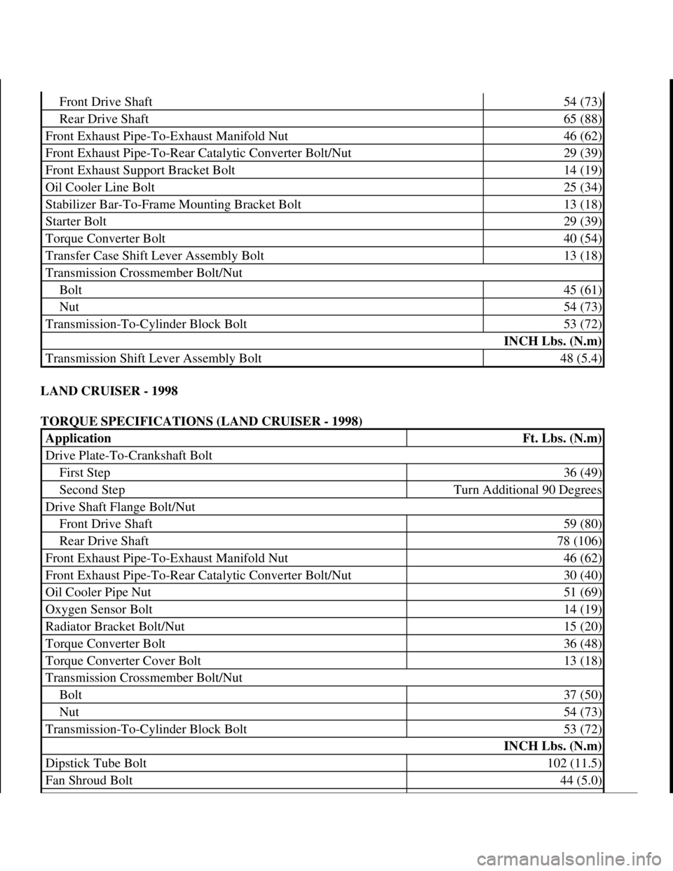
LAND CRUISER - 1998
TORQUE SPECIFICATIONS (LAND CRUISER - 1998)
Front Drive Shaft54 (73)
Rear Drive Shaft65 (88)
Front Exhaust Pipe-To-Exhaust Manifold Nut46 (62)
Front Exhaust Pipe-To-Rear Catalytic Converter Bolt/Nut29 (39)
Front Exhaust Support Bracket Bolt14 (19)
Oil Cooler Line Bolt25 (34)
Stabilizer Bar-To-Frame Mounting Bracket Bolt13 (18)
Starter Bolt29 (39)
Torque Converter Bolt40 (54)
Transfer Case Shift Lever Assembly Bolt13 (18)
Transmission Crossmember Bolt/Nut
Bolt45 (61)
Nut54 (73)
Transmission-To-Cylinder Block Bolt53 (72)
INCH Lbs. (N.m)
Transmission Shift Lever Assembly Bolt48 (5.4)
ApplicationFt. Lbs. (N.m)
Drive Plate-To-Crankshaft Bolt
First Step36 (49)
Second StepTurn Additional 90 Degrees
Drive Shaft Flange Bolt/Nut
Front Drive Shaft59 (80)
Rear Drive Shaft78 (106)
Front Exhaust Pipe-To-Exhaust Manifold Nut46 (62)
Front Exhaust Pipe-To-Rear Catalytic Converter Bolt/Nut30 (40)
Oil Cooler Pipe Nut51 (69)
Oxygen Sensor Bolt14 (19)
Radiator Bracket Bolt/Nut15 (20)
Torque Converter Bolt36 (48)
Torque Converter Cover Bolt13 (18)
Transmission Crossmember Bolt/Nut
Bolt37 (50)
Nut54 (73)
Transmission-To-Cylinder Block Bolt53 (72)
INCH Lbs. (N.m)
Dipstick Tube Bolt102 (11.5)
Fan Shroud Bolt44 (5.0)
1998 Toyota Avalon XLS
TRANSMISSION SERVICING - A/T 1997-98 TRANSMISSION SERVICING Toyota - Transmission Removal &
Installation
Helpmelearn
November-03-08 10:30:29 AMPage 36 © 2005 Mitchell Repair Information Company, LLC.
Page 700 of 1632
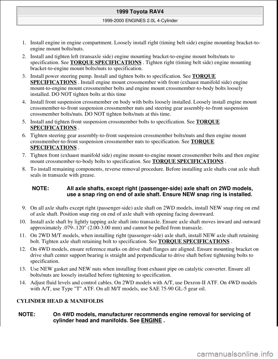
1. Install engine in engine compartment. Loosely install right (timing belt side) engine mounting bracket-to-
engine mount bolts/nuts.
2. Install and tighten left (transaxle side) engine mounting bracket-to-engine mount bolts/nuts to
specification. See TORQUE SPECIFICATIONS
. Tighten right (timing belt side) engine mounting
bracket-to-engine mount bolts/nuts to specification.
3. Install power steering pump. Install and tighten bolts to specification. See TORQUE
SPECIFICATIONS . Install engine mount crossmember with front (exhaust manifold side) engine
mount-to-engine mount crossmember bolts and engine mount crossmember-to-body bolts loosely
installed. DO NOT tighten bolts at this time
4. Install front suspension crossmember on body with bolts loosely installed. Loosely install engine mount
crossmember-to-front suspension crossmember nuts and steering gear assembly-to-front suspension
crossmember bolts/nuts. DO NOT tighten bolts/nuts at this time.
5. Install and tighten front suspension crossmember bolts to specification. See TORQUE
SPECIFICATIONS .
6. Tighten steering gear assembly-to-front suspension crossmember bolts/nuts and then engine mount
crossmember-to-front suspension crossmember nuts to specification. See TORQUE
SPECIFICATIONS .
7. Tighten front (exhaust manifold side) engine mount-to-engine mount crossmember bolts and then engine
mount crossmember-to-body bolts to specification. See TORQUE SPECIFICATIONS
.
8. To install remaining components, reverse removal procedure. Before installing axle shafts coat axle shaft
seals in transaxle with grease.
9. On all axle shafts except right (passenger-side) axle shaft on 2WD models, install NEW snap ring on end
of axle shaft. Position snap ring on end of axle shaft with opening facing downward.
10. Install axle shaft by lightly tapping axle shaft into transaxle. Ensure axle shaft moves inward and outward
approximately .079-.120" (2.00-3.00 mm) and cannot be pulled from transaxle.
11. On 2WD M/T models, when installing right (passenger-side) axle shaft, install NEW axle shaft retaining
bolt. Tighten axle shaft retaining bolt to specification. See TORQUE SPECIFICATIONS
.
12. On 4WD models, ensure reference marks on drive shaft flanges are aligned. Ensure mounting bracket on
drive shaft center support bearing is straight and perpendicular to drive shaft before tightening bolts to
specification.
13. Use NEW gasket and NEW nuts when installing front exhaust pipe on catalytic converter. Ensure all
bolts/nuts are loosely installed before tightening to specification.
14. Adjust fluid levels and control cables. On 2WD models with A/T, use Dexron-II ATF. On 4WD models
with A/T, use Type "T" ATF. On all M/T models, use SAE 75-90 GL-5 gear oil.
CYLINDER HEAD & MANIFOLDS NOTE: All axle shafts, except right (passenger-side) axle shaft on 2WD models,
use a snap ring on end of axle shaft. Ensure NEW snap ring is installed.
NOTE: On 4WD models, manufacturer recommends engine removal for servicing of
cylinder head and manifolds. See ENGINE
.
1999 Toyota RAV4
1999-2000 ENGINES 2.0L 4-Cylinder
Microsoft
Sunday, November 22, 2009 10:22:26 AMPage 17 © 2005 Mitchell Repair Information Company, LLC.
Page 701 of 1632
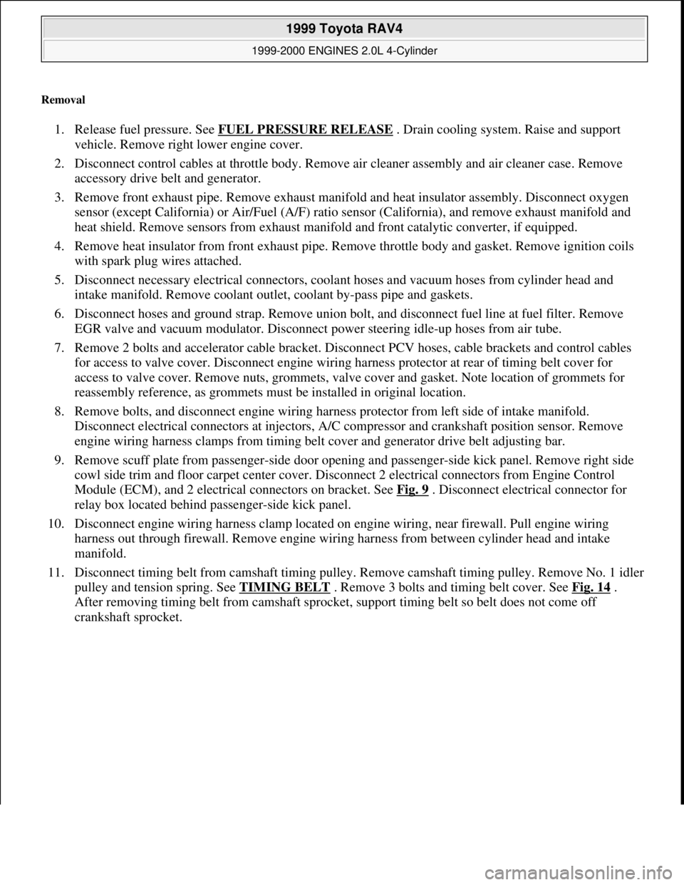
Removal
1. Release fuel pressure. See FUEL PRESSURE RELEASE . Drain cooling system. Raise and support
vehicle. Remove right lower engine cover.
2. Disconnect control cables at throttle body. Remove air cleaner assembly and air cleaner case. Remove
accessory drive belt and generator.
3. Remove front exhaust pipe. Remove exhaust manifold and heat insulator assembly. Disconnect oxygen
sensor (except California) or Air/Fuel (A/F) ratio sensor (California), and remove exhaust manifold and
heat shield. Remove sensors from exhaust manifold and front catalytic converter, if equipped.
4. Remove heat insulator from front exhaust pipe. Remove throttle body and gasket. Remove ignition coils
with spark plug wires attached.
5. Disconnect necessary electrical connectors, coolant hoses and vacuum hoses from cylinder head and
intake manifold. Remove coolant outlet, coolant by-pass pipe and gaskets.
6. Disconnect hoses and ground strap. Remove union bolt, and disconnect fuel line at fuel filter. Remove
EGR valve and vacuum modulator. Disconnect power steering idle-up hoses from air tube.
7. Remove 2 bolts and accelerator cable bracket. Disconnect PCV hoses, cable brackets and control cables
for access to valve cover. Disconnect engine wiring harness protector at rear of timing belt cover for
access to valve cover. Remove nuts, grommets, valve cover and gasket. Note location of grommets for
reassembly reference, as grommets must be installed in original location.
8. Remove bolts, and disconnect engine wiring harness protector from left side of intake manifold.
Disconnect electrical connectors at injectors, A/C compressor and crankshaft position sensor. Remove
engine wiring harness clamps from timing belt cover and generator drive belt adjusting bar.
9. Remove scuff plate from passenger-side door opening and passenger-side kick panel. Remove right side
cowl side trim and floor carpet center cover. Disconnect 2 electrical connectors from Engine Control
Module (ECM), and 2 electrical connectors on bracket. See Fig. 9
. Disconnect electrical connector for
relay box located behind passenger-side kick panel.
10. Disconnect engine wiring harness clamp located on engine wiring, near firewall. Pull engine wiring
harness out through firewall. Remove engine wiring harness from between cylinder head and intake
manifold.
11. Disconnect timing belt from camshaft timing pulley. Remove camshaft timing pulley. Remove No. 1 idler
pulley and tension spring. See TIMING BELT
. Remove 3 bolts and timing belt cover. See Fig. 14 .
After removing timing belt from camshaft sprocket, support timing belt so belt does not come off
crankshaft sprocket.
1999 Toyota RAV4
1999-2000 ENGINES 2.0L 4-Cylinder
Microsoft
Sunday, November 22, 2009 10:22:26 AMPage 18 © 2005 Mitchell Repair Information Company, LLC.
Page 725 of 1632
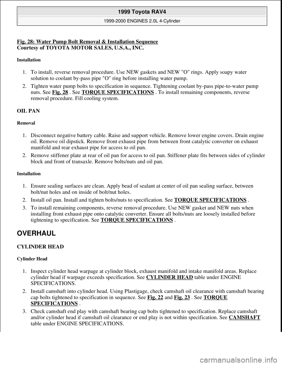
Fig. 28: Water Pump Bolt Removal & Installation Sequence
Courtesy of TOYOTA MOTOR SALES, U.S.A., INC.
Installation
1. To install, reverse removal procedure. Use NEW gaskets and NEW "O" rings. Apply soapy water
solution to coolant by-pass pipe "O" ring before installing water pump.
2. Tighten water pump bolts to specification in sequence. Tightening coolant by-pass pipe-to-water pump
nuts. See Fig. 28
. See TORQUE SPECIFICATIONS . To install remaining components, reverse
removal procedure. Fill cooling system.
OIL PAN
Removal
1. Disconnect negative battery cable. Raise and support vehicle. Remove lower engine covers. Drain engine
oil. Remove oil dipstick. Remove front exhaust pipe from between front catalytic converter on exhaust
manifold and rear exhaust pipe for access to oil pan.
2. Remove stiffener plate at rear of oil pan for access to oil pan. Stiffener plate fits between sides of cylinder
block and front of transaxle. Remove bolts/nuts and oil pan.
Installation
1. Ensure sealing surfaces are clean. Apply bead of sealant at center of oil pan sealing surface, between
bolt/nut holes and on inside of bolt/nut holes.
2. Install oil pan. Install and tighten bolts/nuts to specification. See TORQUE SPECIFICATIONS
.
3. To install remaining components, reverse removal procedure. Use NEW gasket and NEW nuts when
installing front exhaust pipe onto catalytic converter. Ensure all bolts/nuts are loosely installed before
tightening to specification. See TORQUE SPECIFICATIONS
.
OVERHAUL
CYLINDER HEAD
Cylinder Head
1. Inspect cylinder head warpage at cylinder block, exhaust manifold and intake manifold areas. Replace
cylinder head if warpage exceeds specification. See CYLINDER HEAD
table under ENGINE
SPECIFICATIONS.
2. Install camshaft into cylinder head. Using Plastigage, check camshaft oil clearance with camshaft bearing
cap bolts tightened to specification in sequence. See Fig. 22
and Fig. 23 . See TORQUE
SPECIFICATIONS .
3. Check camshaft end play with camshaft bearing cap bolts tightened to specification. Replace camshaft
and/or cylinder head if camshaft oil clearance or end play is not within specification. See CAMSHAFT
table under ENGINE SPECIFICATIONS.
1999 Toyota RAV4
1999-2000 ENGINES 2.0L 4-Cylinder
Microsoft
Sunday, November 22, 2009 10:22:27 AMPage 42 © 2005 Mitchell Repair Information Company, LLC.
Page 739 of 1632
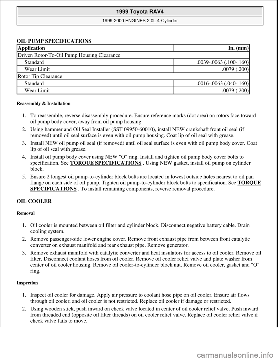
OIL PUMP SPECIFICATIONS
Reassembly & Installation
1. To reassemble, reverse disassembly procedure. Ensure reference marks (dot area) on rotors face toward
oil pump body cover, away from oil pump housing.
2. Using hammer and Oil Seal Installer (SST 09950-60010), install NEW crankshaft front oil seal (if
removed) until oil seal surface is even with oil pump housing. Coat lip of oil seal with grease.
3. Install NEW oil pump oil seal (if removed) until oil seal surface is even with oil pump body cover. Coat
lip of oil seal with grease.
4. Install oil pump body cover using NEW "O" ring. Install and tighten oil pump body cover bolts to
specification. See TORQUE SPECIFICATIONS
. Using NEW gasket, install oil pump on cylinder
block.
5. Ensure 2 longest oil pump-to-cylinder block bolts are located in lowest outside holes nearest to oil pan
flange on each side of oil pump. Tighten oil pump-to-cylinder block bolts to specification. See TORQUE
SPECIFICATIONS . To install remaining components, reverse removal procedure.
OIL COOLER
Removal
1. Oil cooler is mounted between oil filter and cylinder block. Disconnect negative battery cable. Drain
cooling system.
2. Remove passenger-side lower engine cover. Remove front exhaust pipe from between front catalytic
converter on exhaust manifold and rear exhaust pipe. Remove generator.
3. Remove exhaust manifold with catalytic converter and heat insulators for access to oil cooler. Remove oil
filter. Disconnect coolant hoses from oil cooler. Remove oil cooler relief valve and plate washer from
center of oil cooler housing. Remove oil cooler-to-cylinder block nut. Remove oil cooler, gasket and "O"
ring.
Inspection
1. Inspect oil cooler for damage. Apply air pressure to coolant hose pipe on oil cooler. Ensure air flows
through oil cooler, and oil cooler is not restricted. Replace oil cooler if damage or restricted.
2. Using wooden stick, push inward on check valve located in center of oil cooler relief valve. Push inward
from threaded end (opposite oil filter threads) on oil cooler relief valve. Replace oil cooler relief valve if
check valve fails to move.
ApplicationIn. (mm)
Driven Rotor-To-Oil Pump Housing Clearance
Standard.0039-.0063 (.100-.160)
Wear Limit.0079 (.200)
Rotor Tip Clearance
Standard.0016-.0063 (.040-.160)
Wear Limit.0079 (.200)
1999 Toyota RAV4
1999-2000 ENGINES 2.0L 4-Cylinder
Microsoft
Sunday, November 22, 2009 10:22:27 AMPage 56 © 2005 Mitchell Repair Information Company, LLC.
Page 740 of 1632
Installation
1. To install, reverse removal procedure. Use a NEW "O" ring and gasket. Coat "O" ring with engine oil.
Coat threads and area below head of oil cooler relief valve with engine oil.
2. Install oil cooler with oil cooler-to-cylinder block nut and oil cooler relief valve loosely installed. Tighten
oil cooler relief valve, and then nut, to specification. See TORQUE SPECIFICATIONS
.
3. Use NEW gasket and NEW nuts when installing front exhaust pipe to catalytic converter. Ensure all
bolts/nuts are loosely installed before tightening to specification. See TORQUE SPECIFICATIONS
.
Add engine oil as needed. Fill cooling system.
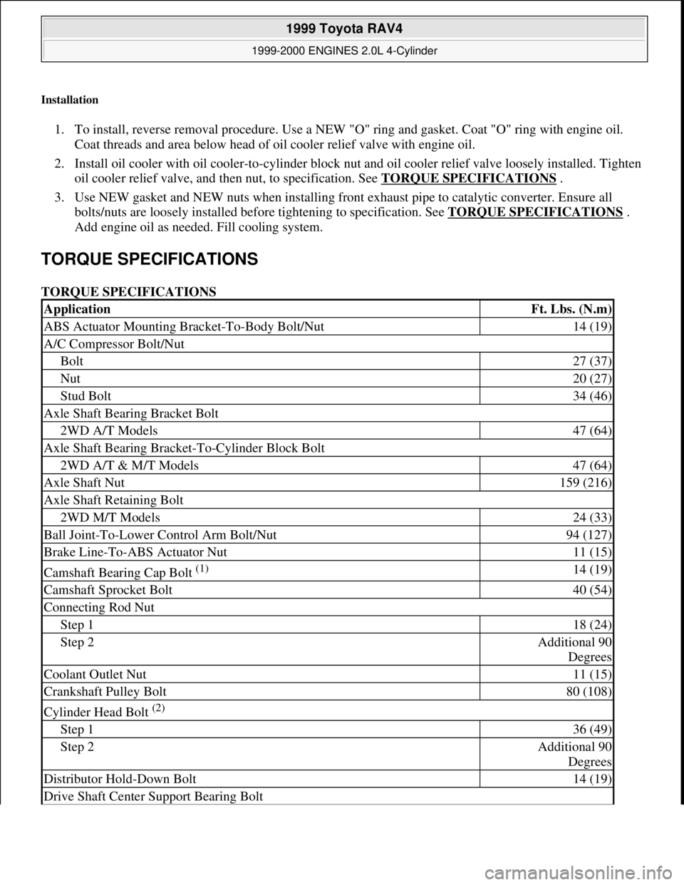
TORQUE SPECIFICATIONS
TORQUE SPECIFICATIONS
ApplicationFt. Lbs. (N.m)
ABS Actuator Mounting Bracket-To-Body Bolt/Nut14 (19)
A/C Compressor Bolt/Nut
Bolt27 (37)
Nut20 (27)
Stud Bolt34 (46)
Axle Shaft Bearing Bracket Bolt
2WD A/T Models47 (64)
Axle Shaft Bearing Bracket-To-Cylinder Block Bolt
2WD A/T & M/T Models47 (64)
Axle Shaft Nut159 (216)
Axle Shaft Retaining Bolt
2WD M/T Models24 (33)
Ball Joint-To-Lower Control Arm Bolt/Nut94 (127)
Brake Line-To-ABS Actuator Nut11 (15)
Camshaft Bearing Cap Bolt (1) 14 (19)
Camshaft Sprocket Bolt40 (54)
Connecting Rod Nut
Step 118 (24)
Step 2Additional 90
Degrees
Coolant Outlet Nut11 (15)
Crankshaft Pulley Bolt80 (108)
Cylinder Head Bolt (2)
Step 136 (49)
Step 2Additional 90
Degrees
Distributor Hold-Down Bolt14 (19)
Drive Shaft Center Support Bearing Bolt
1999 Toyota RAV4
1999-2000 ENGINES 2.0L 4-Cylinder
Microsoft
Sunday, November 22, 2009 10:22:27 AMPage 57 © 2005 Mitchell Repair Information Company, LLC.