battery TOYOTA RAV4 1996 Service Repair Manual
[x] Cancel search | Manufacturer: TOYOTA, Model Year: 1996, Model line: RAV4, Model: TOYOTA RAV4 1996Pages: 1632, PDF Size: 41.64 MB
Page 3 of 1632
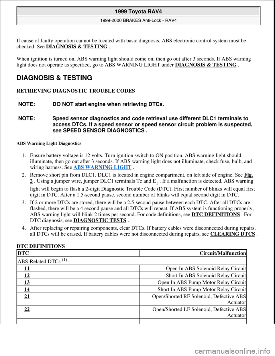
If cause of faulty operation cannot be located with basic diagnosis, ABS electronic control system must be
checked. See DIAGNOSIS & TESTING
.
When ignition is turned on, ABS warning light should come on, then go out after 3 seconds. If ABS warning
light does not operate as specified, go to ABS WARNING LIGHT under DIAGNOSIS & TESTING
.
DIAGNOSIS & TESTING
RETRIEVING DIAGNOSTIC TROUBLE CODES
ABS Warning Light Diagnostics
1. Ensure battery voltage is 12 volts. Turn ignition switch to ON position. ABS warning light should
illuminate, then go out after 3 seconds. If ABS warning light does not illuminate, check fuse, bulb, and
wiring harness. See ABS WARNING LIGHT
.
2. Remove short pin from DLC1. DLC1 is located in engine compartment, on left side of engine. See Fig.
2 . Using a jumper wire, jumper DLC1 terminals Tc and E1 . If a malfunction is detected, ABS warning
light will begin to flash a 2-digit Diagnostic Trouble Code (DTC). First number of blinks will equal first
digit in DTC. After a 1.5-second pause, second number of blinks will equal second digit in DTC.
3. If 2 or more DTCs are stored, there will be a 2.5-second pause between each DTC. After all DTCs are
flashed, there will be a 4 second pause and all DTCs will repeat. If ABS system is functioning properly,
ABS warning light will blink 2 times per second. For code definitions, see DTC DEFINITIONS
. For
DTC diagnosis, see DIAGNOSTIC TESTS
.
4. After replacing or repairing components, clear DTCs. If battery cables were disconnected during repairs,
all DTCs will be erased. If battery cables were not disconnected during repairs, see CLEARING DTCS
.
DTC DEFINITIONS NOTE: DO NOT start engine when retrieving DTCs.
NOTE: Speed sensor diagnostics and code retrieval use different DLC1 terminals to
access DTCs. If a speed sensor or speed sensor circuit problem is suspected,
see SPEED SENSOR DIAGNOSTICS
.
DTCCircuit/Malfunction
ABS-Related DTCs (1)
11 Open In ABS Solenoid Relay Circuit
12 Short In ABS Solenoid Relay Circuit
13 Open In ABS Pump Motor Relay Circuit
14 Short In ABS Pump Motor Relay Circuit
21 Open/Shorted RF Solenoid, Defective ABS
Actuator
22 Open/Shorted LF Solenoid, Defective ABS
Actuator
1999 Toyota RAV4
1999-2000 BRAKES Anti-Lock - RAV4
Microsoft
Sunday, November 22, 2009 10:06:17 AMPage 3 © 2005 Mitchell Repair Information Company, LLC.
Page 4 of 1632
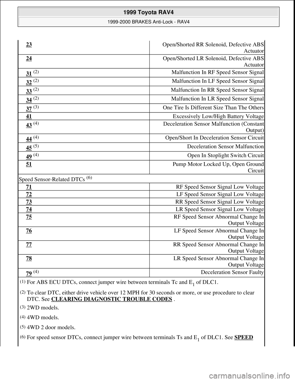
23 Open/Shorted RR Solenoid, Defective ABS
Actuator
24 Open/Shorted LR Solenoid, Defective ABS
Actuator
31 (2) Malfunction In RF Speed Sensor Signal
32 (2) Malfunction In LF Speed Sensor Signal
33 (2) Malfunction In RR Speed Sensor Signal
34 (2) Malfunction In LR Speed Sensor Signal
37 (3) One Tire Is Different Size Than The Others
41 Excessively Low/High Battery Voltage
43 (4) Deceleration Sensor Malfunction (Constant
Output)
44 (4) Open/Short In Deceleration Sensor Circuit
45 (5) Deceleration Sensor Malfunction
49 (4) Open In Stoplight Switch Circuit
51 Pump Motor Locked Up, Open Ground
Circuit
Speed Sensor-Related DTCs (6)
71 RF Speed Sensor Signal Low Voltage
72 LF Speed Sensor Signal Low Voltage
73 RR Speed Sensor Signal Low Voltage
74 LR Speed Sensor Signal Low Voltage
75 RF Speed Sensor Abnormal Change In
Output Voltage
76 LF Speed Sensor Abnormal Change In
Output Voltage
77 RR Speed Sensor Abnormal Change In
Output Voltage
78 LR Speed Sensor Abnormal Change In
Output Voltage
79 (4) Deceleration Sensor Faulty
(1)For ABS ECU DTCs, connect jumper wire between terminals Tc and E1 of DLC1.
(2)To clear DTC, either drive vehicle over 12 MPH for 30 seconds or more, or use procedure to clear
DTC. See CLEARING DIAGNOSTIC TROUBLE CODES
.
(3)2WD models.
(4)4WD models.
(5)4WD 2 door models.
(6)For speed sensor DTCs, connect jumper wire between terminals Ts and E1 of DLC1. See SPEED
1999 Toyota RAV4
1999-2000 BRAKES Anti-Lock - RAV4
Microsoft
Sunday, November 22, 2009 10:06:17 AMPage 4 © 2005 Mitchell Repair Information Company, LLC.
Page 5 of 1632
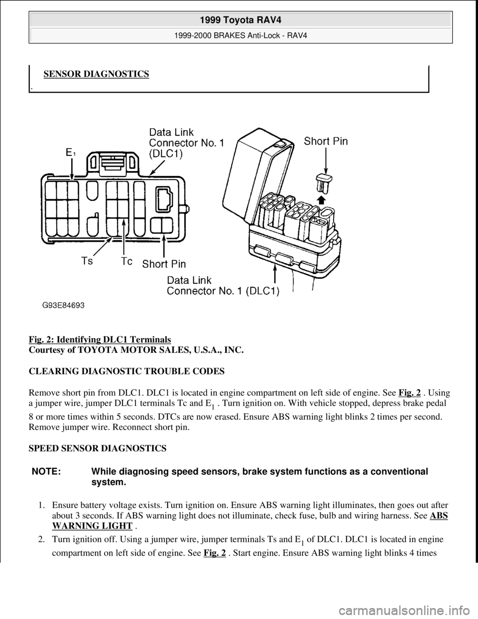
Fig. 2: Identifying DLC1 Terminals
Courtesy of TOYOTA MOTOR SALES, U.S.A., INC.
CLEARING DIAGNOSTIC TROUBLE CODES
Remove short pin from DLC1. DLC1 is located in engine compartment on left side of engine. See Fig. 2
. Using
a jumper wire, jumper DLC1 terminals Tc and E
1 . Turn ignition on. With vehicle stopped, depress brake pedal
8 or more times within 5 seconds. DTCs are now erased. Ensure ABS warning light blinks 2 times per second.
Remove jumper wire. Reconnect short pin.
SPEED SENSOR DIAGNOSTICS
1. Ensure battery voltage exists. Turn ignition on. Ensure ABS warning light illuminates, then goes out after
about 3 seconds. If ABS warning light does not illuminate, check fuse, bulb and wiring harness. See ABS
WARNING LIGHT .
2. Turn ignition off. Using a jumper wire, jumper terminals Ts and E
1 of DLC1. DLC1 is located in engine
compartment on left side of en
gine. See Fig. 2. Start engine. Ensure ABS warning light blinks 4 times
.SENSOR DIAGNOSTICS
NOTE: While diagnosing speed sensors, brake system functions as a conventional
system.
1999 Toyota RAV4
1999-2000 BRAKES Anti-Lock - RAV4
Microsoft
Sunday, November 22, 2009 10:06:17 AMPage 5 © 2005 Mitchell Repair Information Company, LLC.
Page 10 of 1632
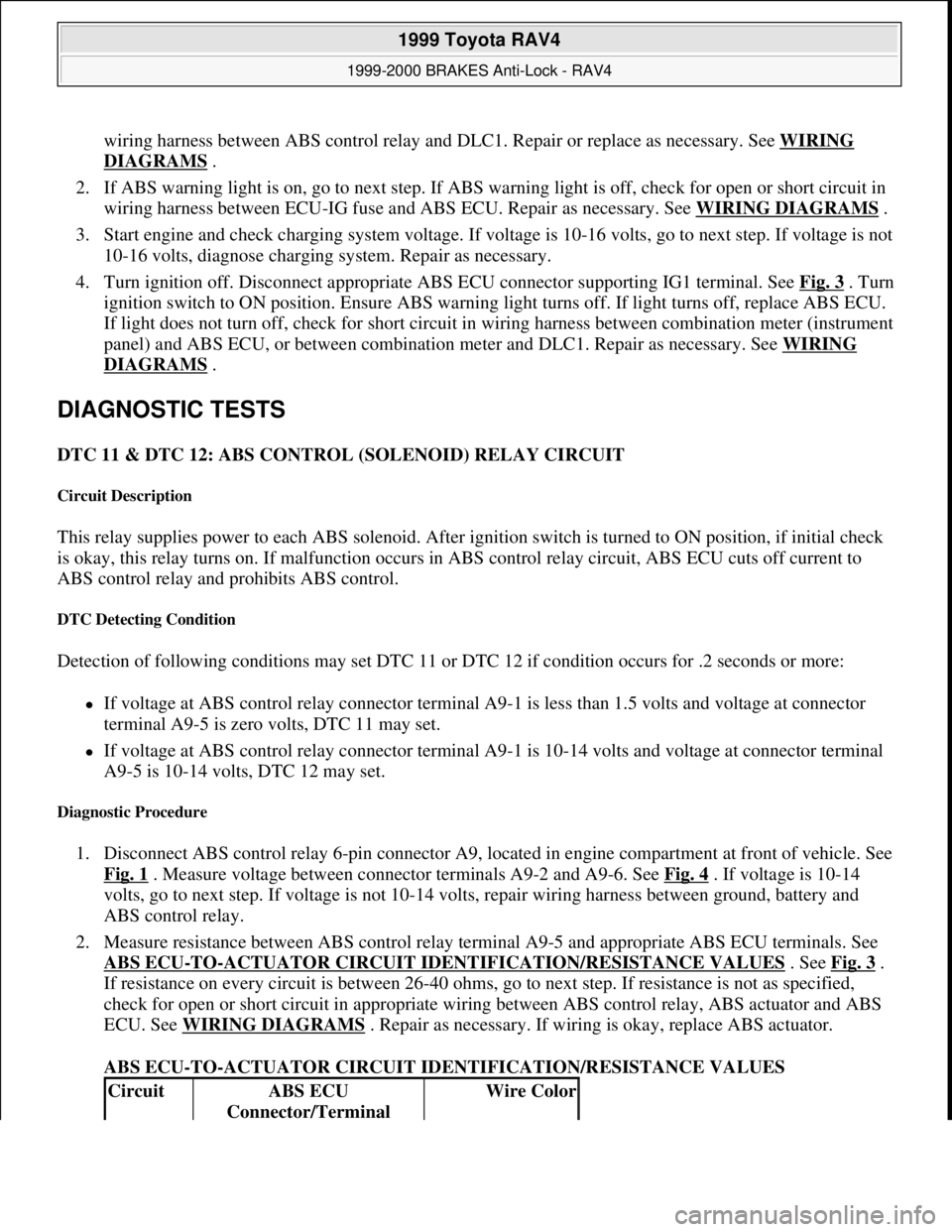
wiring harness between ABS control relay and DLC1. Repair or replace as necessary. See WIRING
DIAGRAMS .
2. If ABS warning light is on, go to next step. If ABS warning light is off, check for open or short circuit in
wiring harness between ECU-IG fuse and ABS ECU. Repair as necessary. See WIRING DIAGRAMS
.
3. Start engine and check charging system voltage. If voltage is 10-16 volts, go to next step. If voltage is not
10-16 volts, diagnose charging system. Repair as necessary.
4. Turn ignition off. Disconnect appropriate ABS ECU connector supporting IG1 terminal. See Fig. 3
. Turn
ignition switch to ON position. Ensure ABS warning light turns off. If light turns off, replace ABS ECU.
If light does not turn off, check for short circuit in wiring harness between combination meter (instrument
panel) and ABS ECU, or between combination meter and DLC1. Repair as necessary. See WIRING
DIAGRAMS .
DIAGNOSTIC TESTS
DTC 11 & DTC 12: ABS CONTROL (SOLENOID) RELAY CIRCUIT
Circuit Description
This relay supplies power to each ABS solenoid. After ignition switch is turned to ON position, if initial check
is okay, this relay turns on. If malfunction occurs in ABS control relay circuit, ABS ECU cuts off current to
ABS control relay and prohibits ABS control.
DTC Detecting Condition
Detection of following conditions may set DTC 11 or DTC 12 if condition occurs for .2 seconds or more:
If voltage at ABS control relay connector terminal A9-1 is less than 1.5 volts and voltage at connector
terminal A9-5 is zero volts, DTC 11 may set.
If voltage at ABS control relay connector terminal A9-1 is 10-14 volts and voltage at connector terminal
A9-5 is 10-14 volts, DTC 12 may set.
Diagnostic Procedure
1. Disconnect ABS control relay 6-pin connector A9, located in engine compartment at front of vehicle. See
Fig. 1
. Measure voltage between connector terminals A9-2 and A9-6. See Fig. 4 . If voltage is 10-14
volts, go to next step. If voltage is not 10-14 volts, repair wiring harness between ground, battery and
ABS control relay.
2. Measure resistance between ABS control relay terminal A9-5 and appropriate ABS ECU terminals. See
ABS ECU
-TO-ACTUATOR CIRCUIT IDENTIFICATION/RESISTANCE VALUES . See Fig. 3 .
If resistance on every circuit is between 26-40 ohms, go to next step. If resistance is not as specified,
check for open or short circuit in appropriate wiring between ABS control relay, ABS actuator and ABS
ECU. See WIRING DIAGRAMS
. Repair as necessary. If wiring is okay, replace ABS actuator.
ABS ECU-TO-ACTUATOR CIRCUIT IDENTIFICATION/RESISTANCE VALUES
CircuitABS ECU
Connector/TerminalWire Color
1999 Toyota RAV4
1999-2000 BRAKES Anti-Lock - RAV4
Microsoft
Sunday, November 22, 2009 10:06:17 AMPage 10 © 2005 Mitchell Repair Information Company, LLC.
Page 12 of 1632
DTC Detecting Condition
Detection of any of the following conditions may set DTC 13 or DTC 14 if condition occurs for .2 seconds or
more:
If voltage at ABS control relay connector terminal A8-4 is less than 1.5 volts, and voltage at connector
terminal A8-2 is zero volts, DTC 13 may set.
If voltage at ABS control relay connector terminal A8-4 is 10-14 volts, and voltage at connector terminal
A8-2 is 10-14 volts, DTC 14 may set.
Diagnostic Procedure
1. Disconnect ABS control relay connector A8, located in engine compartment at front of vehicle. See Fig.
1 . Measure voltage between ground and motor relay connector terminal A8-1. See Fig. 5 . If voltage is
10-14 volts, go to next step. If voltage is not 10-14 volts, repair wiring harness between battery and motor
relay. See WIRING DIAGRAMS
.
2. Disconnect 2 ABS actuator connectors. Check for continuity on Blue/Red wire between ABS actuator
connector terminal A7-2 and ABS control relay connector terminal A8-2. Also check for continuity on
Blue/Red wire between ABS actuator connector terminal A7-3 and ABS ECU connector terminal A16-
10. See Fig. 5
. Continuity should exist. If continuity is not present on either wire, repair open circuit on
affected wire between ABS control relay and ABS ECU. If continuity is present on both wires, go to next
step.
3. Check resistance between ABS actuator terminals A7-2 and A7-3. Resistance should be 26-40 ohms. If
resistance is as specified, go to next step. If resistance is not as specified, replace ABS actuator.
4. Check ABS control relay. See MOTOR RELAY SECTION
under ABS CONTROL RELAY under
COMPONENT TESTS. Replace relay as necessary. If relay tests okay, go to next step.
5. Check for open or short circuit in wiring harness between ABS control relay and ABS ECU. Repair as
necessary. See WIRING DIAGRAMS
. If circuit is okay, go to next step.
6. Clear DTCs and then recheck for DTCs. See RETRIEVING DTCS
under DIAGNOSIS & TESTING. If
same DTC is output after DTC is cleared, check contact condition of each connection. Repair as
necessar
y. If connections are okay, replace ABS ECU.
1999 Toyota RAV4
1999-2000 BRAKES Anti-Lock - RAV4
Microsoft
Sunday, November 22, 2009 10:06:17 AMPage 12 © 2005 Mitchell Repair Information Company, LLC.
Page 14 of 1632
DTC 21, DTC 22, DTC 23 & DTC 24: ABS ACTUATOR SOLENOID CIRCUIT
Circuit Description
This solenoid turns on when signals are received from ABS ECU and controls pressure acting on calipers/wheel
cylinders, thus controlling braking force. If malfunction occurs in actuator solenoid circuit, ABS ECU cuts off
current to ABS control relay and prohibits ABS control.
DTC Detecting Conditions
If the following conditions continue for .05 seconds or more, DTC will set. Voltage at ABS control relay
connector terminal A9-1 is less than 1.5 volts, and one of the following conditions is met:
If power transistor of ABS ECU is on, and voltage at terminal SFRR or terminal SFRH is zero volts or
battery voltage is detected, DTC 21 will set.
If power transistor of ABS ECU is on, and voltage at terminal SFLR or terminal SFLH is zero volts or
battery voltage is detected, DTC 22 will set.
If power transistor of ABS ECU is on, and voltage at terminal SRRR or terminal SRRH is zero volts or
battery voltage is detected, DTC 23 will set.
If power transistor of ABS ECU is on, and voltage at terminal SRLR or terminal SRLH is zero volts or
battery voltage is detected, DTC 24 will set.
Diagnostic Procedure
1. Disconnect 2 ABS actuator connectors. Check continuity between actuator connector terminal A7- 4 and
actuator connector terminals A6-1 through A6-8. See Fig. 6
. Continuity should exist at each pair of
terminals. Check resistance at each pair of terminals. Resistance should be 4.3 ohms for each solenoid
coil at terminals SFRR, SFLR, SRRR and SRLR. Resistance should be 8.8 ohms for each solenoid coil at
terminals SFRH, SFLH, SRRH and SRLH. See WIRING DIAGRAMS
. If continuity and resistance is
as specified, go to next step. If continuity and resistance is not as specified, replace ABS actuator.
2. Check for open or short circuit in wiring harness between ABS ECU and actuator. Repair as necessary.
See WIRING DIAGRAMS
. If circuits are okay, go to next step.
3. Clear DTCs and then recheck for DTCs. See RETRIEVING DTCS
under DIAGNOSIS & TESTING. If
same DTC is output after DTC is cleared, check contact condition of each connection. Repair as
necessar
y. If connections are okay, replace ABS ECU.
1999 Toyota RAV4
1999-2000 BRAKES Anti-Lock - RAV4
Microsoft
Sunday, November 22, 2009 10:06:17 AMPage 14 © 2005 Mitchell Repair Information Company, LLC.
Page 16 of 1632
1. Disconnect front speed sensor connector. Measure resistance between speed sensor connector terminals.
Resistance should be 1.4-1.8 k/ohms. Measure resistance between ground and each speed sensor
connector terminal. Resistance should be one megohm or more. If resistance is as specified, go to step 3 .
If resistance is not as specified, replace speed sensor.
2. Disconnect rear speed sensor connector. Measure resistance between speed sensor connector terminals.
Resistance should be 1.28-1.48 k/ohms. Measure resistance between ground and each speed sensor
connector terminal. Resistance should be one megohm or more. If resistance is as specified, go to next
step. If resistance is not as specified, replace speed sensor.
3. Check for open or short circuit in wiring harness between affected speed sensor and ABS ECU. See
WIRING DIAGRAMS
. Repair as necessary. If wiring harness is okay, go to next step.
4. Check speed sensor installation. Ensure mounting bolt is tightened to specification. See TORQUE
SPECIFICATIONS . Ensure zero clearance exists between sensor and front steering knuckle or rear axle
carrier. Replace speed sensor if necessary. If speed sensor installation is okay, check speed sensor signal.
See SPEED SENSOR DIAGNOSTICS
under DIAGNOSIS & TESTING. If signal is normal, go to next
step.
5. If oscilloscope is available, check speed sensor signal wave form. Remove ABS ECU. Do not disconnect
electrical connectors. Connect oscilloscope between GND terminal and terminals FR+, FL+, RR+ and
RL+ at ABS ECU connector. See Fig. 3
. Drive vehicle at 19 MPH and observe signal wave form. Signal
should be smooth and consistent without any irregular wave forms. If wave form is smooth and
consistent, replace ABS ECU. If wave form is not smooth and consistent, go to next step.
6. Check speed sensor rotor for missing teeth or damage. Check sensor tip for scratches, damage or foreign
objects. Replace components as necessary. If rotor and sensor are okay, replace ABS ECU.
DTC 37: TIRES OF DIFFERENT SIZE (2WD MODELS ONLY)
DTC Detecting Condition
Detection of the following condition may set DTC 37:
Driving vehicle at speed of more than 12 MPH for more than 20 seconds with one or 2 tires of different
sizes, 3 different times continuously will set DTC 37.
Diagnostic Procedure
Ensure vehicle tires are all the same size and correct size for vehicle. Replace tires as necessary. If tire size is
okay, replace ABS ECU.
DTC 41: LOW BATTERY VOLTAGE
Circuit Description
Circuit is power source for ABS ECU, which includes actuator. If malfunction occurs in power source circuit,
ABS ECU cuts off current to ABS control relay and prohibits ABS control. DEFINITIONS
under DIAGNOSIS & TESTING. For front speed sensor diagnosis,
start at step 1 . For rear speed sensor, start at step 2 .
1999 Toyota RAV4
1999-2000 BRAKES Anti-Lock - RAV4
Microsoft
Sunday, November 22, 2009 10:06:17 AMPage 16 © 2005 Mitchell Repair Information Company, LLC.
Page 17 of 1632
DTC Detecting Condition
Detection of the following condition may set DTC 41:
At vehicle speed of about 2 MPH or more, if voltage at ABS ECU terminal IG1 is less than 9.5 volts for
10 seconds or more, DTC 41 may set.
Diagnostic Procedure
1. Check charging system voltage. If voltage is 10-14 volts, system is okay. Go to next step. If voltage is not
10-14 volts, repair charging system. Ensure system fuses are okay.
2. Turn ignition off. Remove ABS ECU. Do not disconnect electrical connectors. Turn ignition switch to
ON position. Measure voltage between terminals IG1 and GND at ABS ECU harness connector. See Fig.
3 . If voltage is 10-14 volts, turn ignition off. Condition may be intermittent. Check ABS ECU connectors
for poor connection or damage. Repair as necessary. If connectors are okay, replace ABS ECU. If voltage
is not as specified, go to next step.
3. Measure resistance between ground and GND terminals at ABS ECU harness connector. See Fig. 3
. If
resistance is one ohm or less, go to next step. If resistance is more than one ohm, repair ground circuit
wiring. See WIRING DIAGRAMS
.
4. Remove ECU-IG fuse from instrument panel junction block. If fuse is blown, check for short circuit in all
wiring harnesses and components connected to ECU-IG fuse (ECM, A/C, cruise control, deceleration
sensor, combination meter, sun roof, shift lock, transmission pattern select switch). See WIRING
DIAGRAMS . Repair as necessary. If fuse is not blown, check for open circuit in wiring harness between
battery and ABS ECU. Repair as necessary.
DTC 43 & DTC 45: DECELERATION SENSOR MALFUNCTION (4WD MODELS ONLY)
DTC Detecting Conditions
Detection of the following conditions may set DTCs 43 or 45:
On 2-door models, if output voltage from deceleration sensor does not change for 16 consecutive times or
more when vehicle speed is decreased from 19 MPH to zero MPH, DTC 43 will set.
On 4-door models, after battery cables are connected, if input from deceleration sensor does not change at
one cycle (zero MPH to 19 MPH or more, then back to zero) for 16 consecutive times, DTC 43 will set.
When brake pedal is not depressed at vehicle speed of 3 MPH or more, and forward and backward force
(force of more than 0.4 "G") is detected for 30 seconds or more, DTC 43 will set.
On 2-door models, at vehicle speed of 19 MPH or more, if deceleration sensor output and vehicle
acceleration from wheel speed remains abnormally different for one minute or more, DTC 45 will set.
Diagnostic Procedure
1. Check deceleration sensor. See DECELERATION SENSOR CHECK under COMPONENT TESTS.
Replace sensor as necessary. If sensor is okay, go to next step.
2. Check for open or short circuit in wiring harness between deceleration sensor and ABS ECU. See
WIRING DIAGRAMS
. Repair as necessary. If wiring harness is okay, replace ABS ECU.
1999 Toyota RAV4
1999-2000 BRAKES Anti-Lock - RAV4
Microsoft
Sunday, November 22, 2009 10:06:17 AMPage 17 © 2005 Mitchell Repair Information Company, LLC.
Page 19 of 1632
Diagnostic Procedure
1. Depress brake pedal and ensure brakelights illuminate. If brakelights illuminate, go to next step. If
brakelights do not illuminate, check stoplight switch adjustment. See STOPLIGHT SWITCH
under
ADJUSTMENTS. If stoplight switch adjustment is okay, locate and repair fault in stoplight circuit. See
WIRING DIAGRAMS
.
2. Turn ignition off. Remove ABS ECU. Do not disconnect electrical connectors. Measure voltage between
ground and terminal STP at ABS ECU harness connector when brake pedal is depressed. See Fig. 3
. If
voltage is 8-14 volts, stoplight switch circuit is okay at this time. If voltage is not 8-14 volts, go to next
step.
3. Check for open circuit in wiring harness between stoplight switch and ABS ECU. Repair as necessary.
See WIRING DIAGRAMS
. If wiring harness is okay, replace ABS ECU.
DTC 51: ABS PUMP MOTOR LOCKED
Circuit Description
If malfunction occurs in ABS pump motor, ABS ECU cuts off current to ABS control relay and prohibits ABS
control.
DTC Detection Condition
Detection of the following condition may set DTC 51:
ABS actuator pump motor is not operating properly during initial check.
Diagnostic Procedure
Disconnect ABS actuator connector A7. Connect jumper wires between battery positive terminal and actuator
terminal A7-2, and battery negative terminal to terminal A7-1. See Fig. 6
. Ensure pump motor operates. If
pump motor operates, check for open circuit in wiring harness between ABS control relay, actuator and ABS
ECU. Repair as necessary. See WIRING DIAGRAMS
. If pump motor does not operate, replace ABS
actuator.
COMPONENT TESTS
ABS CONTROL RELAY
Solenoid Relay Section
1. Check continuity between specified ABS control relay terminals. See Fig. 7 . Continuity should exist
between ABS control relay terminals A9-5 and A9-6. Continuity should not exist between terminals A9-2 NOTE: ABS control relay has both ABS solenoid relay and ABS motor relay integrated
into one component. Replace complete ABS control relay if either solenoid or
motor section fails.
1999 Toyota RAV4
1999-2000 BRAKES Anti-Lock - RAV4
Microsoft
Sunday, November 22, 2009 10:06:17 AMPage 19 © 2005 Mitchell Repair Information Company, LLC.
Page 20 of 1632
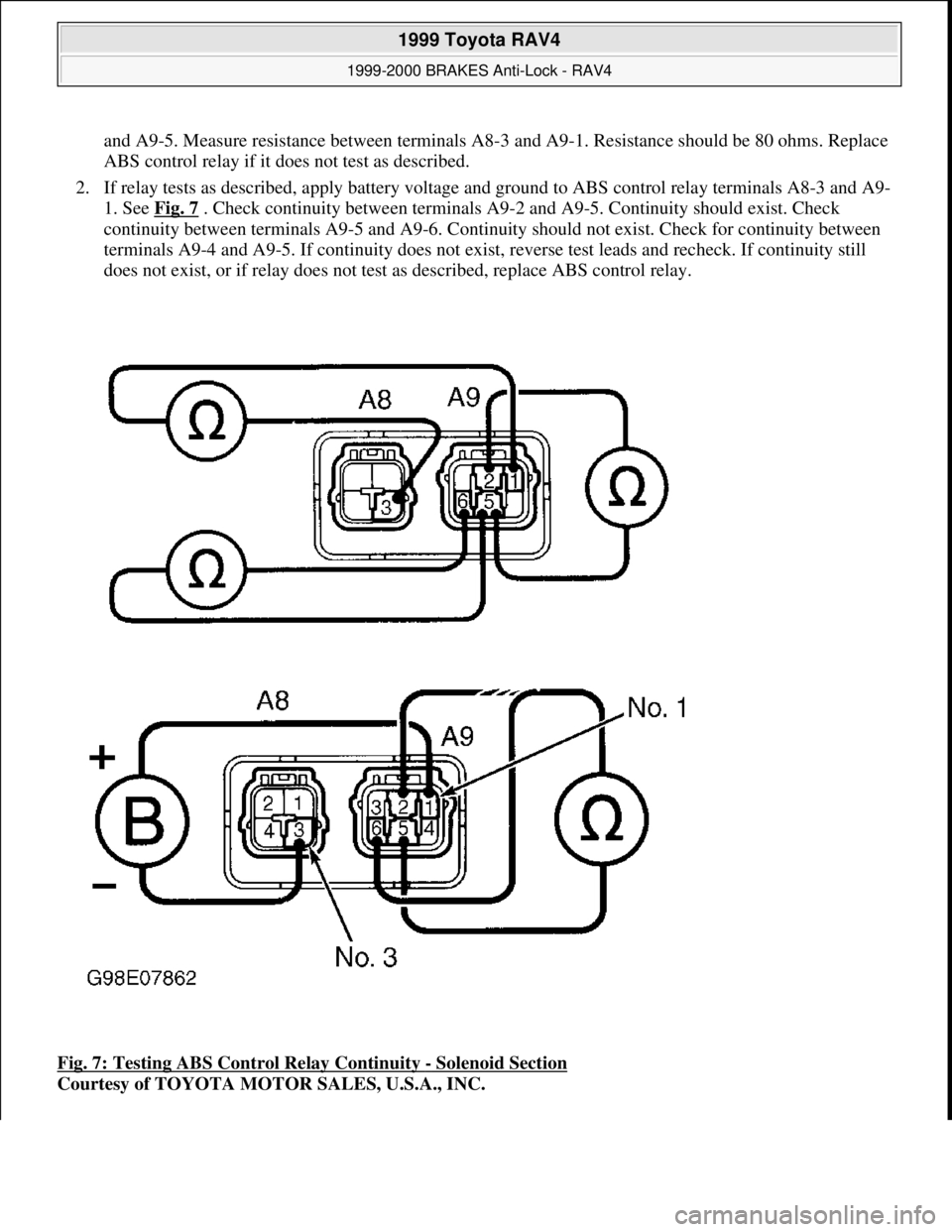
and A9-5. Measure resistance between terminals A8-3 and A9-1. Resistance should be 80 ohms. Replace
ABS control relay if it does not test as described.
2. If relay tests as described, apply battery voltage and ground to ABS control relay terminals A8-3 and A9-
1. See Fig. 7
. Check continuity between terminals A9-2 and A9-5. Continuity should exist. Check
continuity between terminals A9-5 and A9-6. Continuity should not exist. Check for continuity between
terminals A9-4 and A9-5. If continuity does not exist, reverse test leads and recheck. If continuity still
does not exist, or if relay does not test as described, replace ABS control relay.
Fig. 7: Testing ABS Control Relay Continuity
- Solenoid Section
Courtesy of TOYOTA MOTOR SALES, U.S.A., INC.
1999 Toyota RAV4
1999-2000 BRAKES Anti-Lock - RAV4
Microsoft
Sunday, November 22, 2009 10:06:17 AMPage 20 © 2005 Mitchell Repair Information Company, LLC.