bulb TOYOTA RAV4 1996 Service Repair Manual
[x] Cancel search | Manufacturer: TOYOTA, Model Year: 1996, Model line: RAV4, Model: TOYOTA RAV4 1996Pages: 1632, PDF Size: 41.64 MB
Page 1 of 1632
1999-2000 BRAKES
Anti-Lock - RAV4
DESCRIPTION
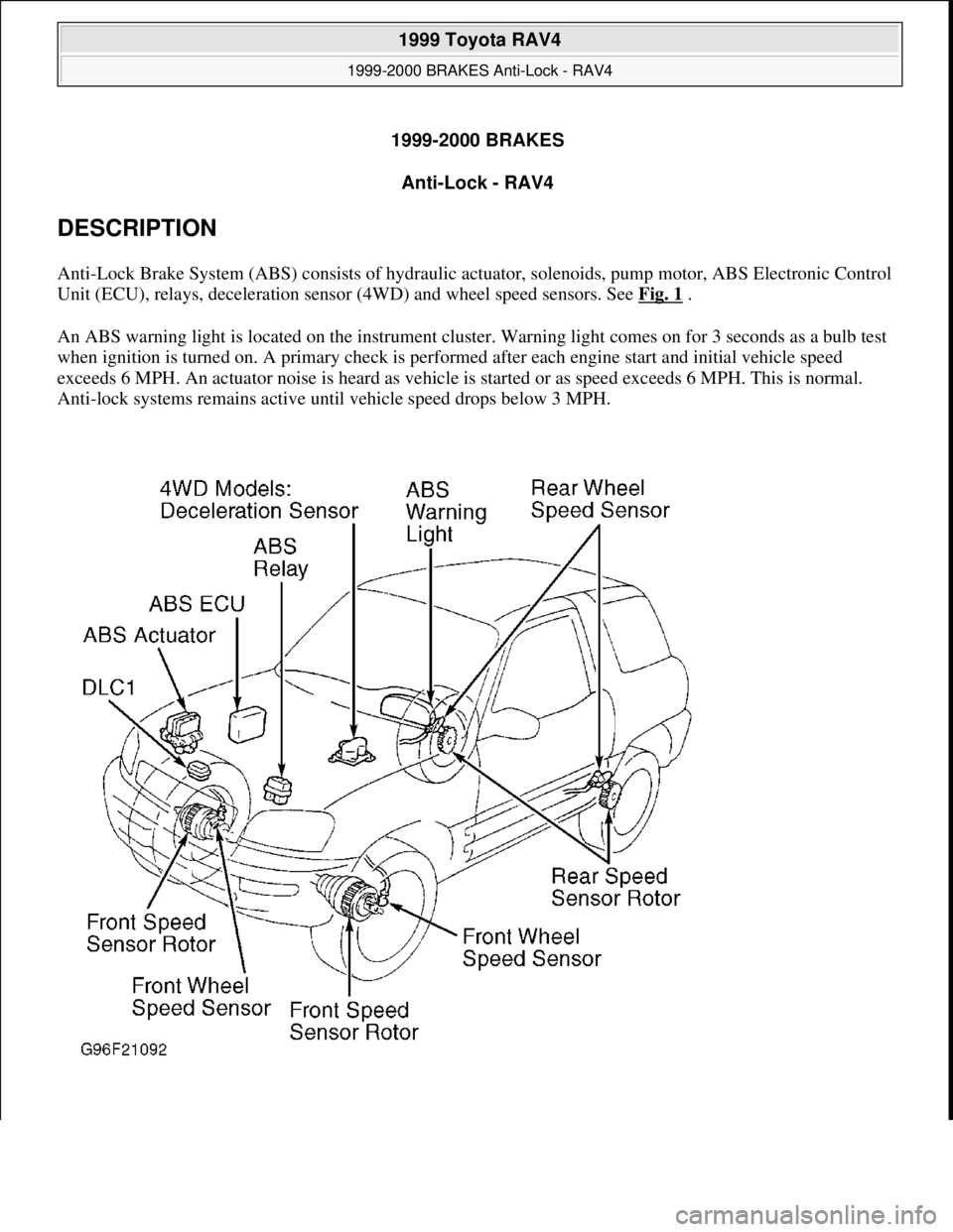
Anti-Lock Brake System (ABS) consists of hydraulic actuator, solenoids, pump motor, ABS Electronic Control
Unit (ECU), relays, deceleration sensor (4WD) and wheel speed sensors. See Fig. 1
.
An ABS warning light is located on the instrument cluster. Warning light comes on for 3 seconds as a bulb test
when ignition is turned on. A primary check is performed after each engine start and initial vehicle speed
exceeds 6 MPH. An actuator noise is heard as vehicle is started or as speed exceeds 6 MPH. This is normal.
Anti-lock systems remains active until vehicle speed drops below 3 MPH.
1999 Toyota RAV4
1999-2000 BRAKES Anti-Lock - RAV4
1999 Toyota RAV4
1999-2000 BRAKES Anti-Lock - RAV4
Microsoft
Sunday, November 22, 2009 10:06:17 AMPage 1 © 2005 Mitchell Repair Information Company, LLC.
Microsoft
Sunday, November 22, 2009 10:06:21 AMPage 1 © 2005 Mitchell Repair Information Company, LLC.
Page 3 of 1632
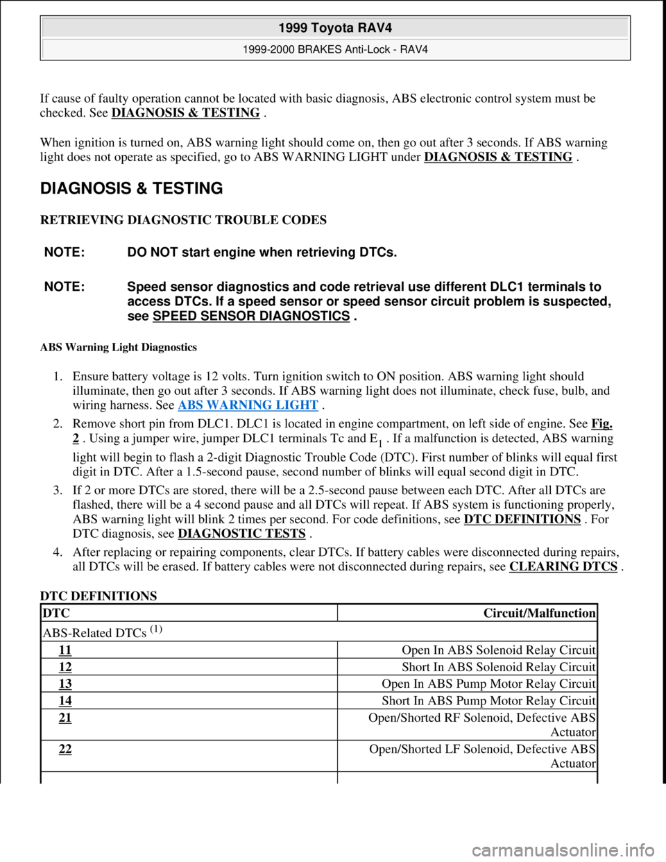
If cause of faulty operation cannot be located with basic diagnosis, ABS electronic control system must be
checked. See DIAGNOSIS & TESTING
.
When ignition is turned on, ABS warning light should come on, then go out after 3 seconds. If ABS warning
light does not operate as specified, go to ABS WARNING LIGHT under DIAGNOSIS & TESTING
.
DIAGNOSIS & TESTING
RETRIEVING DIAGNOSTIC TROUBLE CODES
ABS Warning Light Diagnostics
1. Ensure battery voltage is 12 volts. Turn ignition switch to ON position. ABS warning light should
illuminate, then go out after 3 seconds. If ABS warning light does not illuminate, check fuse, bulb, and
wiring harness. See ABS WARNING LIGHT
.
2. Remove short pin from DLC1. DLC1 is located in engine compartment, on left side of engine. See Fig.
2 . Using a jumper wire, jumper DLC1 terminals Tc and E1 . If a malfunction is detected, ABS warning
light will begin to flash a 2-digit Diagnostic Trouble Code (DTC). First number of blinks will equal first
digit in DTC. After a 1.5-second pause, second number of blinks will equal second digit in DTC.
3. If 2 or more DTCs are stored, there will be a 2.5-second pause between each DTC. After all DTCs are
flashed, there will be a 4 second pause and all DTCs will repeat. If ABS system is functioning properly,
ABS warning light will blink 2 times per second. For code definitions, see DTC DEFINITIONS
. For
DTC diagnosis, see DIAGNOSTIC TESTS
.
4. After replacing or repairing components, clear DTCs. If battery cables were disconnected during repairs,
all DTCs will be erased. If battery cables were not disconnected during repairs, see CLEARING DTCS
.
DTC DEFINITIONS NOTE: DO NOT start engine when retrieving DTCs.
NOTE: Speed sensor diagnostics and code retrieval use different DLC1 terminals to
access DTCs. If a speed sensor or speed sensor circuit problem is suspected,
see SPEED SENSOR DIAGNOSTICS
.
DTCCircuit/Malfunction
ABS-Related DTCs (1)
11 Open In ABS Solenoid Relay Circuit
12 Short In ABS Solenoid Relay Circuit
13 Open In ABS Pump Motor Relay Circuit
14 Short In ABS Pump Motor Relay Circuit
21 Open/Shorted RF Solenoid, Defective ABS
Actuator
22 Open/Shorted LF Solenoid, Defective ABS
Actuator
1999 Toyota RAV4
1999-2000 BRAKES Anti-Lock - RAV4
Microsoft
Sunday, November 22, 2009 10:06:17 AMPage 3 © 2005 Mitchell Repair Information Company, LLC.
Page 5 of 1632
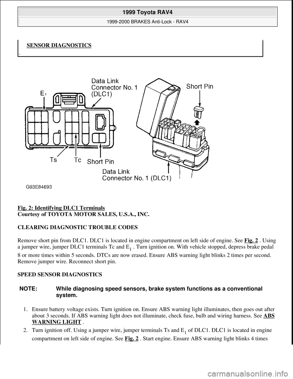
Fig. 2: Identifying DLC1 Terminals
Courtesy of TOYOTA MOTOR SALES, U.S.A., INC.
CLEARING DIAGNOSTIC TROUBLE CODES
Remove short pin from DLC1. DLC1 is located in engine compartment on left side of engine. See Fig. 2
. Using
a jumper wire, jumper DLC1 terminals Tc and E
1 . Turn ignition on. With vehicle stopped, depress brake pedal
8 or more times within 5 seconds. DTCs are now erased. Ensure ABS warning light blinks 2 times per second.
Remove jumper wire. Reconnect short pin.
SPEED SENSOR DIAGNOSTICS
1. Ensure battery voltage exists. Turn ignition on. Ensure ABS warning light illuminates, then goes out after
about 3 seconds. If ABS warning light does not illuminate, check fuse, bulb and wiring harness. See ABS
WARNING LIGHT .
2. Turn ignition off. Using a jumper wire, jumper terminals Ts and E
1 of DLC1. DLC1 is located in engine
compartment on left side of en
gine. See Fig. 2. Start engine. Ensure ABS warning light blinks 4 times
.SENSOR DIAGNOSTICS
NOTE: While diagnosing speed sensors, brake system functions as a conventional
system.
1999 Toyota RAV4
1999-2000 BRAKES Anti-Lock - RAV4
Microsoft
Sunday, November 22, 2009 10:06:17 AMPage 5 © 2005 Mitchell Repair Information Company, LLC.
Page 6 of 1632
per second. If ABS light does not blink, go to ABS WARNING LIGHT. If ABS warning light blinks,
go to next step.
3. Drive vehicle straight ahead above 28 MPH for several seconds. Stop vehicle. Jumper terminals Tc and
E
1 of DLC1. See Fig. 2 . If all sensors are okay, a normal DTC is displayed (ABS warning light blinks 2
times a second). If a malfunction is detected, ABS warning light will begin to flash a 2-digit DTC. First
number of blinks will equal first digit in a DTC. After a 1.5-second pause, second number of blinks will
equal second digit in a DTC.
4. If 2 or more DTCs are stored, there will be a 2.5-second pause between each DTC. After all DTCs are
flashed, there will be a 4 second pause and all DTCs will repeat.
5. Record DTCs. Turn ignition off. Repair as necessary. See DTC DEFINITIONS
. Remove jumper wire
from DLC1. Clear DTCs. See CLEARING DTCS
.
ABS WARNING LIGHT
Circuit Description
If ABS ECU detects a system malfunction, ABS ECU illuminates ABS warning light while at the same time
prohibiting ABS control. At this time, ABS ECU records a DTC in memory. After removing short pin from
DLC1, connecting terminals Tc and E
1 of DLC1 causes ABS warning light to blink and output a DTC. See Fig.
2 .
Diagnostic Procedure
1. If ABS warning light stays on, go to step 3 . If ABS warning light does not illuminate, check fuse, light
bulb and wiring. Repair or replace as necessary. If bulb is okay, diagnose combination meter (instrument
panel). See appropriate INSTRUMENT PANELS article in ACCESSORIES & EQUIPMENT. If no
problems were found, go to next step.
2. Check ABS control relay. See SOLENOID RELAY SECTION
under ABS CONTROL RELAY under
COMPONENT TESTS. Replace as necessary. If ABS control relay is okay, go to next step.
3. Retrieve DTCs. See RETRIEVING DTCS
under DIAGNOSIS & TESTING. If DTC is present, perform
appropriate test under DIAGNOSTIC TESTS. If DTC is not present, and ABS warning light goes off
when short pin is removed, go to next step. If ABS warning light does not turn off, check for short circuit
in wiring harness between ABS warning light, DLC1 and ABS ECU. Repair as necessary. See WIRING
DIAGRAMS .
4. Check ABS control relay. See SOLENOID RELAY SECTION
under ABS CONTROL RELAY under
COMPONENT TESTS. Replace relay as necessary. If relay is okay, check for short circuit in wiring
harness between DLC1 and ABS control relay. Repair as necessary. See WIRING DIAGRAMS
.
TC TERMINAL
Circuit Description
Connecting terminals Tc and E1 of DLC1 causes ABS warning light to blink and output a DTC. See Fig. 2 .
Diagnostic Procedure
1999 Toyota RAV4
1999-2000 BRAKES Anti-Lock - RAV4
Microsoft
Sunday, November 22, 2009 10:06:17 AMPage 6 © 2005 Mitchell Repair Information Company, LLC.
Page 26 of 1632
1. Check charging system voltage. Ensure 10-14 volts is present. If charging system voltage is okay, go to
next step. If charging system voltage is not okay, check and repair charging system.
2. Turn ignition switch to ON position. Ensure ABS warning light comes on, then goes out after 3 seconds.
If ABS warning light does not illuminate, check fuse, bulb, and wiring harness. See ABS WARNING
LIGHT under DIAGNOSIS & TESTING. Turn ignition off.
3. Using a jumper wire, jumper terminals Ts and E
1 of DLC1. DLC1 is located in engine compartment on
left side of engine. See Fig. 2
. Ensure ABS warning light blinks 4 times per second. If ABS light does
not blink, go to ABS WARNING LIGHT
under DIAGNOSIS & TESTING. If ABS warning light
blinks, go to next step.
4. Using a floor jack, slowly jack up rear of vehicle. On vehicles with 215/70R16 tires, raise vehicle to a
height of 25.59-27.95" (650-710 mm). On vehicles with 235/60R16 tires, raise vehicle to a height of
26.38-28.74" (670-730 mm). If ABS warning light illuminates at specified height, check deceleration
sensor installation. If installation is okay, replace deceleration sensor. Lower vehicle.
5. Using a floor jack, slowly jack up front of vehicle. On vehicles with 215/70R16 tires, raise vehicle to a
height of 21.20-23.56" (550-610 mm). On vehicles with 235/60R16 tires, raise vehicle to a height of
22.44-24.80" (570-630 mm). If ABS warning light illuminates at specified height, check deceleration
sensor installation. If installation is okay, replace deceleration sensor. Lower vehicle.
6. Drive vehicle straight ahead at speed of 13 MPH or more. Lightly depress brake pedal. Ensure ABS
warning light pattern is normal (light blinks 4 times per second).
7. While driving vehicle straight ahead at speed of 13 MPH or more, moderately depress brake pedal.
Ensure ABS warning light illuminates in a solid pattern (light does not blink) while braking.
8. While driving vehicle straight ahead at speed of 13 MPH or more, firmly depress brake pedal. Ensure
ABS warning light illumination pattern changes from a solid pattern (light does not blink) to a normal
pattern (light blinks 4 times per second), then back to a solid pattern while braking.
9. If ABS warning light does not illuminate as described in steps 6 -8 , check deceleration sensor
installation. If installation is okay, replace deceleration sensor. Stop vehicle and turn ignition off. Remove
jumper wire from DLC1.
REMOVAL & INSTALLATION
ACTUATOR
Removal & Installation
Turn ignition off. Disconnect brakelines attached to actuator. Remove power steering hose retaining bracket
bolt and power steering reservoir. Disconnect actuator electrical connectors. Remove bolts, nuts and washers.
Remove actuator assembly. Remove actuator from actuator bracket. Remove cushions and holders from NOTE: When measuring vehicle height in following steps, measure at center of
lower body of vehicle.
WARNING:Hydraulic system may be under high pressure. Use caution when opening
hydraulic system.
1999 Toyota RAV4
1999-2000 BRAKES Anti-Lock - RAV4
Microsoft
Sunday, November 22, 2009 10:06:17 AMPage 26 © 2005 Mitchell Repair Information Company, LLC.
Page 37 of 1632
The air bag sensor, which deploys air bags, contains a back-up power supply, safing sensor and diagnostic code
memory. Spiral cable (clockspring) maintains a complete circuit to the steering wheel pad.
SYSTEM OPERATION CHECK
Turn ignition switch to ACC or ON position. Air bag warning light in instrument cluster should come on for
about 6 seconds and then go out. If light does not respond as specified, SRS is malfunctioning and needs repair.
See DIAGNOSIS
.
SERVICE PRECAUTIONS
Observe the following precautions when working on SRS:
Before servicing any SRS or steering column component, disable SRS. See DISABLING &
ACTIVATING AIR BAG SYSTEM . Failure to disable system could result in accidental air bag
deployment and personal injury.
When diagnosing SRS, always check for diagnostic codes before disconnecting battery.
After ignition switch is turned to LOCK position and negative battery cable is disconnected, wait at least
90 seconds before working on SRS. SRS is equipped with a back-up power source that may allow air bag
to deploy within 90 seconds of disconnecting negative battery cable.
In a minor collision in which air bags do not deploy, steering wheel pad must be inspected.
NEVER use air bag parts from another vehicle. Replace air bag parts with new parts.
Air bag sensor assembly contains mercury. After replacement, DO NOT destroy the old part. When
scrapping vehicle or replacing air bag sensor assembly, remove air bag sensor assembly and dispose of as
toxic waste.
Never disassemble or repair system components. Replace cracked, dented or otherwise damaged system
components.
Remove air bag sensor if shocks are likely to be applied to the sensor during repairs.
When diagnosing electrical circuits, use a Digital Volt/Ohmmeter (DVOM) with high impedance (10,000
ohms minimum).
Information labels are attached to air bag components. Follow all notices on labels.
After servicing SRS, check air bag warning light to ensure system is functioning properly. See SYSTEM
OPERATION CHECK .
Always wear safety glasses when servicing or handling an air bag.
When placing a live air bag on a bench or other surface, always face air bag and trim cover up, away from
surface. This will reduce motion of module if accidentally deployed.
After deployment, air bag surface may contain deposits of sodium hydroxide which irritates skin. During
clean-up, always wear safety glasses, rubber gloves and long-sleeved shirt. After clean-up, wash hands
using mild soap and water.
When carrying a live air bag module, trim cover must be pointed away from your body to minimize
injury in case of accidental deployment.
If SRS is not fully functional for any reason, vehicle should not be driven until system is repaired and
a
gain becomes operational. DO NOTremove bulbs, modules, sensors or other components or in any way
1996 Toyota 4Runner
AIR BAG RESTRAINT SYSTEM 1996 ACCESSORIES/SAFETY EQUIPMENT Toyota Air Bag Restraint System
Microsoft
Tuesday, August 18, 2009 7:33:32 PMPage 3 © 2005 Mitchell Repair Information Company, LLC.
Page 52 of 1632
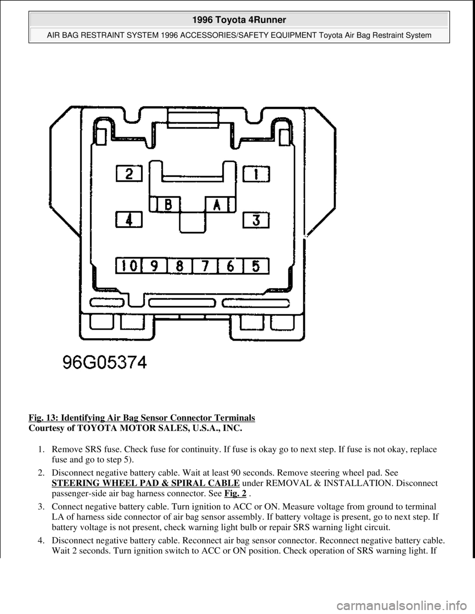
Fig. 13: Identifying Air Bag Sensor Connector Terminals
Courtesy of TOYOTA MOTOR SALES, U.S.A., INC.
1. Remove SRS fuse. Check fuse for continuity. If fuse is okay go to next step. If fuse is not okay, replace
fuse and go to step 5).
2. Disconnect negative battery cable. Wait at least 90 seconds. Remove steering wheel pad. See
STEERING WHEEL PAD & SPIRAL CABLE
under REMOVAL & INSTALLATION. Disconnect
passenger-side air bag harness connector. See Fig. 2
.
3. Connect negative battery cable. Turn ignition to ACC or ON. Measure voltage from ground to terminal
LA of harness side connector of air bag sensor assembly. If battery voltage is present, go to next step. If
battery voltage is not present, check warning light bulb or repair SRS warning light circuit.
4. Disconnect negative battery cable. Reconnect air bag sensor connector. Reconnect negative battery cable.
Wait 2 seconds. Turn i
gnition switch to ACC or ON position. Check operation of SRS warning light. If
1996 Toyota 4Runner
AIR BAG RESTRAINT SYSTEM 1996 ACCESSORIES/SAFETY EQUIPMENT Toyota Air Bag Restraint System
Microsoft
Tuesday, August 18, 2009 7:33:32 PMPage 18 © 2005 Mitchell Repair Information Company, LLC.
Page 66 of 1632
may allow air bag to deploy until 90 seconds after disconnecting negative battery cable.
If vehicle was in a minor collision but air bags did not deploy, inspect all system components for any sign
of damage, and replace as necessary.
Never use air bag system components from another vehicle. Replace air bag system components with new
parts.
Remove air bag sensor assembly if repairing the vehicle requires impacting (shocking) the vehicle.
Air bag sensor assembly contains mercury. After replacement, DO NOT destroy old part. When
scrapping vehicle or replacing air bag sensor assembly, remove air bag sensor assembly and dispose of it
as toxic waste.
Never disassemble and repair air bag sensor assembly, front air bag sensors, passenger-side or driver-side
air bag modules or seat belt pretensioners.
Replace dropped, cracked, dented or otherwise damaged components.
DO NOT expose air bag sensor assembly, front air bag sensors or air bag modules directly to heat or
flame.
When diagnosing electrical circuits, use a volt/ohm meter with high impedance (10,000 ohms minimum).
Information labels are attached to air bag components. Follow all notices on labels.
After work on air bag system is complete, check AIR BAG warning light to ensure system is functioning
properly. See SYSTEM OPERATION CHECK
.
Always wear safety glasses when servicing or handling an air bag.
When placing a live air bag on a bench or other surface, always face air bag and trim cover up and away
from surface. This will reduce motion of module if it is accidentally deployed.
After deployment, air bag surface may contain deposits of sodium hydroxide, which irritates skin. Always
wear safety glasses, rubber gloves, and long-sleeved shirt during clean-up. After clean-up, wash hands
using mild soap and water.
Carry a live air bag module with trim cover (air bag) pointed away from your body to minimize injury in
case accidental deployment.
If air bag system is not fully functional for any reason, vehicle should not be driven until system is
repaired and again becomes operational. DO NOT remove bulbs, modules, sensors or other components,
or in any way disable system from operating normally. If air bag system is not functional, park vehicle
until it is repaired and functions properly.
ADJUSTMENTS
SPIRAL CABLE
Ensure front wheels are in straight-ahead position. Turn spiral cable counterclockwise until it becomes difficult
to turn. Turn spiral cable clockwise about 2 1/2 turns to align match marks. See Fig. 2
. Install steering wheel.
1999 Toyota RAV4
AIR BAG RESTRAINT SYSTEM 1999 Toyota
Microsoft
Sunday, November 22, 2009 10:33:22 AMPage 3 © 2005 Mitchell Repair Information Company, LLC.
Page 88 of 1632
Fig. 15: Releasing Shorting Spring
Courtesy of TOYOTA MOTOR SALES, U.S.A., INC.
DIAGNOSTIC TESTS
AIR BAG WARNING LIGHT DOES NOT ILLUMINATE
Description
AIR BAG warning light is located in instrument cluster. When air bag system is normal, AIR BAG warning
light illuminates for about 6 seconds after ignition switch is turned from LOCK to ACC or ON position, and
turns off automatically. If a malfunction is present in air bag system, AIR BAG warning light illuminates to
inform operator of malfunction. When Data Link Connector 1 (DLC1) terminals Tc and E1 are connected
together, a Diagnostic Trouble Code (DTC) is displayed by flashing AIR BAG warning light.
Diagnostic Procedure
1. Remove SRS-B fuse and check continuity across fuse blades. SRS-B fuse is located in instrument panel
fuse block under left side of instrument panel. If fuse is faulty, go to step 4). If fuse is okay, reinstall fuse
and go to next step.
2. Disable air bag system. See DISABLING SYSTEM
under DISABLING & ACTIVATING AIR BAG
SYSTEM. Reconnect negative battery cable. Turn ignition switch to ACC or ON position. Measure
voltage between ground and harness side of air bag sensor assembly connector C20, terminal No. 3
(circuit LA, Black/Yellow wire). See Fig. 16
. If 10-14 volts is not present, repair AIR BAG warning
light bulb or circuit. If 10-14 volts is present, go to next step.
3. Turn ignition switch to LOCK position. Disconnect negative battery cable. Reconnect 3 air bag sensor
assembly connectors. Leave air bag modules, pretensioners and front air bag sensors disconnected.
Reconnect negative battery cable and wait at least 2 seconds. Turn ignition switch to ACC or ON
position. If AIR BAG warning light illuminates, system operation is normal. If AIR BAG warning light
does not come on, check for poor connection at air bag sensor assembly connector C20, terminal No. 3
(Black/Yellow wire). If connection is oka
y, replace air bag sensor assembly. WARNING:Failure to follow service precautions may result in air bag deployment and
personal injury. See SERVICE PRECAUTIONS
. After component
replacement, check system operation. See SYSTEM OPERATION CHECK
.
CAUTION: Ensure ignition switch is in LOCK position before disconnecting or
connecting negative battery cable. If ignition switch is in ACC or ON
position when negative battery cable is disconnected or connected, air
bag sensor may be damaged. To prevent damage to connector terminals,
DO NOT probe terminal ends. Instead, backprobe terminals (probe
terminal where wire enters harness connector).
NOTE: In the following tests, the term squib connector and module connector may be
used interchangeably.
1999 Toyota RAV4
AIR BAG RESTRAINT SYSTEM 1999 Toyota
Microsoft
Sunday, November 22, 2009 10:33:23 AMPage 25 © 2005 Mitchell Repair Information Company, LLC.
Page 388 of 1632
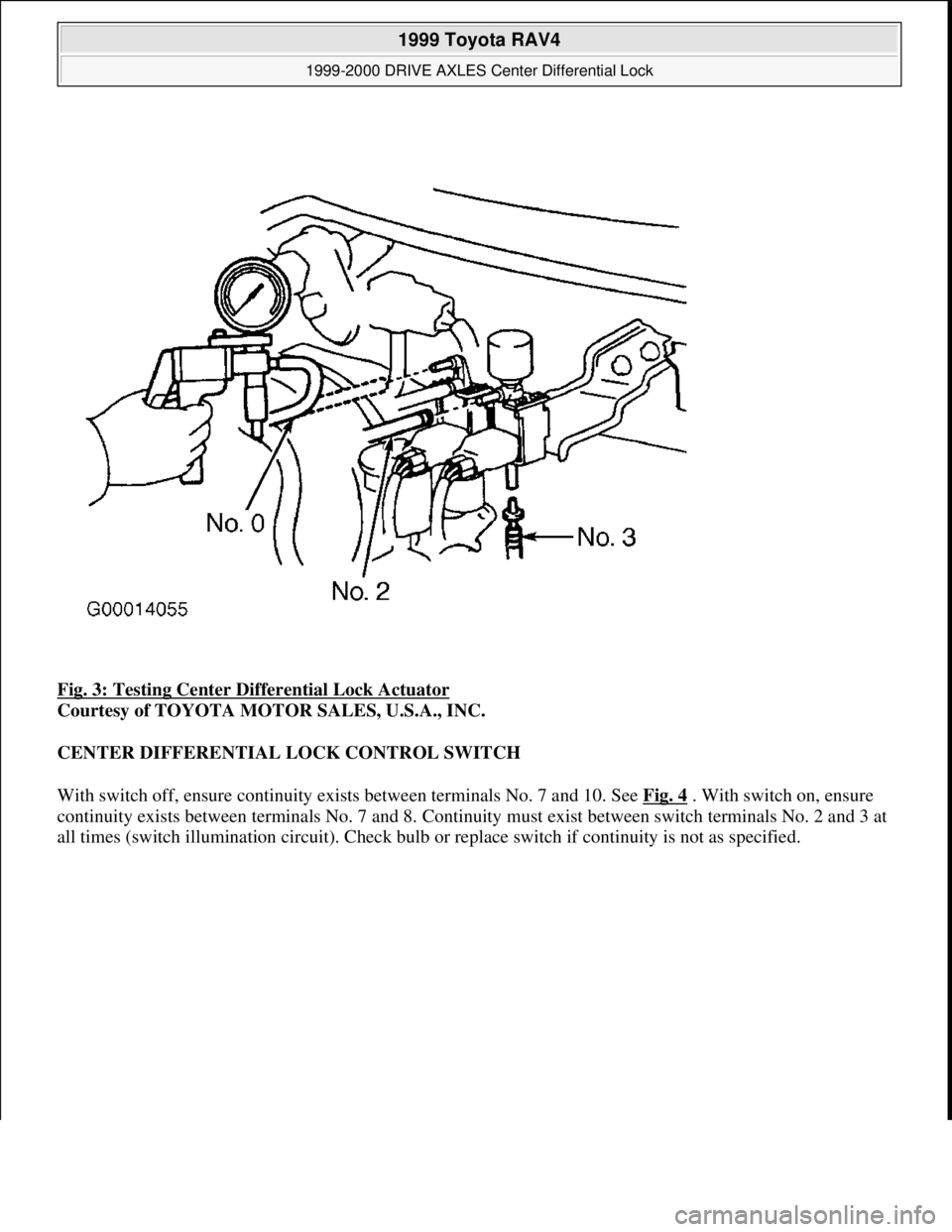
Fig. 3: Testing Center Differential Lock Actuator
Courtesy of TOYOTA MOTOR SALES, U.S.A., INC.
CENTER DIFFERENTIAL LOCK CONTROL SWITCH
With switch off, ensure continuity exists between terminals No. 7 and 10. See Fig. 4
. With switch on, ensure
continuity exists between terminals No. 7 and 8. Continuity must exist between switch terminals No. 2 and 3 at
all times (switch illumination circuit). Check bulb or replace switch if continuit
y is not as specified.
1999 Toyota RAV4
1999-2000 DRIVE AXLES Center Differential Lock
Microsoft
Sunday, November 22, 2009 10:08:59 AMPage 5 © 2005 Mitchell Repair Information Company, LLC.