change wheel TOYOTA RAV4 1996 Service Repair Manual
[x] Cancel search | Manufacturer: TOYOTA, Model Year: 1996, Model line: RAV4, Model: TOYOTA RAV4 1996Pages: 1632, PDF Size: 41.64 MB
Page 15 of 1632
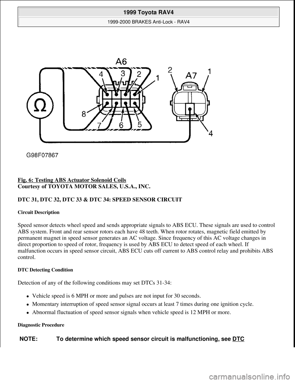
Fig. 6: Testing ABS Actuator Solenoid Coils
Courtesy of TOYOTA MOTOR SALES, U.S.A., INC.
DTC 31, DTC 32, DTC 33 & DTC 34: SPEED SENSOR CIRCUIT
Circuit Description
Speed sensor detects wheel speed and sends appropriate signals to ABS ECU. These signals are used to control
ABS system. Front and rear sensor rotors each have 48 teeth. When rotor rotates, magnetic field emitted by
permanent magnet in speed sensor generates an AC voltage. Since frequency of this AC voltage changes in
direct proportion to speed of rotor, frequency is used by ABS ECU to detect speed of each wheel. If
malfunction occurs in speed sensor circuit, ABS ECU cuts off current to ABS control relay and prohibits ABS
control.
DTC Detecting Condition
Detection of any of the following conditions may set DTCs 31-34:
Vehicle speed is 6 MPH or more and pulses are not input for 30 seconds.
Momentary interruption of speed sensor signal occurs at least 7 times during one ignition cycle.
Abnormal fluctuation of speed sensor signals when vehicle speed is 12 MPH or more.
Diagnostic Procedure
NOTE: To determine which speed sensor circuit is malfunctioning, see DTC
1999 Toyota RAV4
1999-2000 BRAKES Anti-Lock - RAV4
Microsoft
Sunday, November 22, 2009 10:06:17 AMPage 15 © 2005 Mitchell Repair Information Company, LLC.
Page 17 of 1632
DTC Detecting Condition
Detection of the following condition may set DTC 41:
At vehicle speed of about 2 MPH or more, if voltage at ABS ECU terminal IG1 is less than 9.5 volts for
10 seconds or more, DTC 41 may set.
Diagnostic Procedure
1. Check charging system voltage. If voltage is 10-14 volts, system is okay. Go to next step. If voltage is not
10-14 volts, repair charging system. Ensure system fuses are okay.
2. Turn ignition off. Remove ABS ECU. Do not disconnect electrical connectors. Turn ignition switch to
ON position. Measure voltage between terminals IG1 and GND at ABS ECU harness connector. See Fig.
3 . If voltage is 10-14 volts, turn ignition off. Condition may be intermittent. Check ABS ECU connectors
for poor connection or damage. Repair as necessary. If connectors are okay, replace ABS ECU. If voltage
is not as specified, go to next step.
3. Measure resistance between ground and GND terminals at ABS ECU harness connector. See Fig. 3
. If
resistance is one ohm or less, go to next step. If resistance is more than one ohm, repair ground circuit
wiring. See WIRING DIAGRAMS
.
4. Remove ECU-IG fuse from instrument panel junction block. If fuse is blown, check for short circuit in all
wiring harnesses and components connected to ECU-IG fuse (ECM, A/C, cruise control, deceleration
sensor, combination meter, sun roof, shift lock, transmission pattern select switch). See WIRING
DIAGRAMS . Repair as necessary. If fuse is not blown, check for open circuit in wiring harness between
battery and ABS ECU. Repair as necessary.
DTC 43 & DTC 45: DECELERATION SENSOR MALFUNCTION (4WD MODELS ONLY)
DTC Detecting Conditions
Detection of the following conditions may set DTCs 43 or 45:
On 2-door models, if output voltage from deceleration sensor does not change for 16 consecutive times or
more when vehicle speed is decreased from 19 MPH to zero MPH, DTC 43 will set.
On 4-door models, after battery cables are connected, if input from deceleration sensor does not change at
one cycle (zero MPH to 19 MPH or more, then back to zero) for 16 consecutive times, DTC 43 will set.
When brake pedal is not depressed at vehicle speed of 3 MPH or more, and forward and backward force
(force of more than 0.4 "G") is detected for 30 seconds or more, DTC 43 will set.
On 2-door models, at vehicle speed of 19 MPH or more, if deceleration sensor output and vehicle
acceleration from wheel speed remains abnormally different for one minute or more, DTC 45 will set.
Diagnostic Procedure
1. Check deceleration sensor. See DECELERATION SENSOR CHECK under COMPONENT TESTS.
Replace sensor as necessary. If sensor is okay, go to next step.
2. Check for open or short circuit in wiring harness between deceleration sensor and ABS ECU. See
WIRING DIAGRAMS
. Repair as necessary. If wiring harness is okay, replace ABS ECU.
1999 Toyota RAV4
1999-2000 BRAKES Anti-Lock - RAV4
Microsoft
Sunday, November 22, 2009 10:06:17 AMPage 17 © 2005 Mitchell Repair Information Company, LLC.
Page 344 of 1632
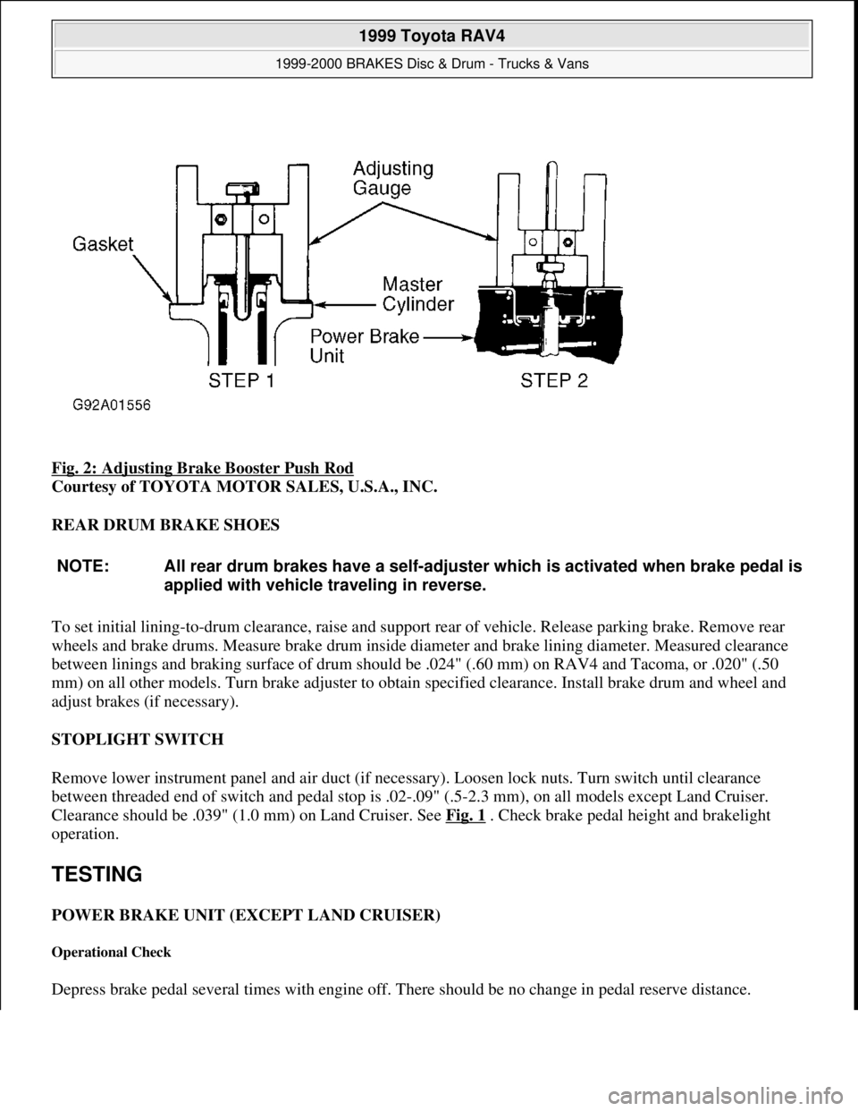
Fig. 2: Adjusting Brake Booster Push Rod
Courtesy of TOYOTA MOTOR SALES, U.S.A., INC.
REAR DRUM BRAKE SHOES
To set initial lining-to-drum clearance, raise and support rear of vehicle. Release parking brake. Remove rear
wheels and brake drums. Measure brake drum inside diameter and brake lining diameter. Measured clearance
between linings and braking surface of drum should be .024" (.60 mm) on RAV4 and Tacoma, or .020" (.50
mm) on all other models. Turn brake adjuster to obtain specified clearance. Install brake drum and wheel and
adjust brakes (if necessary).
STOPLIGHT SWITCH
Remove lower instrument panel and air duct (if necessary). Loosen lock nuts. Turn switch until clearance
between threaded end of switch and pedal stop is .02-.09" (.5-2.3 mm), on all models except Land Cruiser.
Clearance should be .039" (1.0 mm) on Land Cruiser. See Fig. 1
. Check brake pedal height and brakelight
operation.
TESTING
POWER BRAKE UNIT (EXCEPT LAND CRUISER)
Operational Check
Depress brake pedal several times with engine off. There should be no change in pedal reserve distance.
NOTE: All rear drum brakes have a self-adjuster which is activated when brake pedal is
applied with vehicle traveling in reverse.
1999 Toyota RAV4
1999-2000 BRAKES Disc & Drum - Trucks & Vans
Microsoft
Sunday, November 22, 2009 10:07:28 AMPage 5 © 2005 Mitchell Repair Information Company, LLC.
Page 347 of 1632
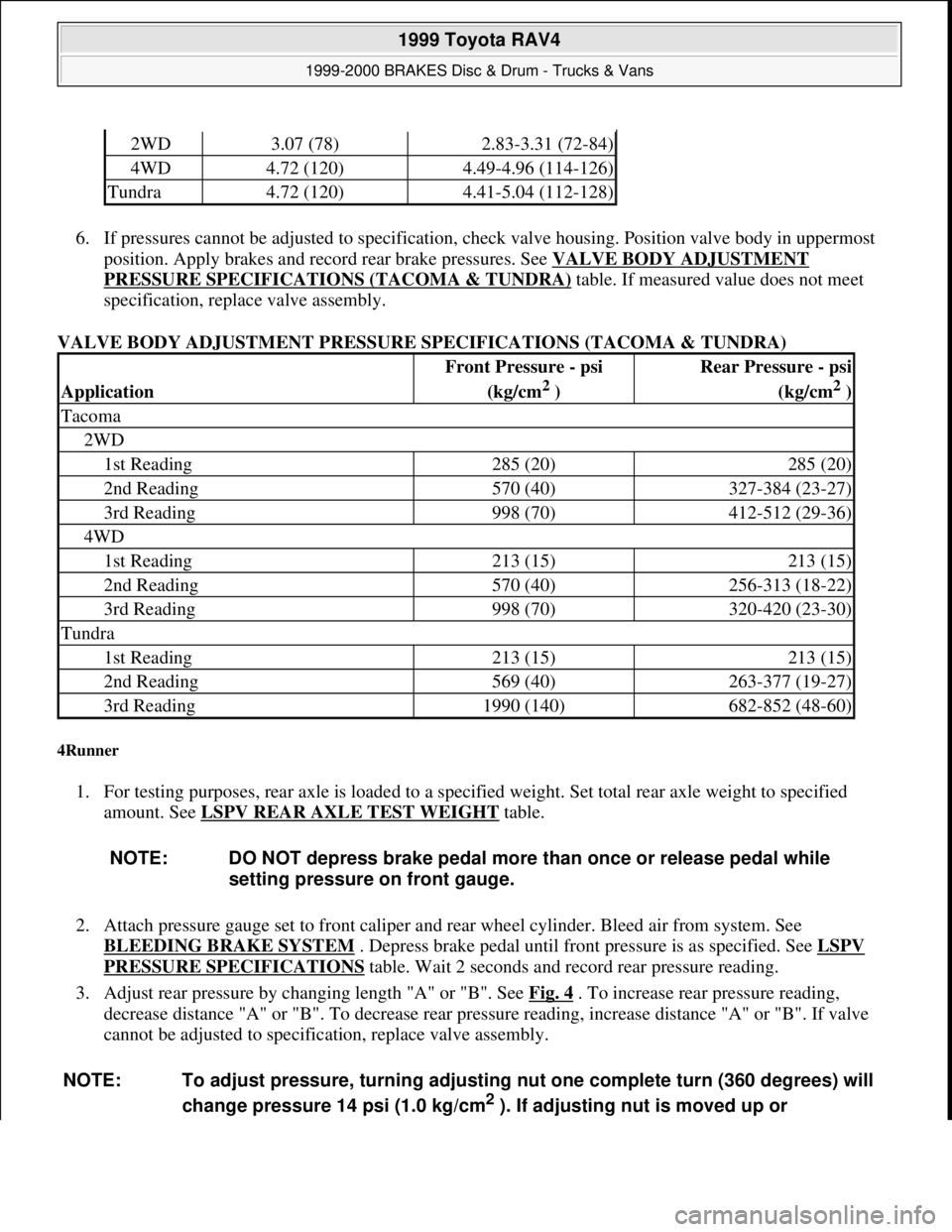
6. If pressures cannot be adjusted to specification, check valve housing. Position valve body in uppermost
position. Apply brakes and record rear brake pressures. See VALVE BODY ADJUSTMENT
PRESSURE SPECIFICATIONS (TACOMA & TUNDRA) table. If measured value does not meet
specification, replace valve assembly.
VALVE BODY ADJUSTMENT PRESSURE SPECIFICATIONS (TACOMA & TUNDRA)
4Runner
1. For testing purposes, rear axle is loaded to a specified weight. Set total rear axle weight to specified
amount. See LSPV REAR AXLE TEST WEIGHT
table.
2. Attach pressure gauge set to front caliper and rear wheel cylinder. Bleed air from system. See
BLEEDING BRAKE SYSTEM
. Depress brake pedal until front pressure is as specified. See LSPV
PRESSURE SPECIFICATIONS table. Wait 2 seconds and record rear pressure reading.
3. Adjust rear pressure by changing length "A" or "B". See Fig. 4
. To increase rear pressure reading,
decrease distance "A" or "B". To decrease rear pressure reading, increase distance "A" or "B". If valve
cannot be adjusted to specification, replace valve assembly.
2WD3.07 (78)2.83-3.31 (72-84)
4WD4.72 (120)4.49-4.96 (114-126)
Tundra4.72 (120)4.41-5.04 (112-128)
Application
Front Pressure - psi
(kg/cm
2 )
Rear Pressure - psi
(kg/cm
2 )
Tacoma
2WD
1st Reading285 (20)285 (20)
2nd Reading570 (40)327-384 (23-27)
3rd Reading998 (70)412-512 (29-36)
4WD
1st Reading213 (15)213 (15)
2nd Reading570 (40)256-313 (18-22)
3rd Reading998 (70)320-420 (23-30)
Tundra
1st Reading213 (15)213 (15)
2nd Reading569 (40)263-377 (19-27)
3rd Reading1990 (140)682-852 (48-60)
NOTE: DO NOT depress brake pedal more than once or release pedal while
setting pressure on front gauge.
NOTE: To adjust pressure, turning adjusting nut one complete turn (360 degrees) will
change pressure 14 psi (1.0 kg/cm
2 ). If adjusting nut is moved up or
1999 Toyota RAV4
1999-2000 BRAKES Disc & Drum - Trucks & Vans
Microsoft
Sunday, November 22, 2009 10:07:28 AMPage 8 © 2005 Mitchell Repair Information Company, LLC.
Page 348 of 1632
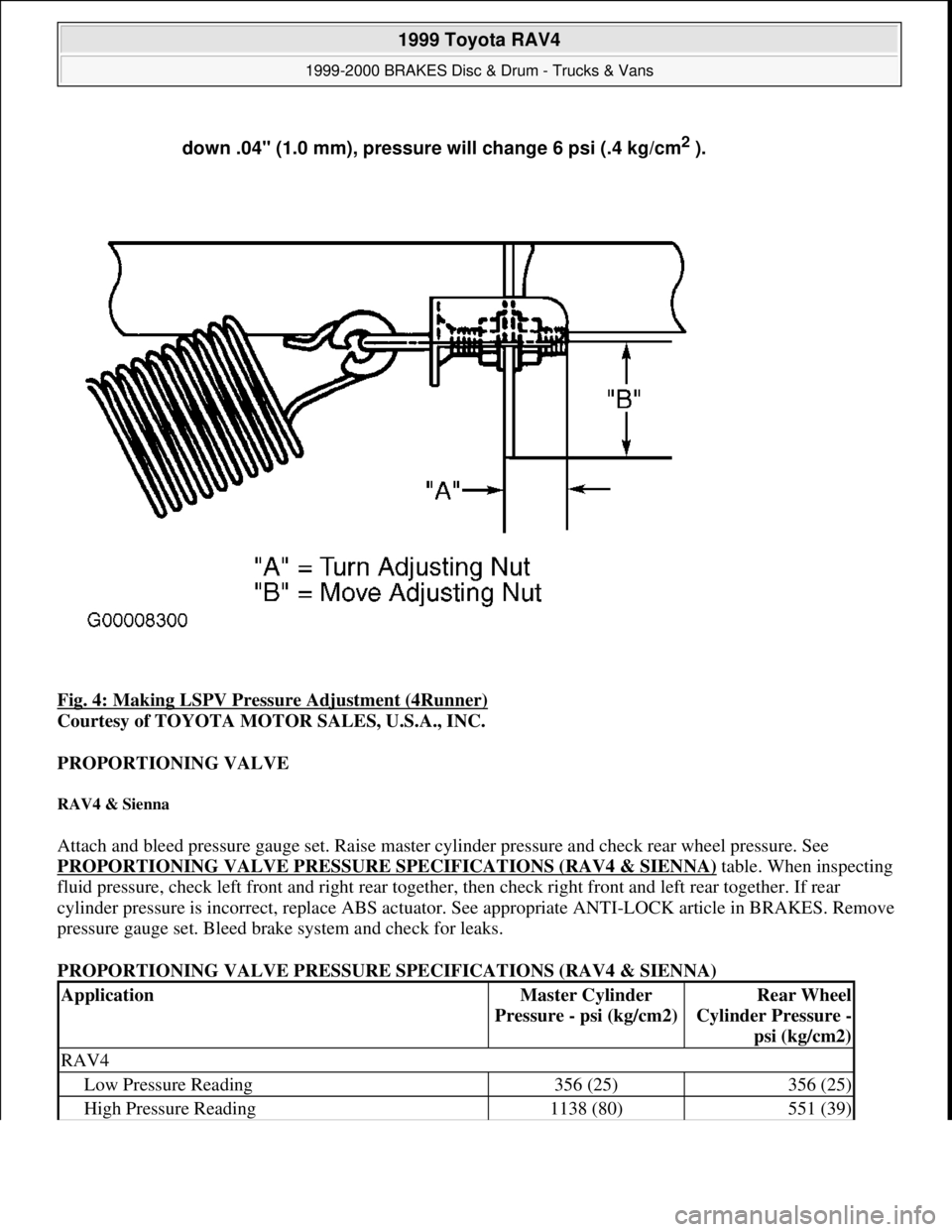
Fig. 4: Making LSPV Pressure Adjustment (4Runner)
Courtesy of TOYOTA MOTOR SALES, U.S.A., INC.
PROPORTIONING VALVE
RAV4 & Sienna
Attach and bleed pressure gauge set. Raise master cylinder pressure and check rear wheel pressure. See
PROPORTIONING VALVE PRESSURE SPECIFICATIONS (RAV4 & SIENNA)
table. When inspecting
fluid pressure, check left front and right rear together, then check right front and left rear together. If rear
cylinder pressure is incorrect, replace ABS actuator. See appropriate ANTI-LOCK article in BRAKES. Remove
pressure gauge set. Bleed brake system and check for leaks.
PROPORTIONING VALVE PRESSURE SPECIFICATIONS (RAV4 & SIENNA) down .04" (1.0 mm), pressure will change 6 psi (.4 kg/cm
2 ).
ApplicationMaster Cylinder
Pressure - psi (kg/cm2)Rear Wheel
Cylinder Pressure -
psi (kg/cm2)
RAV4
Low Pressure Reading356 (25)356 (25)
High Pressure Reading1138 (80)551 (39)
1999 Toyota RAV4
1999-2000 BRAKES Disc & Drum - Trucks & Vans
Microsoft
Sunday, November 22, 2009 10:07:28 AMPage 9 © 2005 Mitchell Repair Information Company, LLC.
Page 353 of 1632
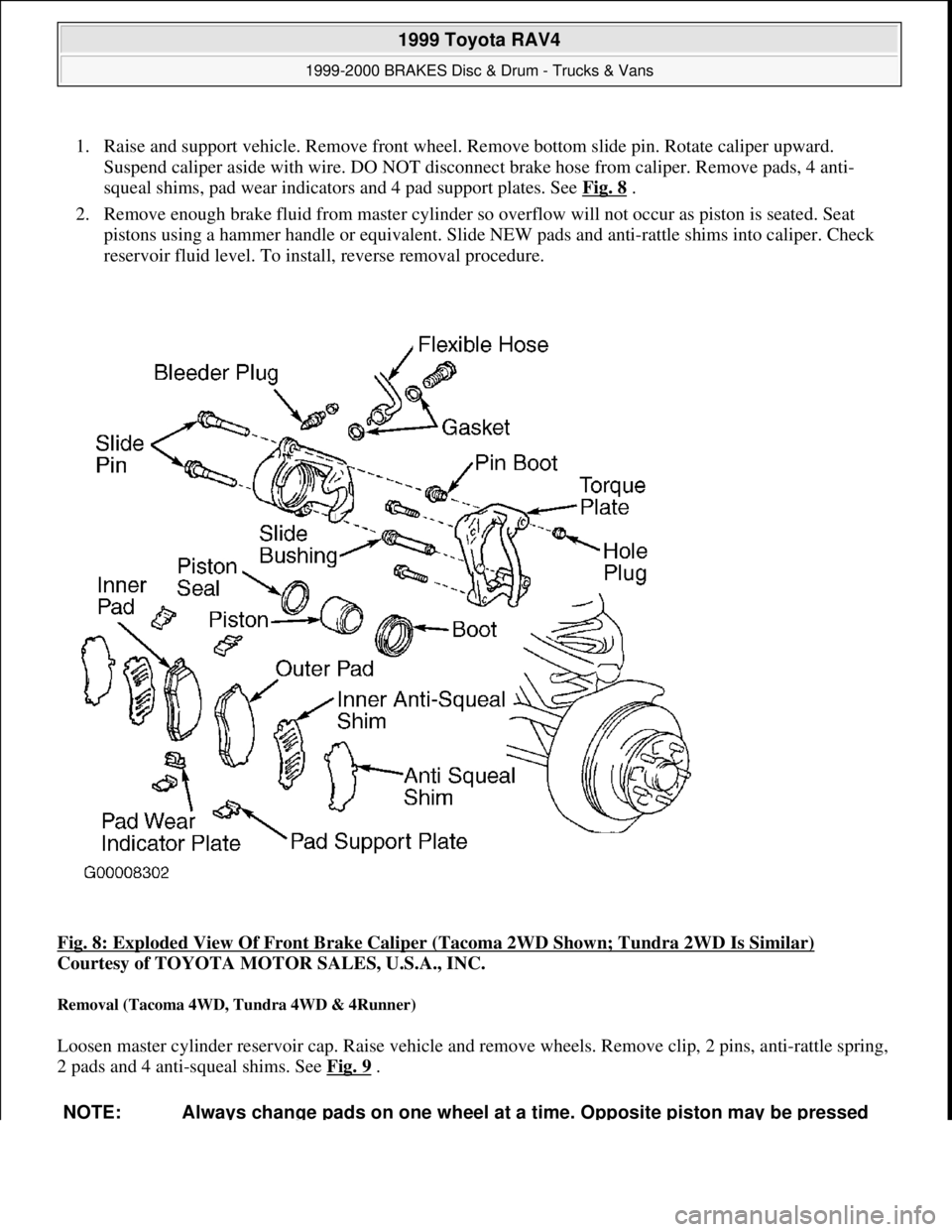
1. Raise and support vehicle. Remove front wheel. Remove bottom slide pin. Rotate caliper upward.
Suspend caliper aside with wire. DO NOT disconnect brake hose from caliper. Remove pads, 4 anti-
squeal shims, pad wear indicators and 4 pad support plates. See Fig. 8
.
2. Remove enough brake fluid from master cylinder so overflow will not occur as piston is seated. Seat
pistons using a hammer handle or equivalent. Slide NEW pads and anti-rattle shims into caliper. Check
reservoir fluid level. To install, reverse removal procedure.
Fig. 8: Exploded View Of Front Brake Caliper (Tacoma 2WD Shown; Tundra 2WD Is Similar)
Courtesy of TOYOTA MOTOR SALES, U.S.A., INC.
Removal (Tacoma 4WD, Tundra 4WD & 4Runner)
Loosen master cylinder reservoir cap. Raise vehicle and remove wheels. Remove clip, 2 pins, anti-rattle spring,
2 pads and 4 anti-squeal shims. See Fig. 9
.
NOTE: Always change pads on one wheel at a time. Opposite piston may be pressed
1999 Toyota RAV4
1999-2000 BRAKES Disc & Drum - Trucks & Vans
Microsoft
Sunday, November 22, 2009 10:07:28 AMPage 14 © 2005 Mitchell Repair Information Company, LLC.
Page 945 of 1632
Normal Service
Driven More Than 10 Miles Daily
No Operating Conditions From Severe Service Schedule
Severe Service (Unique Driving Conditions)
CAMSHAFT TIMING BELT
Inspect timing belt at 60,000 miles or 48 months and thereafter inspect timing belt every 15,000 miles, or 12
months. Replace belt as necessary.
The condition of camshaft drive belts should always be checked on vehicles which have more than 50,000
miles. Although some manufacturers do not recommend belt replacement at a specified mileage, others require
it at 60,000-100,000 miles. A camshaft drive belt failure may cause extensive damage to internal engine
components on most engines, although some designs do not allow piston-to-valve contact. These designs are
often called Free Wheeling.
Many manufacturers changed their maintenance and warranty schedules in the mid-1980's to reflect timing belt
inspection and/or replacement at 50,000-60,000 miles. Most service interval schedules in this manual reflect
these changes.
Belts or components should be inspected and replaced if any of the following conditions exist:
Cracks Or Tears In Belt Surface
Missing, Damaged, Cracked Or Rounded Teeth
Oil Contamination
Damaged Or Faulty Tensioners
Incorrect Tension Adjustment NOTE: Use the Severe Service schedule if the vehicle to be serviced is operated under
ANY (one or more) of these conditions:
Towing a trailer or using a camper or car-top carrier.
Repeated short trips of less than 5 miles in temperatures below freezing.
Extensive idling or low-speed driving for long distances as in heavy
commercial use such as delivery, taxi or patrol car.
Operating on rough, muddy or salt covered roads.
Operating on unpaved or dusty roads.
CAUTION: Failure to replace a faulty camshaft timing belt may result in serious
engine damage.
1999 Toyota RAV4
MAINTENANCE INFORMATION 1997-99 MAINTENANCE Toyota Maintenance Information
Microsoft
Sunday, November 22, 2009 10:32:41 AMPage 3 © 2005 Mitchell Repair Information Company, LLC.
Page 949 of 1632
If battery is replaced, it should be of the same group number as shown on original battery label.
CAUTIONS & WARNINGS
SUPPLEMENTAL RESTRAINT SYSTEM (AIR BAG)
Modifications or improper maintenance, including incorrect removal and installation of the Supplemental
Restraint System (SRS), can adversely affect system performance. DO NOT cover, obstruct or change the
steering wheel horn pad in any way, as such action could cause improper function of the system. Use only plain
water when cleaning the horn pad. Solvents or cleaners could adversely affect the air bag cover and cause
improper deployment of the system.
AIR CONDITIONING SERVICING
ANTI-LOCK BRAKE SYSTEM CAUTION: When battery is disconnected, vehicles equipped with computers may lose
memory data. When battery power is restored, driveability problems may
exist on some vehicles. These vehicles may require a relearn procedure.
See COMPUTER RELEARN PROCEDURES article in the GENERAL
INFORMATION section.
WARNING:To avoid injury from accidental air bag deployment, read and carefully
follow all warnings and service precautions. See appropriate AIR BAG
RESTRAINT SYSTEM article in ACCESSORIES/SAFETY EQUIPMENT.
CAUTION: Disconnect negative battery cable before servicing any air bag system,
steering column or passenger side dash component. After any repair, turn
ignition key to the ON position from passenger's side of vehicle in case of
accidental air bag inflation
NOTE: See the AIR BAG RESTRAINT SYSTEM article in the ACCESSORIES/SAFETY
EQUIPMENT Section.
CAUTION: Avoid breathing R-134a refrigerant and PAG lubricant vapors, exposure
may irritate eyes, nose and throat. To remove R-134a from system use R-
134a recycling equipment that meets SAE J2210 specifications. If
accidental system discharge occurs, ventilate work area before resuming
service.
WARNING:R-134a service equipment or vehicle A/C systems SHOULD NOT be
pressure tested or leak tested with compressed air. Some mixtures of
air/R134a have shown to be combustible at elevated pressures. These
mixtures are dangerous and may cause fire and/or explosions. See AIR
CONDITIONING SERVICE article in GENERAL INFORMATION section.
1999 Toyota RAV4
MAINTENANCE INFORMATION 1997-99 MAINTENANCE Toyota Maintenance Information
Microsoft
Sunday, November 22, 2009 10:32:42 AMPage 7 © 2005 Mitchell Repair Information Company, LLC.