bolt pattern TOYOTA RAV4 1996 Service Repair Manual
[x] Cancel search | Manufacturer: TOYOTA, Model Year: 1996, Model line: RAV4, Model: TOYOTA RAV4 1996Pages: 1632, PDF Size: 41.64 MB
Page 26 of 1632
1. Check charging system voltage. Ensure 10-14 volts is present. If charging system voltage is okay, go to
next step. If charging system voltage is not okay, check and repair charging system.
2. Turn ignition switch to ON position. Ensure ABS warning light comes on, then goes out after 3 seconds.
If ABS warning light does not illuminate, check fuse, bulb, and wiring harness. See ABS WARNING
LIGHT under DIAGNOSIS & TESTING. Turn ignition off.
3. Using a jumper wire, jumper terminals Ts and E
1 of DLC1. DLC1 is located in engine compartment on
left side of engine. See Fig. 2
. Ensure ABS warning light blinks 4 times per second. If ABS light does
not blink, go to ABS WARNING LIGHT
under DIAGNOSIS & TESTING. If ABS warning light
blinks, go to next step.
4. Using a floor jack, slowly jack up rear of vehicle. On vehicles with 215/70R16 tires, raise vehicle to a
height of 25.59-27.95" (650-710 mm). On vehicles with 235/60R16 tires, raise vehicle to a height of
26.38-28.74" (670-730 mm). If ABS warning light illuminates at specified height, check deceleration
sensor installation. If installation is okay, replace deceleration sensor. Lower vehicle.
5. Using a floor jack, slowly jack up front of vehicle. On vehicles with 215/70R16 tires, raise vehicle to a
height of 21.20-23.56" (550-610 mm). On vehicles with 235/60R16 tires, raise vehicle to a height of
22.44-24.80" (570-630 mm). If ABS warning light illuminates at specified height, check deceleration
sensor installation. If installation is okay, replace deceleration sensor. Lower vehicle.
6. Drive vehicle straight ahead at speed of 13 MPH or more. Lightly depress brake pedal. Ensure ABS
warning light pattern is normal (light blinks 4 times per second).
7. While driving vehicle straight ahead at speed of 13 MPH or more, moderately depress brake pedal.
Ensure ABS warning light illuminates in a solid pattern (light does not blink) while braking.
8. While driving vehicle straight ahead at speed of 13 MPH or more, firmly depress brake pedal. Ensure
ABS warning light illumination pattern changes from a solid pattern (light does not blink) to a normal
pattern (light blinks 4 times per second), then back to a solid pattern while braking.
9. If ABS warning light does not illuminate as described in steps 6 -8 , check deceleration sensor
installation. If installation is okay, replace deceleration sensor. Stop vehicle and turn ignition off. Remove
jumper wire from DLC1.
REMOVAL & INSTALLATION
ACTUATOR
Removal & Installation
Turn ignition off. Disconnect brakelines attached to actuator. Remove power steering hose retaining bracket
bolt and power steering reservoir. Disconnect actuator electrical connectors. Remove bolts, nuts and washers.
Remove actuator assembly. Remove actuator from actuator bracket. Remove cushions and holders from NOTE: When measuring vehicle height in following steps, measure at center of
lower body of vehicle.
WARNING:Hydraulic system may be under high pressure. Use caution when opening
hydraulic system.
1999 Toyota RAV4
1999-2000 BRAKES Anti-Lock - RAV4
Microsoft
Sunday, November 22, 2009 10:06:17 AMPage 26 © 2005 Mitchell Repair Information Company, LLC.
Page 177 of 1632
washer. Remove nut and washer. Remove Park/Neutral Position (PNP) switch.
3. Remove throttle cable retaining bolt. Remove solenoid harness connector retaining bolt (if applicable).
Remove vehicle speed sensor mounted in differential cover. Remove sensor adapter. Remove direct
clutch speed (T/M revolution) sensor mounted to upper case cover (if equipped). Remove upper case
cover. Remove transaxle oil pan. Examine any contamination in pan to aid in diagnosis.
4. Remove oil stainer (filter) and oil pipe hold-down bracket. Remove manual valve body including detent
spring. Gently remove all oil pipes by prying up on end of pipe with screwdriver.
5. Disconnect solenoid harness connectors. Remove connector clamp and apply pipe retainer. Remove 1st
and reverse apply pipe. Remove valve body bolts. Remove wiring harness clamp. Disconnect throttle
cable from cam and remove valve body.
6. Remove throttle cable and solenoid wiring harness. Remove 2nd brake apply gasket. Loosen accumulator
cover bolts in crisscross pattern. Remove cover and gasket. Remove forward clutch accumulator. See Fi
g.
10 .
7. Remove remaining accumulators by applying 14 psi (1kg/cm
2 ) of air pressure to apply hole. See Fig.
11 . Cover accumulator bores with a rag when applying air.
8. Mark 2nd coast brake servo apply piston rod where it meets case. Apply 57-114 psi (4-8 kg/cm
2 ) of air
pressure to apply hole and measure piston rod travel (stroke). See Fig. 12
. Piston rod travel should
be .079-.138" (2.0-3.5 mm). If rod travel is not within specification, further inspect band during
disassembly.
9. Remove 2nd coast brake piston cover snap ring. Apply air to oil hole and remove cover and piston
assembly. See Fig. 12
. Remove oil pump bolts. Using appropriate puller, remove oil pump.
10. Remove direct clutch and forward clutch. Separate components and remove thrust washer. Remove thrust
bearings from front and rear of forward clutch. Push out 2nd coast brake band anchor pin. Remove band
and inspect.
11. Remove front planetary ring gear. Remove front planetary gear with thrust bearings on either side.
Remove thrust bearings. Remove sun gear shell with thrust washer.
12. Apply compressed air to 2nd brake piston port and check operation of 2nd brake. See Fig. 13
. Remove
2nd coast brake band guide. DO NOT separate band guide and bolt. Remove snap ring securing 2nd
brake drum. Remove drum.
13. Remove 2nd brake piston return spring. Remove No. 1 one-way clutch. Remove 2nd brake clutch discs,
plates and flange. Note number and location of components. Remove snap ring securing No. 2 one-way
clutch and rear planetary gear. See Fig. 14
. Remove components.
14. Remove thrust washer from rear planetary gear. Remove rear planetary ring gear with thrust bearing.
Apply air into appropriate passage to check 1st and reverse brake operation. See Fig. 15
.
15. Using feeler gauge, check pack clearance of 1st and reverse brake assembly. Clearance should be .033-
.081" (.85-2.05 mm) for A-540E transaxle, .041-.085" (1.04-2.16 mm) for A-540H transaxle, or .076-
.106" (1.92-2.68 mm) for A-541E transaxle. Remove snap ring securing 1st and reverse brake. Remove
1st and reverse brake discs, plates and flange. Note number and location of components.
16. From back of transaxle, remove 13 bolts securing overdrive unit. Using soft-faced hammer, tap around
outside of case until overdrive unit loosens and can be removed.
17. Remove overdrive (OD) planetary gear from transaxle case. Remove OD brake drum. See Fig. 14
.
Remove gaskets for OD clutch apply and OD brake apply ports.
18. Usin
g appropriate compressor, compress 1st and reverse piston. See Fig. 16 . Remove snap ring. Apply
1998 Toyota Avalon XLS
1997-99 AUTOMATIC TRANSMISSIONS Toyota A-540E, A-540H & A-541E Overhaul
Helpmelearn
November-03-08 10:28:17 AMPage 23 © 2005 Mitchell Repair Information Company, LLC.
Page 183 of 1632
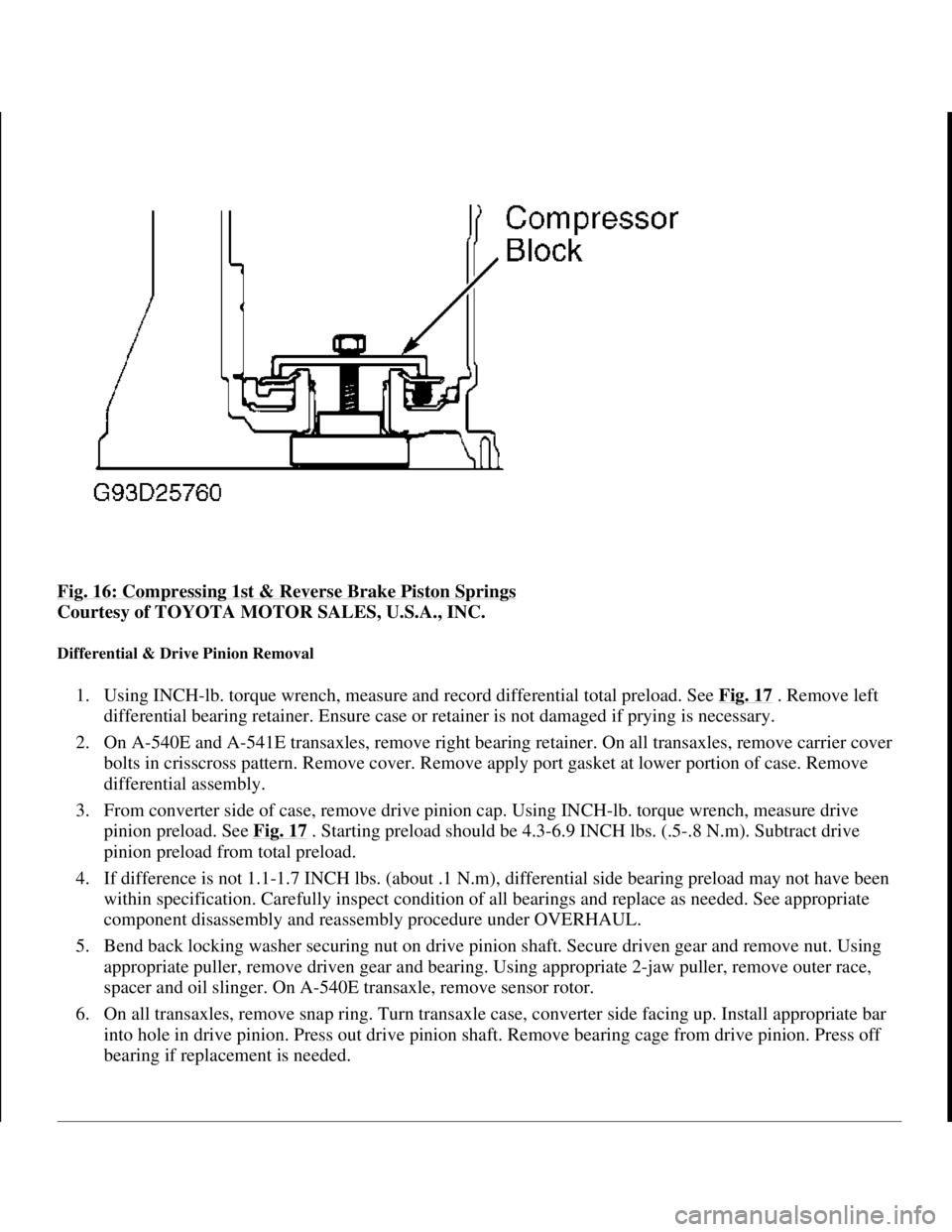
Fig. 16: Compressing 1st & Reverse Brake Piston Springs
Courtesy of TOYOTA MOTOR SALES, U.S.A., INC.
Differential & Drive Pinion Removal
1. Using INCH-lb. torque wrench, measure and record differential total preload. See Fig. 17 . Remove left
differential bearing retainer. Ensure case or retainer is not damaged if prying is necessary.
2. On A-540E and A-541E transaxles, remove right bearing retainer. On all transaxles, remove carrier cover
bolts in crisscross pattern. Remove cover. Remove apply port gasket at lower portion of case. Remove
differential assembly.
3. From converter side of case, remove drive pinion cap. Using INCH-lb. torque wrench, measure drive
pinion preload. See Fig. 17
. Starting preload should be 4.3-6.9 INCH lbs. (.5-.8 N.m). Subtract drive
pinion preload from total preload.
4. If difference is not 1.1-1.7 INCH lbs. (about .1 N.m), differential side bearing preload may not have been
within specification. Carefully inspect condition of all bearings and replace as needed. See appropriate
component disassembly and reassembly procedure under OVERHAUL.
5. Bend back locking washer securing nut on drive pinion shaft. Secure driven gear and remove nut. Using
appropriate puller, remove driven gear and bearing. Using appropriate 2-jaw puller, remove outer race,
spacer and oil slinger. On A-540E transaxle, remove sensor rotor.
6. On all transaxles, remove snap ring. Turn transaxle case, converter side facing up. Install appropriate bar
into hole in drive pinion. Press out drive pinion shaft. Remove bearing cage from drive pinion. Press off
bearing if replacement is needed.
1998 Toyota Avalon XLS
1997-99 AUTOMATIC TRANSMISSIONS Toyota A-540E, A-540H & A-541E Overhaul
Helpmelearn
November-03-08 10:28:17 AMPage 29 © 2005 Mitchell Repair Information Company, LLC.
Page 249 of 1632
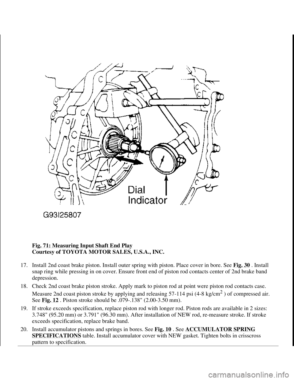
Fig. 71: Measuring Input Shaft End Play
Courtesy of TOYOTA MOTOR SALES, U.S.A., INC.
17. Install 2nd coast brake piston. Install outer spring with piston. Place cover in bore. See Fig. 30
. Install
snap ring while pressing in on cover. Ensure front end of piston rod contacts center of 2nd brake band
depression.
18. Check 2nd coast brake piston stroke. Apply mark to piston rod at point were piston rod contacts case.
Measure 2nd coast piston stroke by applying and releasing 57-114 psi (4-8 kg/cm
2 ) of compressed air.
See Fig. 12
. Piston stroke should be .079-.138" (2.00-3.50 mm).
19. If stroke exceeds specification, replace piston rod with longer rod. Piston rods are available in 2 sizes:
3.748" (95.20 mm) or 3.791" (96.30 mm). After installation of NEW rod, re-measure stroke. If stroke
exceeds specification, replace brake band.
20. Install accumulator pistons and springs in bores. See Fig. 10
. See ACCUMULATOR SPRING
SPECIFICATIONS table. Install accumulator cover with NEW gasket. Tighten bolts in crisscross
pattern to specification.
1998 Toyota Avalon XLS
1997-99 AUTOMATIC TRANSMISSIONS Toyota A-540E, A-540H & A-541E Overhaul
Helpmelearn
November-03-08 10:28:20 AMPage 95 © 2005 Mitchell Repair Information Company, LLC.
Page 250 of 1632
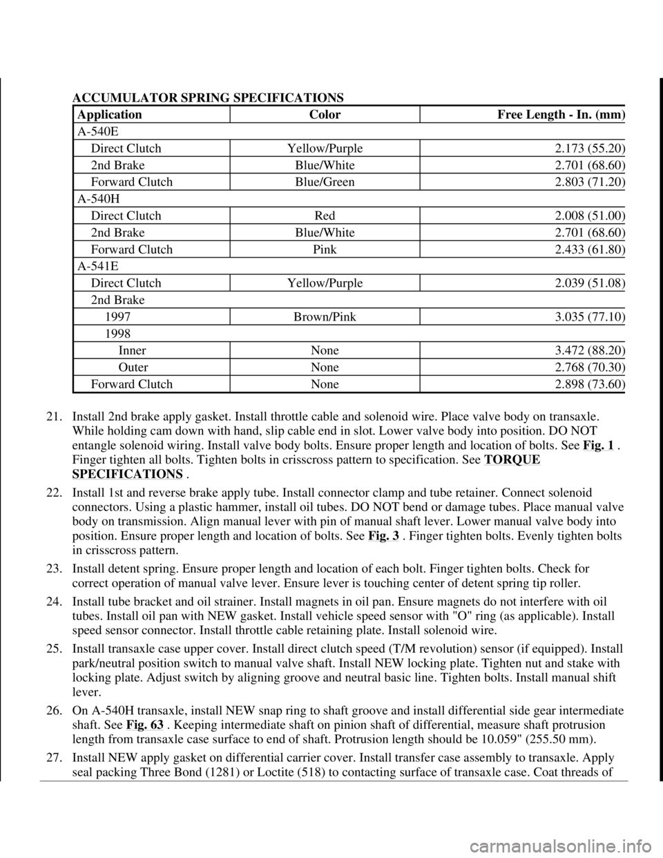
ACCUMULATOR SPRING SPECIFICATIONS
21. Install 2nd brake apply gasket. Install throttle cable and solenoid wire. Place valve body on transaxle.
While holding cam down with hand, slip cable end in slot. Lower valve body into position. DO NOT
entangle solenoid wiring. Install valve body bolts. Ensure proper length and location of bolts. See Fig. 1
.
Finger tighten all bolts. Tighten bolts in crisscross pattern to specification. See TORQUE
SPECIFICATIONS .
22. Install 1st and reverse brake apply tube. Install connector clamp and tube retainer. Connect solenoid
connectors. Using a plastic hammer, install oil tubes. DO NOT bend or damage tubes. Place manual valve
body on transmission. Align manual lever with pin of manual shaft lever. Lower manual valve body into
position. Ensure proper length and location of bolts. See Fig. 3
. Finger tighten bolts. Evenly tighten bolts
in crisscross pattern.
23. Install detent spring. Ensure proper length and location of each bolt. Finger tighten bolts. Check for
correct operation of manual valve lever. Ensure lever is touching center of detent spring tip roller.
24. Install tube bracket and oil strainer. Install magnets in oil pan. Ensure magnets do not interfere with oil
tubes. Install oil pan with NEW gasket. Install vehicle speed sensor with "O" ring (as applicable). Install
speed sensor connector. Install throttle cable retaining plate. Install solenoid wire.
25. Install transaxle case upper cover. Install direct clutch speed (T/M revolution) sensor (if equipped). Install
park/neutral position switch to manual valve shaft. Install NEW locking plate. Tighten nut and stake with
locking plate. Adjust switch by aligning groove and neutral basic line. Tighten bolts. Install manual shift
lever.
26. On A-540H transaxle, install NEW snap ring to shaft groove and install differential side gear intermediate
shaft. See Fig. 63
. Keeping intermediate shaft on pinion shaft of differential, measure shaft protrusion
length from transaxle case surface to end of shaft. Protrusion length should be 10.059" (255.50 mm).
27. Install NEW apply gasket on differential carrier cover. Install transfer case assembly to transaxle. Apply
seal packing Three Bond (1281) or Loctite (518) to contacting surface of transaxle case. Coat threads of
ApplicationColorFree Length - In. (mm)
A-540E
Direct ClutchYellow/Purple2.173 (55.20)
2nd BrakeBlue/White2.701 (68.60)
Forward ClutchBlue/Green2.803 (71.20)
A-540H
Direct ClutchRed2.008 (51.00)
2nd BrakeBlue/White2.701 (68.60)
Forward ClutchPink2.433 (61.80)
A-541E
Direct ClutchYellow/Purple2.039 (51.08)
2nd Brake
1997Brown/Pink3.035 (77.10)
1998
InnerNone3.472 (88.20)
OuterNone2.768 (70.30)
Forward ClutchNone2.898 (73.60)
1998 Toyota Avalon XLS
1997-99 AUTOMATIC TRANSMISSIONS Toyota A-540E, A-540H & A-541E Overhaul
Helpmelearn
November-03-08 10:28:20 AMPage 96 © 2005 Mitchell Repair Information Company, LLC.
Page 455 of 1632
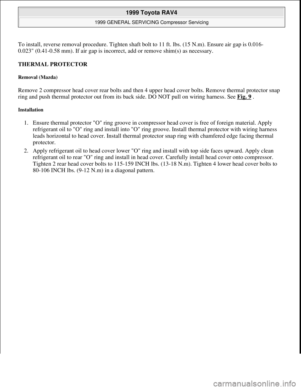
To install, reverse removal procedure. Tighten shaft bolt to 11 ft. lbs. (15 N.m). Ensure air gap is 0.016-
0.023" (0.41-0.58 mm). If air gap is incorrect, add or remove shim(s) as necessary.
THERMAL PROTECTOR
Removal (Mazda)
Remove 2 compressor head cover rear bolts and then 4 upper head cover bolts. Remove thermal protector snap
ring and push thermal protector out from its back side. DO NOT pull on wiring harness. See Fig. 9
.
Installation
1. Ensure thermal protector "O" ring groove in compressor head cover is free of foreign material. Apply
refrigerant oil to "O" ring and install into "O" ring groove. Install thermal protector with wiring harness
leads horizontal to head cover. Install thermal protector snap ring with chamfered edge facing thermal
protector.
2. Apply refrigerant oil to head cover lower "O" ring and install with top side faces upward. Apply clean
refrigerant oil to rear "O" ring and install in head cover. Carefully install head cover onto compressor.
Tighten 2 rear head cover bolts to 115-159 INCH lbs. (13-18 N.m). Tighten 4 lower head cover bolts to
80-106 INCH lbs. (9-12 N.m) in a dia
gonal pattern.
1999 Toyota RAV4
1999 GENERAL SERVICING Compressor Servicing
Microsoft
Sunday, November 22, 2009 10:31:50 AMPage 18 © 2005 Mitchell Repair Information Company, LLC.
Page 466 of 1632
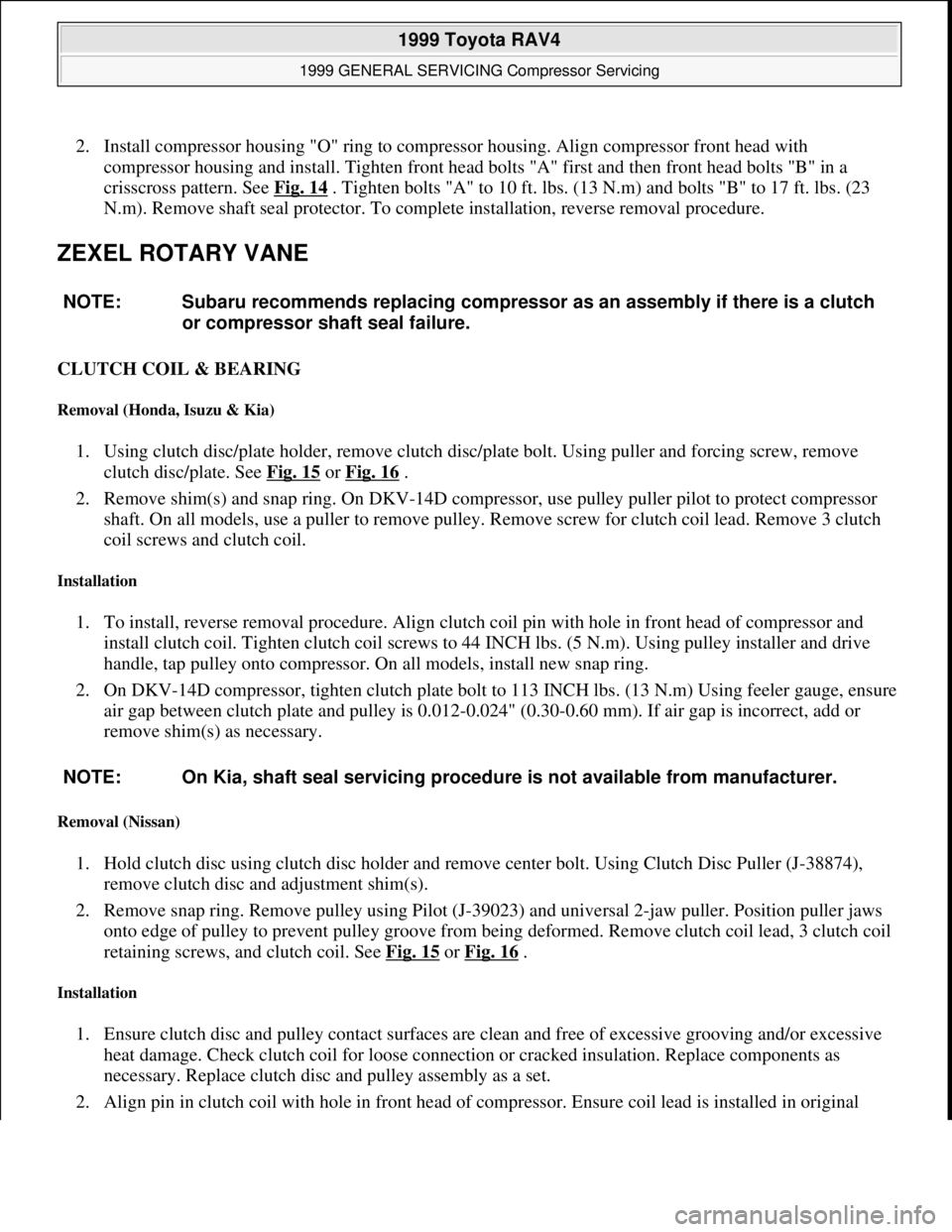
2. Install compressor housing "O" ring to compressor housing. Align compressor front head with
compressor housing and install. Tighten front head bolts "A" first and then front head bolts "B" in a
crisscross pattern. See Fig. 14
. Tighten bolts "A" to 10 ft. lbs. (13 N.m) and bolts "B" to 17 ft. lbs. (23
N.m). Remove shaft seal protector. To complete installation, reverse removal procedure.
ZEXEL ROTARY VANE
CLUTCH COIL & BEARING
Removal (Honda, Isuzu & Kia)
1. Using clutch disc/plate holder, remove clutch disc/plate bolt. Using puller and forcing screw, remove
clutch disc/plate. See Fig. 15
or Fig. 16 .
2. Remove shim(s) and snap ring. On DKV-14D compressor, use pulley puller pilot to protect compressor
shaft. On all models, use a puller to remove pulley. Remove screw for clutch coil lead. Remove 3 clutch
coil screws and clutch coil.
Installation
1. To install, reverse removal procedure. Align clutch coil pin with hole in front head of compressor and
install clutch coil. Tighten clutch coil screws to 44 INCH lbs. (5 N.m). Using pulley installer and drive
handle, tap pulley onto compressor. On all models, install new snap ring.
2. On DKV-14D compressor, tighten clutch plate bolt to 113 INCH lbs. (13 N.m) Using feeler gauge, ensure
air gap between clutch plate and pulley is 0.012-0.024" (0.30-0.60 mm). If air gap is incorrect, add or
remove shim(s) as necessary.
Removal (Nissan)
1. Hold clutch disc using clutch disc holder and remove center bolt. Using Clutch Disc Puller (J-38874),
remove clutch disc and adjustment shim(s).
2. Remove snap ring. Remove pulley using Pilot (J-39023) and universal 2-jaw puller. Position puller jaws
onto edge of pulley to prevent pulley groove from being deformed. Remove clutch coil lead, 3 clutch coil
retaining screws, and clutch coil. See Fig. 15
or Fig. 16 .
Installation
1. Ensure clutch disc and pulley contact surfaces are clean and free of excessive grooving and/or excessive
heat damage. Check clutch coil for loose connection or cracked insulation. Replace components as
necessary. Replace clutch disc and pulley assembly as a set.
2. Align pin in clutch coil with hole in front head of compressor. Ensure coil lead is installed in original NOTE: Subaru recommends replacing compressor as an assembly if there is a clutch
or compressor shaft seal failure.
NOTE: On Kia, shaft seal servicing procedure is not available from manufacturer.
1999 Toyota RAV4
1999 GENERAL SERVICING Compressor Servicing
Microsoft
Sunday, November 22, 2009 10:31:50 AMPage 29 © 2005 Mitchell Repair Information Company, LLC.
Page 618 of 1632
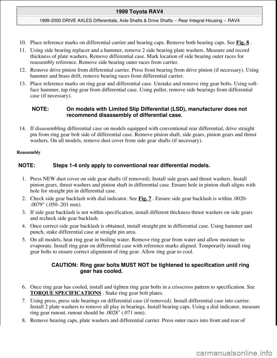
10. Place reference marks on differential carrier and bearing caps. Remove both bearing caps. See Fig. 8 .
11. Using side bearing replacer and a hammer, remove 2 side bearing plate washers. Measure and record
thickness of plate washers. Remove differential case. Mark location of side bearing outer races for
reassembly reference. Remove side bearing outer races from carrier.
12. Remove drive pinion from differential carrier. Press front bearing from drive pinion (if necessary). Using
hammer and brass drift, remove bearing races from differential carrier.
13. Place reference marks on ring gear and differential case. Unstake and remove ring gear bolts. Using soft-
face hammer, tap ring gear from differential case. Using puller, remove side bearings from differential
case (if necessary).
14. If disassembling differential case on models equipped with conventional rear differential, drive straight
pin from ring gear bolt side of differential case. Remove pinion shaft, side gears, pinion gears and thrust
washers. On all models, remove dust cover from side gear shafts (if necessary).
Reassembly
1. Press NEW dust cover on side gear shafts (if removed). Install side gears and thrust washers. Install
pinion gears, thrust washers and pinion shaft in differential case. Ensure hole in pinion shaft aligns with
hole for straight pin in differential case.
2. Check side gear backlash with dial indicator. See Fig. 7
. Ensure side gear backlash is within .0020-
.0079" (.050-.201 mm).
3. If side gear backlash is not within specification, install different thickness thrust washers on side gears
and recheck side gear backlash.
4. Once correct side gear backlash is obtained, install straight pin in differential case. Using hammer and
punch, stake differential case at straight pin area.
5. On all models, heat ring gear in boiling water. Remove ring gear from water and allow moisture to
evaporate. Install ring gear on differential case with reference marks aligned. Temporarily install ring
gear bolts to ensure correct alignment of ring gear. Allow ring gear to cool.
6. Once ring gear has cooled, install and tighten ring gear bolts in a crisscross pattern to specification. See
TORQUE SPECIFICATIONS
. Stake ring gear bolt plates.
7. Using press, press side bearings on differential case (if removed). Install differential case into carrier.
Install 2 plate washers to remove all play in bearings. Install bearing caps. Using a dial indicator, measure
ring gear runout. runout should be .0028" (.071 mm).
8. Remove bearing caps, plate washers and differential carrier. Press outer races into front and rear of NOTE: On models with Limited Slip Differential (LSD), manufacturer does not
recommend disassembly of differential case.
NOTE: Steps 1-4 only apply to conventional rear differential models.
CAUTION: Ring gear bolts MUST NOT be tightened to specification until ring
gear has cooled.
1999 Toyota RAV4
1999-2000 DRIVE AXLES Differentials, Axle Shafts & Drive Shafts -- Rear Integral Housing -- RAV4
Microsoft
Sunday, November 22, 2009 10:09:38 AMPage 13 © 2005 Mitchell Repair Information Company, LLC.
Page 619 of 1632
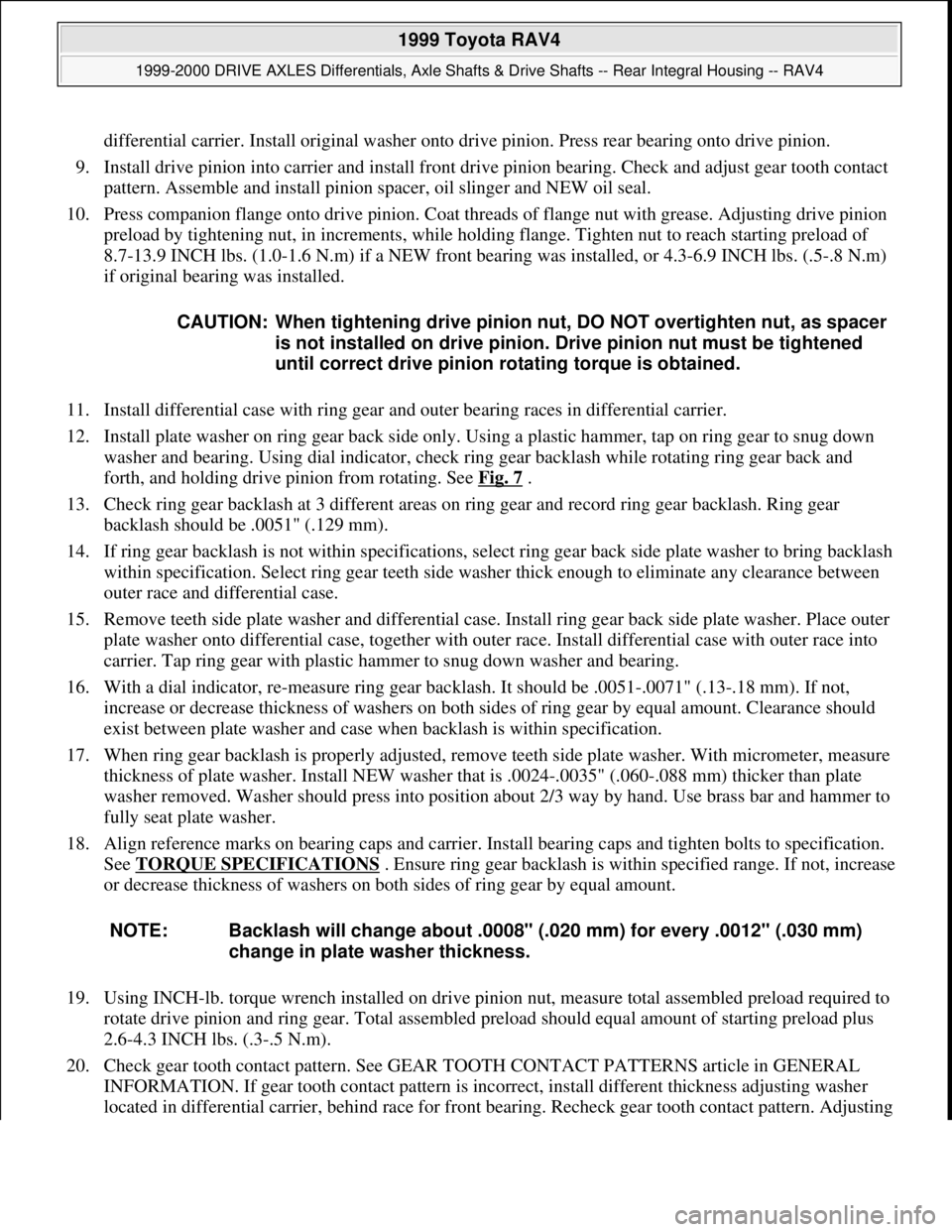
differential carrier. Install original washer onto drive pinion. Press rear bearing onto drive pinion.
9. Install drive pinion into carrier and install front drive pinion bearing. Check and adjust gear tooth contact
pattern. Assemble and install pinion spacer, oil slinger and NEW oil seal.
10. Press companion flange onto drive pinion. Coat threads of flange nut with grease. Adjusting drive pinion
preload by tightening nut, in increments, while holding flange. Tighten nut to reach starting preload of
8.7-13.9 INCH lbs. (1.0-1.6 N.m) if a NEW front bearing was installed, or 4.3-6.9 INCH lbs. (.5-.8 N.m)
if original bearing was installed.
11. Install differential case with ring gear and outer bearing races in differential carrier.
12. Install plate washer on ring gear back side only. Using a plastic hammer, tap on ring gear to snug down
washer and bearing. Using dial indicator, check ring gear backlash while rotating ring gear back and
forth, and holding drive pinion from rotating. See Fig. 7
.
13. Check ring gear backlash at 3 different areas on ring gear and record ring gear backlash. Ring gear
backlash should be .0051" (.129 mm).
14. If ring gear backlash is not within specifications, select ring gear back side plate washer to bring backlash
within specification. Select ring gear teeth side washer thick enough to eliminate any clearance between
outer race and differential case.
15. Remove teeth side plate washer and differential case. Install ring gear back side plate washer. Place outer
plate washer onto differential case, together with outer race. Install differential case with outer race into
carrier. Tap ring gear with plastic hammer to snug down washer and bearing.
16. With a dial indicator, re-measure ring gear backlash. It should be .0051-.0071" (.13-.18 mm). If not,
increase or decrease thickness of washers on both sides of ring gear by equal amount. Clearance should
exist between plate washer and case when backlash is within specification.
17. When ring gear backlash is properly adjusted, remove teeth side plate washer. With micrometer, measure
thickness of plate washer. Install NEW washer that is .0024-.0035" (.060-.088 mm) thicker than plate
washer removed. Washer should press into position about 2/3 way by hand. Use brass bar and hammer to
fully seat plate washer.
18. Align reference marks on bearing caps and carrier. Install bearing caps and tighten bolts to specification.
See TORQUE SPECIFICATIONS
. Ensure ring gear backlash is within specified range. If not, increase
or decrease thickness of washers on both sides of ring gear by equal amount.
19. Using INCH-lb. torque wrench installed on drive pinion nut, measure total assembled preload required to
rotate drive pinion and ring gear. Total assembled preload should equal amount of starting preload plus
2.6-4.3 INCH lbs. (.3-.5 N.m).
20. Check gear tooth contact pattern. See GEAR TOOTH CONTACT PATTERNS article in GENERAL
INFORMATION. If gear tooth contact pattern is incorrect, install different thickness adjusting washer
located in differential carrier, behind race for front bearin
g. Recheck gear tooth contact pattern. Adjusting CAUTION: When tightening drive pinion nut, DO NOT overtighten nut, as spacer
is not installed on drive pinion. Drive pinion nut must be tightened
until correct drive pinion rotating torque is obtained.
NOTE: Backlash will change about .0008" (.020 mm) for every .0012" (.030 mm)
change in plate washer thickness.
1999 Toyota RAV4
1999-2000 DRIVE AXLES Differentials, Axle Shafts & Drive Shafts -- Rear Integral Housing -- RAV4
Microsoft
Sunday, November 22, 2009 10:09:38 AMPage 14 © 2005 Mitchell Repair Information Company, LLC.
Page 620 of 1632
washers are available in various thicknesses.
21. Remove companion flange and front bearing. Install NEW spacer on drive pinion. Install NEW front
bearing. Install oil slinger on drive pinion. Install drive pinion in differential carrier.
22. Apply grease to lip of NEW oil seal for drive pinion. Install oil seal in differential carrier until surface of
oil seal is .079" (2.01 mm) below surface of differential carrier.
23. Press companion flange onto drive pinion. Coat threads on drive pinion and NEW drive pinion nut with
gear oil. Install drive pinion nut. Hold companion flange and tighten nut to 80 ft. lbs. (108 N.m).
24. Measure preload of backlash between drive pinion and ring gear. Starting preload should be 8.7-13.9
INCH lbs. (1.0-1.6 N.m) with a NEW front bearing, or 4.3-6.9 INCH lbs. (.5-.8 N.m) with a reused
bearing.
25. If drive pinion starting preload exceeds specified range, replace bearing spacer and repeat procedure. If
starting preload is less than specified range, tighten drive pinion nut, in small increments, until specified
preload is reached. DO NOT exceed 174 ft. lbs. (236 N.m) torque on drive pinion nut. If torque is
exceeded, replace spacer and repeat procedure. DO NOT back off nut if torque is exceeded.
26. Once correct starting preload is obtained, recheck total preload, ring gear backlash, tooth contact pattern
between ring gear and drive pinion, and companion flange runout. When okay, stake drive pinion nut.
Install NEW side gear oil seals until flush with carrier end surface.
27. On models equipped with LSD, install NEW snap ring on end of side gear shafts. Coat snap rings with
grease. Using slide hammer, install side gear shafts until pinion shaft is contacted.
28. On models equipped with conventional rear differential, install side gear shafts. Install 2 NEW snap rings
into the inside of differential.
29. Clean carrier and cover contact surfaces. Apply sealant on differential carrier cover and install. Install and
tighten bolts to specification. See TORQUE SPECIFICATIONS
.
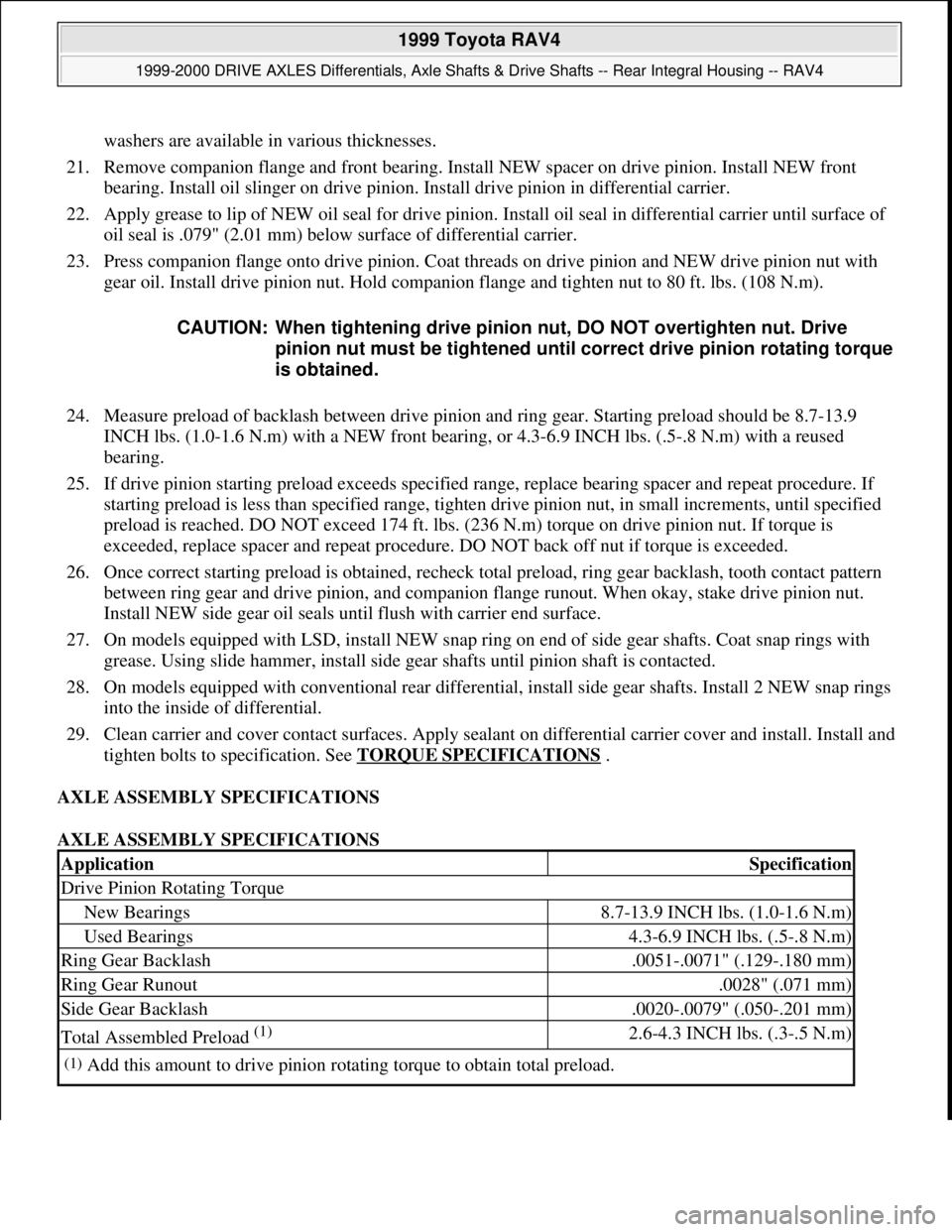
AXLE ASSEMBLY SPECIFICATIONS
AXLE ASSEMBLY SPECIFICATIONS CAUTION: When tightening drive pinion nut, DO NOT overtighten nut. Drive
pinion nut must be tightened until correct drive pinion rotating torque
is obtained.
ApplicationSpecification
Drive Pinion Rotating Torque
New Bearings8.7-13.9 INCH lbs. (1.0-1.6 N.m)
Used Bearings4.3-6.9 INCH lbs. (.5-.8 N.m)
Ring Gear Backlash.0051-.0071" (.129-.180 mm)
Ring Gear Runout.0028" (.071 mm)
Side Gear Backlash.0020-.0079" (.050-.201 mm)
Total Assembled Preload (1) 2.6-4.3 INCH lbs. (.3-.5 N.m)
(1)Add this amount to drive pinion rotating torque to obtain total preload.
1999 Toyota RAV4
1999-2000 DRIVE AXLES Differentials, Axle Shafts & Drive Shafts -- Rear Integral Housing -- RAV4
Microsoft
Sunday, November 22, 2009 10:09:38 AMPage 15 © 2005 Mitchell Repair Information Company, LLC.