radio TOYOTA RAV4 1996 Service Repair Manual
[x] Cancel search | Manufacturer: TOYOTA, Model Year: 1996, Model line: RAV4, Model: TOYOTA RAV4 1996Pages: 1632, PDF Size: 41.64 MB
Page 80 of 1632
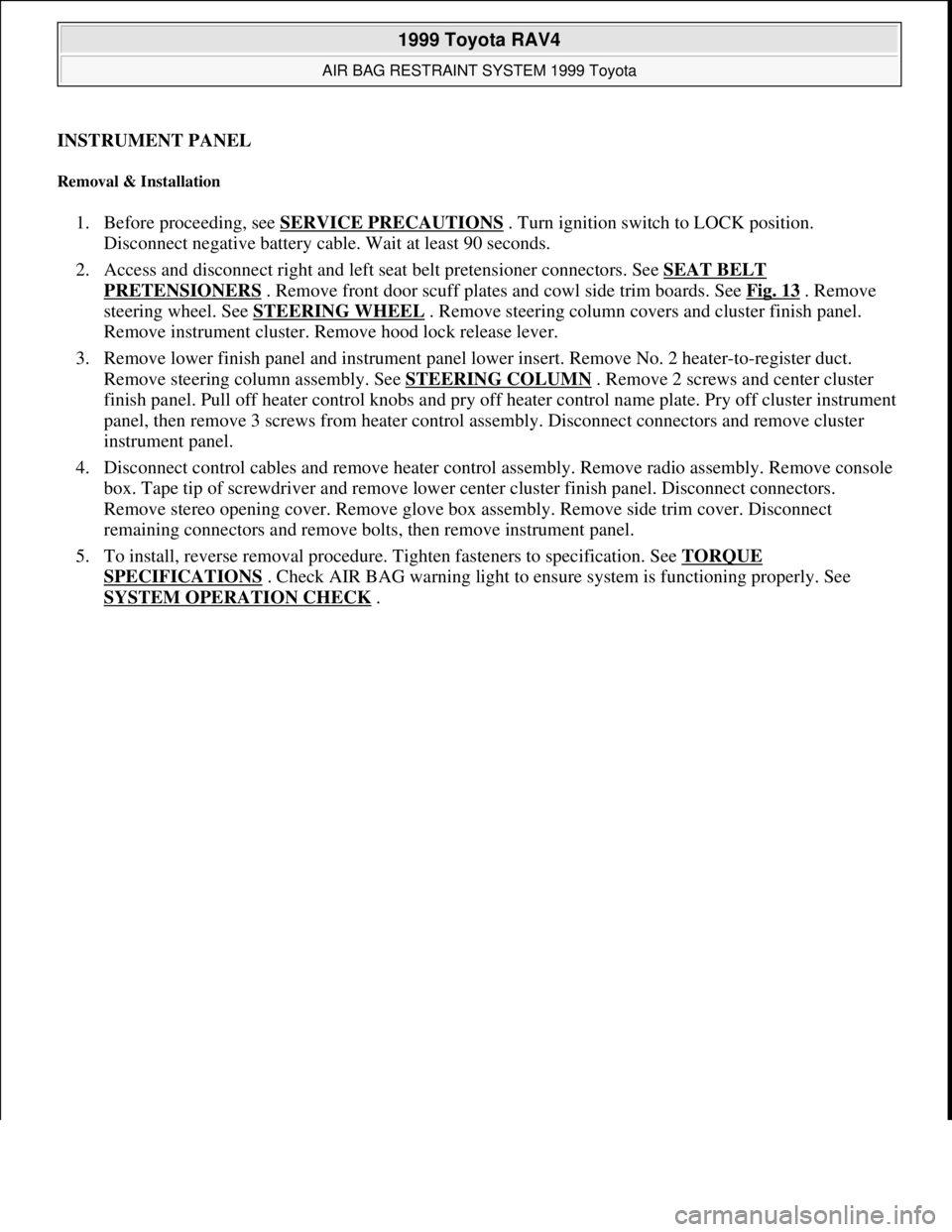
INSTRUMENT PANEL
Removal & Installation
1. Before proceeding, see SERVICE PRECAUTIONS . Turn ignition switch to LOCK position.
Disconnect negative battery cable. Wait at least 90 seconds.
2. Access and disconnect right and left seat belt pretensioner connectors. See SEAT BELT
PRETENSIONERS . Remove front door scuff plates and cowl side trim boards. See Fig. 13 . Remove
steering wheel. See STEERING WHEEL
. Remove steering column covers and cluster finish panel.
Remove instrument cluster. Remove hood lock release lever.
3. Remove lower finish panel and instrument panel lower insert. Remove No. 2 heater-to-register duct.
Remove steering column assembly. See STEERING COLUMN
. Remove 2 screws and center cluster
finish panel. Pull off heater control knobs and pry off heater control name plate. Pry off cluster instrument
panel, then remove 3 screws from heater control assembly. Disconnect connectors and remove cluster
instrument panel.
4. Disconnect control cables and remove heater control assembly. Remove radio assembly. Remove console
box. Tape tip of screwdriver and remove lower center cluster finish panel. Disconnect connectors.
Remove stereo opening cover. Remove glove box assembly. Remove side trim cover. Disconnect
remaining connectors and remove bolts, then remove instrument panel.
5. To install, reverse removal procedure. Tighten fasteners to specification. See TORQUE
SPECIFICATIONS . Check AIR BAG warning light to ensure system is functioning properly. See
SYSTEM OPERATION CHECK
.
1999 Toyota RAV4
AIR BAG RESTRAINT SYSTEM 1999 Toyota
Microsoft
Sunday, November 22, 2009 10:33:22 AMPage 17 © 2005 Mitchell Repair Information Company, LLC.
Page 143 of 1632
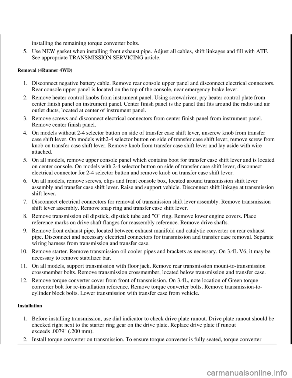
installing the remaining torque converter bolts.
5. Use NEW gasket when installing front exhaust pipe. Adjust all cables, shift linkages and fill with ATF.
See appropriate TRANSMISSION SERVICING article.
Removal (4Runner 4WD)
1. Disconnect negative battery cable. Remove rear console upper panel and disconnect electrical connectors.
Rear console upper panel is located on the top of the console, near emergency brake lever.
2. Remove heater control knobs from instrument panel. Using screwdriver, pry heater control plate from
center finish panel on instrument panel. Center finish panel is the panel that fits around the radio and air
outlet ducts, located at center of instrument panel.
3. Remove screws and disconnect electrical connectors from center finish panel from instrument panel.
Remove center finish panel.
4. On models without 2-4 selector button on side of transfer case shift lever, unscrew knob from transfer
case shift lever. On models with2-4 selector button on side of transfer case shift lever, remove screw from
knob on transfer case shift lever. Remove knob from transfer case shift lever and lay aside with wire
attached.
5. On all models, remove upper console panel which contains boot for transfer case shift lever and is located
on center console. On models with 2-4 selector button on side of transfer case shift lever, disconnect
electrical connector for 2-4 selector button and remove knob on transfer case shift lever.
6. On all models, remove screws, clips and front console box, located around transmission shift lever
assembly and transfer case shift lever. Raise and support vehicle. Disconnect shift linkage at transmission
shift lever.
7. Disconnect electrical connectors for removal of transmission shift lever assembly. Remove transmission
shift lever assembly. Remove snap ring and transfer case shift lever.
8. Remove transmission oil dipstick, dipstick tube and "O" ring. Remove lower engine covers. Place
reference marks on drive shaft flanges for reassembly reference. Remove drive shafts.
9. Remove front exhaust pipe, located between exhaust manifold and catalytic converter on rear exhaust
pipe. Disconnect and necessary electrical connectors for transmission and transfer case removal. Separate
wiring harness from transmission and transfer case.
10. Remove starter. Remove transmission oil cooler pipes and brackets as necessary. On 3.4L V6, it may be
necessary to remove stabilizer bar.
11. On all models, support transmission with floor jack. Remove rear transmission mount-to-transmission
crossmember bolts. Remove transmission crossmember, located below transmission and transfer case.
12. Remove torque converter cover from front of transmission. On 3.4L, note location of Green torque
converter bolt for re-installation reference. Remove torque converter bolts. Remove transmission-to-
cylinder block bolts. Lower transmission with transfer case from vehicle.
Installation
1. Before installing transmission, use dial indicator to check drive plate runout. Drive plate runout should be
checked right next to the starter ring gear on the drive plate. Replace drive plate if runout
exceeds .0079" (.200 mm).
2. Install torque converter on transmission. To ensure torque converter is fully seated, torque converter
1998 Toyota Avalon XLS
TRANSMISSION SERVICING - A/T 1997-98 TRANSMISSION SERVICING Toyota - Transmission Removal &
Installation
Helpmelearn
November-03-08 10:30:29 AMPage 31 © 2005 Mitchell Repair Information Company, LLC.
Page 851 of 1632
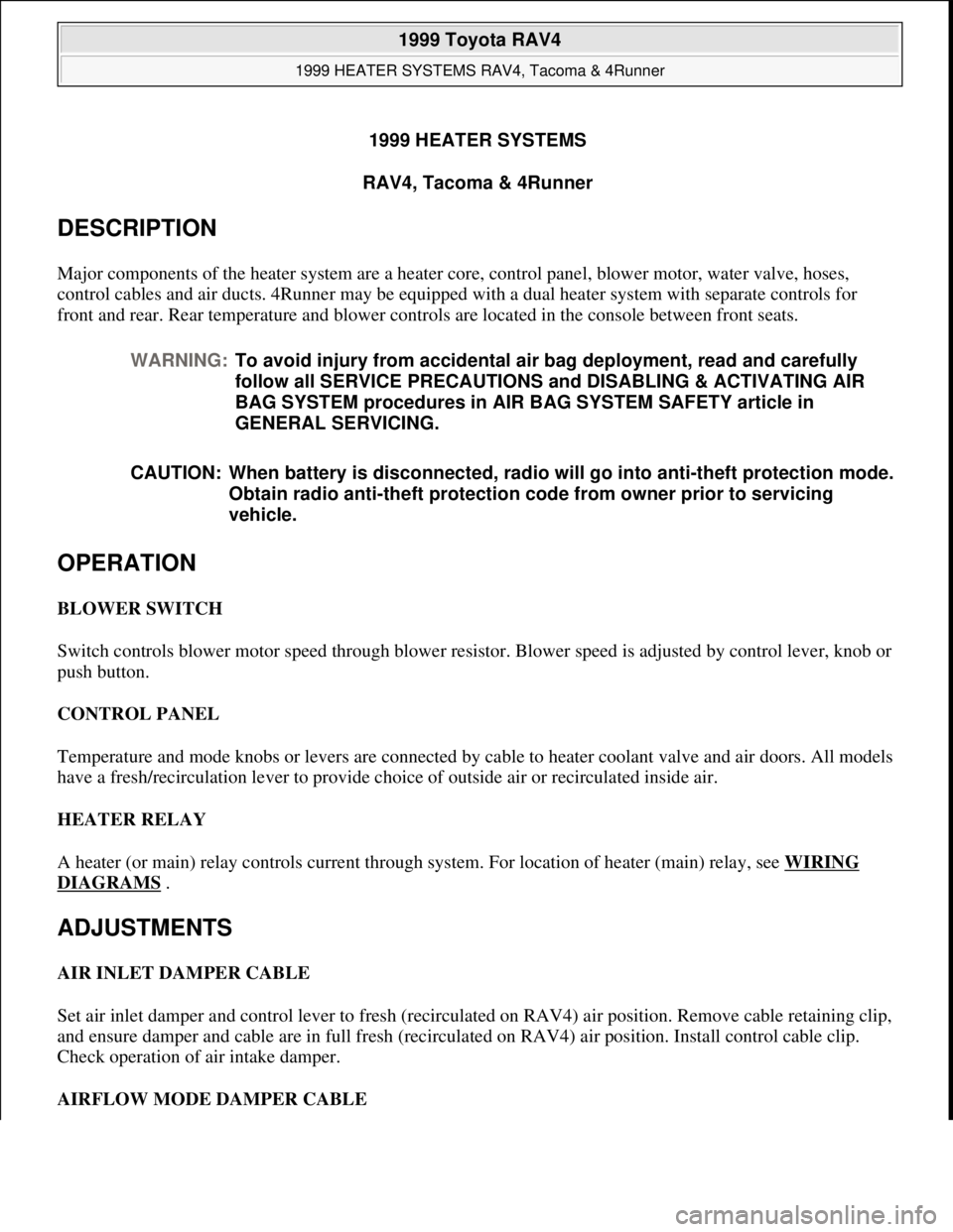
1999 HEATER SYSTEMS
RAV4, Tacoma & 4Runner
DESCRIPTION
Major components of the heater system are a heater core, control panel, blower motor, water valve, hoses,
control cables and air ducts. 4Runner may be equipped with a dual heater system with separate controls for
front and rear. Rear temperature and blower controls are located in the console between front seats.
OPERATION
BLOWER SWITCH
Switch controls blower motor speed through blower resistor. Blower speed is adjusted by control lever, knob or
push button.
CONTROL PANEL
Temperature and mode knobs or levers are connected by cable to heater coolant valve and air doors. All models
have a fresh/recirculation lever to provide choice of outside air or recirculated inside air.
HEATER RELAY
A heater (or main) relay controls current through system. For location of heater (main) relay, see WIRING
DIAGRAMS .
ADJUSTMENTS
AIR INLET DAMPER CABLE
Set air inlet damper and control lever to fresh (recirculated on RAV4) air position. Remove cable retaining clip,
and ensure damper and cable are in full fresh (recirculated on RAV4) air position. Install control cable clip.
Check operation of air intake damper.
AIRFLOW MODE DAMPER CABLE WARNING:To avoid injury from accidental air bag deployment, read and carefully
follow all SERVICE PRECAUTIONS and DISABLING & ACTIVATING AIR
BAG SYSTEM procedures in AIR BAG SYSTEM SAFETY article in
GENERAL SERVICING.
CAUTION: When battery is disconnected, radio will go into anti-theft protection mode.
Obtain radio anti-theft protection code from owner prior to servicing
vehicle.
1999 Toyota RAV4
1999 HEATER SYSTEMS RAV4, Tacoma & 4Runner
1999 Toyota RAV4
1999 HEATER SYSTEMS RAV4, Tacoma & 4Runner
Microsoft
Sunday, November 22, 2009 10:30:50 AMPage 1 © 2005 Mitchell Repair Information Company, LLC.
Microsoft
Sunday, November 22, 2009 10:30:55 AMPage 1 © 2005 Mitchell Repair Information Company, LLC.
Page 874 of 1632
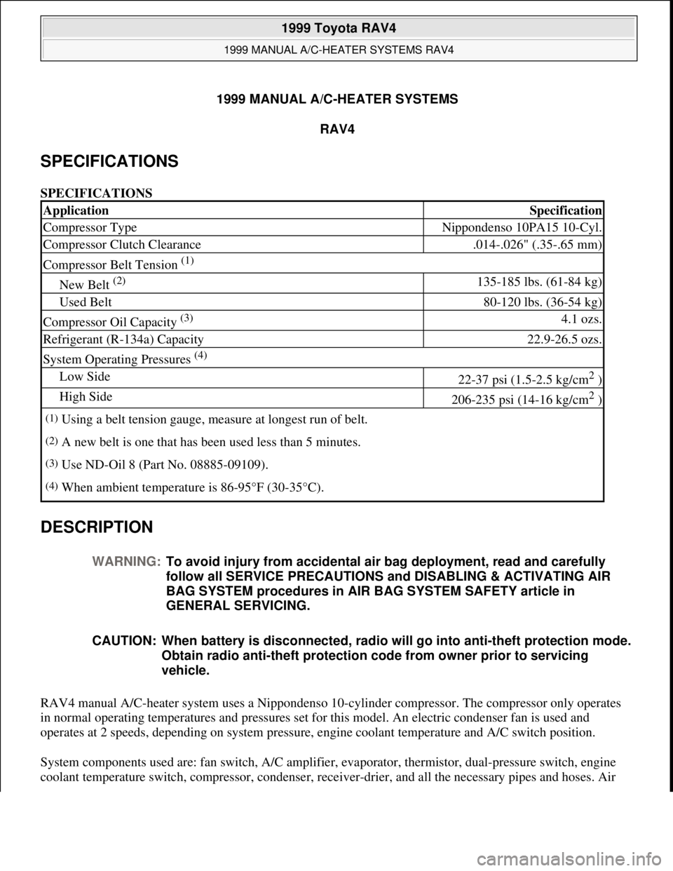
1999 MANUAL A/C-HEATER SYSTEMS
RAV4
SPECIFICATIONS
SPECIFICATIONS
DESCRIPTION
RAV4 manual A/C-heater system uses a Nippondenso 10-cylinder compressor. The compressor only operates
in normal operating temperatures and pressures set for this model. An electric condenser fan is used and
operates at 2 speeds, depending on system pressure, engine coolant temperature and A/C switch position.
System components used are: fan switch, A/C amplifier, evaporator, thermistor, dual-pressure switch, engine
coolant temperature switch, compressor, condenser, receive
r-drier, and all the necessary pipes and hoses. Air
ApplicationSpecification
Compressor TypeNippondenso 10PA15 10-Cyl.
Compressor Clutch Clearance.014-.026" (.35-.65 mm)
Compressor Belt Tension (1)
New Belt (2) 135-185 lbs. (61-84 kg)
Used Belt80-120 lbs. (36-54 kg)
Compressor Oil Capacity (3) 4.1 ozs.
Refrigerant (R-134a) Capacity22.9-26.5 ozs.
System Operating Pressures (4)
Low Side22-37 psi (1.5-2.5 kg/cm2 )
High Side206-235 psi (14-16 kg/cm2 )
(1)Using a belt tension gauge, measure at longest run of belt.
(2)A new belt is one that has been used less than 5 minutes.
(3)Use ND-Oil 8 (Part No. 08885-09109).
(4)When ambient temperature is 86-95°F (30-35°C).
WARNING:To avoid injury from accidental air bag deployment, read and carefully
follow all SERVICE PRECAUTIONS and DISABLING & ACTIVATING AIR
BAG SYSTEM procedures in AIR BAG SYSTEM SAFETY article in
GENERAL SERVICING.
CAUTION: When battery is disconnected, radio will go into anti-theft protection mode.
Obtain radio anti-theft protection code from owner prior to servicing
vehicle.
1999 Toyota RAV4
1999 MANUAL A/C-HEATER SYSTEMS RAV4
1999 Toyota RAV4
1999 MANUAL A/C-HEATER SYSTEMS RAV4
Microsoft
Sunday, November 22, 2009 10:29:27 AMPage 1 © 2005 Mitchell Repair Information Company, LLC.
Microsoft
Sunday, November 22, 2009 10:29:33 AMPage 1 © 2005 Mitchell Repair Information Company, LLC.
Page 950 of 1632
On models equipped with anti-lock brake systems, ALWAYS observe the following cautions:
DO NOT attempt to bleed hydraulic system without first referring to the appropriate ANTI-LOCK
BRAKE SYSTEM article in the BRAKES Section.
DO NOT mix tire sizes. As long as tires remain close to the original diameter, increasing the width is
acceptable. Rolling diameter must be identical for all 4 tires. Some manufacturers recommend tires of the
same brand, style and type. Failure to follow this precaution may cause inaccurate wheel speed readings.
Use ONLY recommended brake fluids. DO NOT use silicone brake fluids in an ABS-equipped vehicle.
BATTERY WARNING
REPLACING BLOWN FUSES
BRAKE PAD WEAR INDICATOR
Indicator will cause a squealing or scraping noise, warning that brake pads need replacement.
CATALYTIC CONVERTER CAUTION: The anti-lock brake system contains electronic equipment that can be
susceptible to interference caused by improperly installed or high output
radio transmitting equipment. Since this interference could cause the
possible loss of the anti-lock braking capability, such equipment should
be installed by qualified professionals.
WARNING:When battery is disconnected, vehicles equipped with computers may
lose memory data. When battery power is restored, driveability problems
may exist on some vehicles. These vehicles may require a relearn
procedure. See COMPUTER RELEARN PROCEDURES article in GENERAL
INFORMATION section.
CAUTION: Before replacing a blown fuse, remove ignition key, turn off all lights and
accessories to avoid damaging the electrical system. Be sure to use fuse
with the correct indicated amperage rating. The use of an incorrect
amperage rating fuse may result in a dangerous electrical system
overload.
CAUTION: Continued operation of vehicle with a severe malfunction could cause
converter to overheat, resulting in possible damage to converter and
vehicle.
CAUTION: Any modification to the exhaust system on turbo models, which reduces
exhaust backpressure, will lead to lean fuel mixtures and excessive spark
advance. This could cause serious engine damage.
1999 Toyota RAV4
MAINTENANCE INFORMATION 1997-99 MAINTENANCE Toyota Maintenance Information
Microsoft
Sunday, November 22, 2009 10:32:42 AMPage 8 © 2005 Mitchell Repair Information Company, LLC.
Page 968 of 1632
System
2 - DOME 15 Amp Personal Lights, Open Door Warning Light, Clock
3 - EFI 15 Amp Multiport Fuel Injection System/Sequential Multiport Fuel Injection System
4 - HAZ-HORN 15 Amp Emergency Flashers, Horns
5 - ALT-S 5 Amp Charging system
6 - SPARE 15 Amp Spare fuse
7 - SPARE 7.5 Amp Spare fues
8 - H-LP (LH) 15 Amp Left-Hand Headlight
9 - H-LP (RH) 15 Amp Right-Hand Headlight
10 - DRL 7.5 Amp Daytime Running Light System
11 - H-LP LH-L 10 Amp Left Hand Headlight (Low Beam)
12 - H-LP RH-L 10 Amp Right Hand Headlight (Low Beam)
13 - H-LP LH-H 10 Amp Left Hand Headlight (High Beam)
14 - H-LP RH-H 10 Amp Right Hand Headlight (High Beam)
15 - TAIL 10 Amp Tail Lights, Parking Lights, License Plate Lights, Interior Lights
16 - GAUGE 10 Amp Gauges And Meters, Service Reminder Indicators (Except Discharge And Open
Door Warning Lights), Back-up Lights, Air Conditioning System, Power Windows, Rear Window
Defogger, Center Differential Lock System, Electronically Controlled Automatic Transaxle System
17 - TURN 7.5 Amp Turn Signal Lights
18 - CIG & RAD 15 Amp Cigarette Lighter, Clock, Car Audio System, Power Rear View Mirrors
19 - DEF-I/UP 7.5 Amp Multiport Fuel Injection System/Sequential Multiport Fuel Injection System
20 - IGN 7.5 Amp Multiport Fuel Injection System/Sequential Multiport Fuel Injection System,
Discharge Warning Light
21 - ECU-IG 7.5 Amp Anti-Lock Brake Syste, Electronically Controlled Automatic Transmission
System
22 - WIPER 20 Amp Windshield Wipers And Washer, Rear Window Wiper And Washer
23 - SRS 7.5 Amp SRS Airbag System
24 - OBD 7.5 Amp On-Board Diagnostic System
25 - STOP 10 Amp Stop Lights
26 - A/C 7.5 Amp Air Conditioning System
27 - MAIN No. 1 30 Amp Starting System, Headlights
28 - RDI FAN 30 Amp Electric Cooling Fan
29 - CDS FAN 30 Amp Electric Cooling Fan
30 - POWER 30 Amp Power Windows, Power Door Lock System
31 - DEF 30 Amp Rear Window Defogger
32 - AM 1 40 Amp CIG & RAD, WIPER, GAUGE, ECU-IG, TURN, TAIL, and PANEL fuses
33 - MAIN 80 Amp AM 2, HAZ-HORN, EFI, DOME, RADIO and ALT-S fuses
34 - ALT 100 Amp Tail lights, ABS, RADIO, HTR, AM 1, POWER, STOP and DEF fuses
1999 Toyota RAV4
MAINTENANCE INFORMATION 1997-99 MAINTENANCE Toyota Maintenance Information
Microsoft
Sunday, November 22, 2009 10:32:42 AMPage 26 © 2005 Mitchell Repair Information Company, LLC.
Page 1612 of 1632
Fig. 27: Power Window Circuit, 4 Door
RADIO
1999 Toyota RAV4
1999 System Wiring Diagrams Toyota - RAV4
Microsoft
Sunday, November 22, 2009 10:50:58 AMPage 55 © 2005 Mitchell Repair Information Company, LLC.
Page 1614 of 1632
Fig. 28: Radio Circuits
SHIFT INTERLOCKS
1999 Toyota RAV4
1999 System Wiring Diagrams Toyota - RAV4
Microsoft
Sunday, November 22, 2009 10:50:58 AMPage 57 © 2005 Mitchell Repair Information Company, LLC.