TOYOTA RAV4 2006 Service Repair Manual
Manufacturer: TOYOTA, Model Year: 2006, Model line: RAV4, Model: TOYOTA RAV4 2006Pages: 2000, PDF Size: 45.84 MB
Page 1261 of 2000
U241E AUTOMATIC TRANSAXLE – AUTOMATIC TRANSAXLE SYSTEMAX–37
AX
CHECK MODE PROCEDURE
1. DESCRIPTION
(a) Check mode has a higher sensitivity to malfunctions
and can detect malfunctions that normal mode
cannot detect. Check mode can also detect all the
malfunctions that normal mode can detect. In check
mode, DTCs are detected with 1 trip detection logic.
2. CHECK MODE PROCEDURE
(a) Make sure that the following conditions below are
met:
(1) Battery positive voltage 11 V or more
(2) Throttle valve fully closed
(3) Transaxle in the P or N position
(4) A/C OFF
(b) Turn the ignition switch OFF.
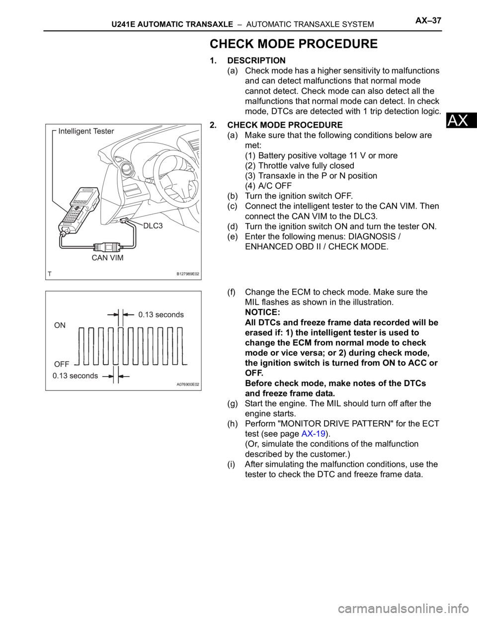
(c) Connect the intelligent tester to the CAN VIM. Then
connect the CAN VIM to the DLC3.
(d) Turn the ignition switch ON and turn the tester ON.
(e) Enter the following menus: DIAGNOSIS /
ENHANCED OBD II / CHECK MODE.
(f) Change the ECM to check mode. Make sure the
MIL flashes as shown in the illustration.
NOTICE:
All DTCs and freeze frame data recorded will be
erased if: 1) the intelligent tester is used to
change the ECM from normal mode to check
mode or vice versa; or 2) during check mode,
the ignition switch is turned from ON to ACC or
OFF.
Before check mode, make notes of the DTCs
and freeze frame data.
(g) Start the engine. The MIL should turn off after the
engine starts.
(h) Perform "MONITOR DRIVE PATTERN" for the ECT
test (see page AX-19).
(Or, simulate the conditions of the malfunction
described by the customer.)
(i) After simulating the malfunction conditions, use the
tester to check the DTC and freeze frame data.
B127989E02
A076900E02
Page 1262 of 2000
U241E AUTOMATIC TRANSAXLE – FLOOR SHIFT ASSEMBLYAX–139
AX
ADJUSTMENT
1. INSPECT SHIFT LEVER POSITION
(a) When shifting the lever from P to the R position with
the ignition switch ON and the brake pedal
depressed, make sure that the shift lever moves
smoothly and moves correctly into position.
(b) Start the engine and make sure that the vehicle
moves forward when shifting the lever from N to the
D position and moves rearward when shifting the
lever to the R position.
If the operation cannot be performed as specified,
inspect the park/neutral position switch assembly
and check the shift lever assembly installation
condition.
2. ADJUST SHIFT LEVER POSITION
(a) Shift the shift lever to the N position
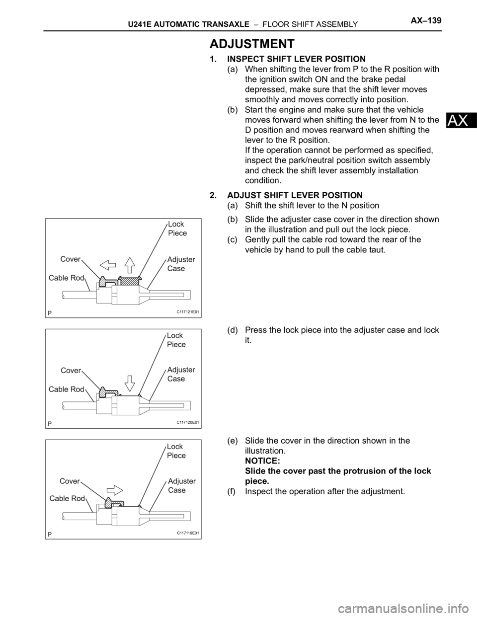
(b) Slide the adjuster case cover in the direction shown
in the illustration and pull out the lock piece.
(c) Gently pull the cable rod toward the rear of the
vehicle by hand to pull the cable taut.
(d) Press the lock piece into the adjuster case and lock
it.
(e) Slide the cover in the direction shown in the
illustration.
NOTICE:
Slide the cover past the protrusion of the lock
piece.
(f) Inspect the operation after the adjustment.
C117121E01
C117120E01
C117119E01
Page 1263 of 2000
AX–140U241E AUTOMATIC TRANSAXLE – FLOOR SHIFT ASSEMBLY
AX
REASSEMBLY
1. INSTALL SHIFT LOCK RELEASE BUTTON
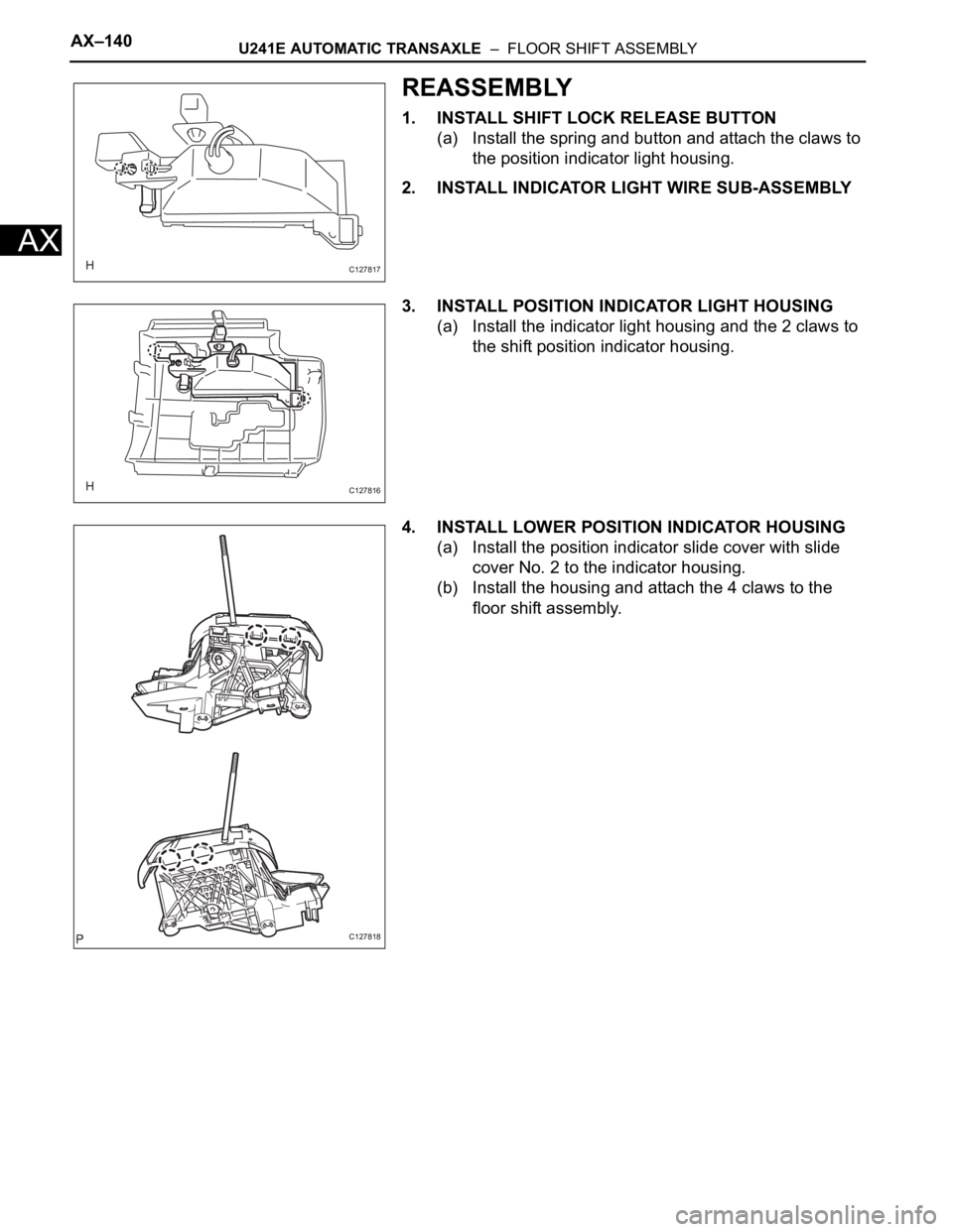
(a) Install the spring and button and attach the claws to
the position indicator light housing.
2. INSTALL INDICATOR LIGHT WIRE SUB-ASSEMBLY
3. INSTALL POSITION INDICATOR LIGHT HOUSING
(a) Install the indicator light housing and the 2 claws to
the shift position indicator housing.
4. INSTALL LOWER POSITION INDICATOR HOUSING
(a) Install the position indicator slide cover with slide
cover No. 2 to the indicator housing.
(b) Install the housing and attach the 4 claws to the
floor shift assembly.
C127817
C127816
C127818
Page 1264 of 2000
U241E AUTOMATIC TRANSAXLE – FLOOR SHIFT ASSEMBLYAX–141
AX
INSTALLATION
1. INSTALL FLOOR SHIFT ASSEMBLY
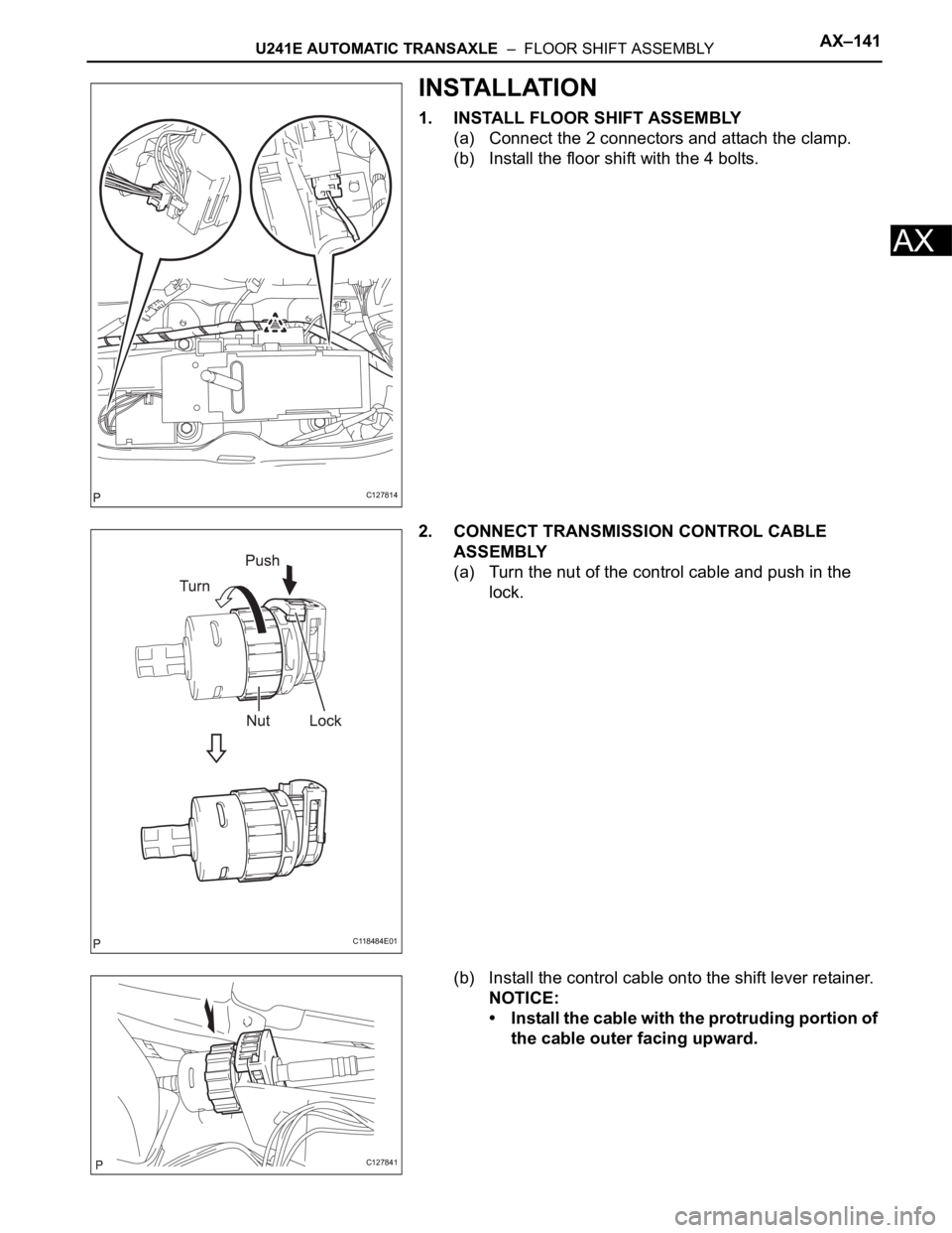
(a) Connect the 2 connectors and attach the clamp.
(b) Install the floor shift with the 4 bolts.
2. CONNECT TRANSMISSION CONTROL CABLE
ASSEMBLY
(a) Turn the nut of the control cable and push in the
lock.
(b) Install the control cable onto the shift lever retainer.
NOTICE:
• Install the cable with the protruding portion of
the cable outer facing upward.
C127814
C118484E01
C127841
Page 1265 of 2000
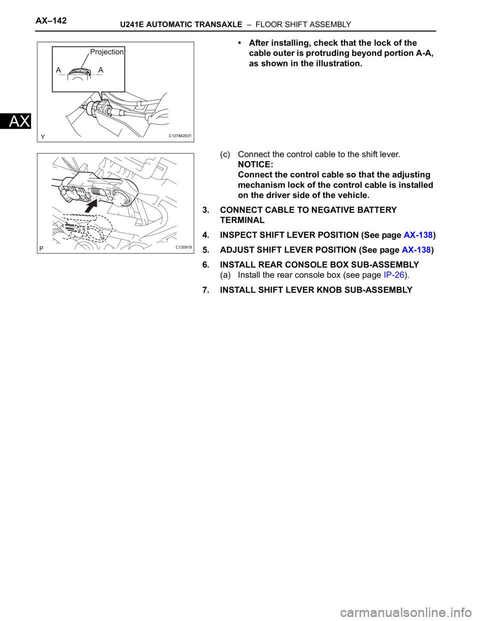
AX–142U241E AUTOMATIC TRANSAXLE – FLOOR SHIFT ASSEMBLY
AX
• After installing, check that the lock of the
cable outer is protruding beyond portion A-A,
as shown in the illustration.
(c) Connect the control cable to the shift lever.
NOTICE:
Connect the control cable so that the adjusting
mechanism lock of the control cable is installed
on the driver side of the vehicle.
3. CONNECT CABLE TO NEGATIVE BATTERY
TERMINAL
4. INSPECT SHIFT LEVER POSITION (See page AX-138)
5. ADJUST SHIFT LEVER POSITION (See page AX-138)
6. INSTALL REAR CONSOLE BOX SUB-ASSEMBLY
(a) Install the rear console box (see page IP-26).
7. INSTALL SHIFT LEVER KNOB SUB-ASSEMBLY
C127842E01
C130919
Page 1266 of 2000
U241E AUTOMATIC TRANSAXLE – AUTOMATIC TRANSAXLE ASSEMBLYAX–149
AX
INSTALLATION
1. INSPECT TORQUE CONVERTER CLUTCH
ASSEMBLY
(a) Inspect the torque converter (see page AX-152).
2. INSTALL TORQUE CONVERTER CLUTCH
ASSEMBLY
(a) Install the torque converter clutch to the automatic
transaxle.
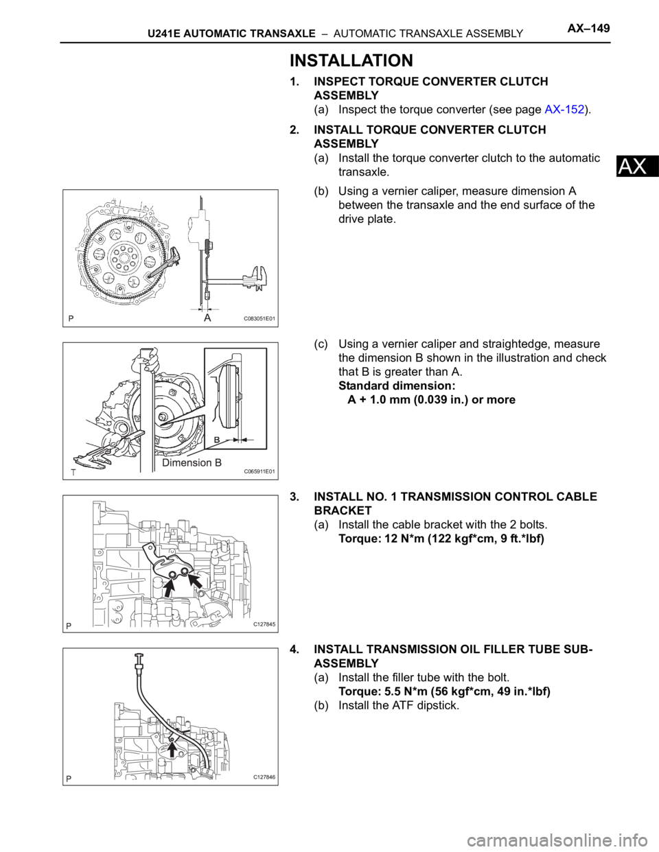
(b) Using a vernier caliper, measure dimension A
between the transaxle and the end surface of the
drive plate.
(c) Using a vernier caliper and straightedge, measure
the dimension B shown in the illustration and check
that B is greater than A.
Standard dimension:
A + 1.0 mm (0.039 in.) or more
3. INSTALL NO. 1 TRANSMISSION CONTROL CABLE
BRACKET
(a) Install the cable bracket with the 2 bolts.
Torque: 12 N*m (122 kgf*cm, 9 ft.*lbf)
4. INSTALL TRANSMISSION OIL FILLER TUBE SUB-
ASSEMBLY
(a) Install the filler tube with the bolt.
Torque: 5.5 N*m (56 kgf*cm, 49 in.*lbf)
(b) Install the ATF dipstick.
C083051E01
C065911E01
C127845
C127846
Page 1267 of 2000
AX–150U241E AUTOMATIC TRANSAXLE – AUTOMATIC TRANSAXLE ASSEMBLY
AX
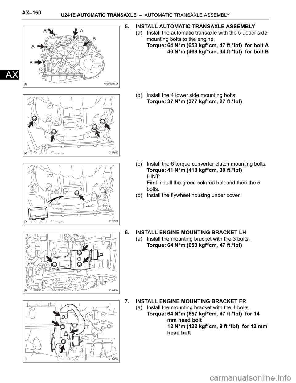
5. INSTALL AUTOMATIC TRANSAXLE ASSEMBLY
(a) Install the automatic transaxle with the 5 upper side
mounting bolts to the engine.
Torque: 64 N*m (653 kgf*cm, 47 ft.*lbf) for bolt A
46 N*m (469 kgf*cm, 34 ft.*lbf) for bolt B
(b) Install the 4 lower side mounting bolts.
Torque: 37 N*m (377 kgf*cm, 27 ft.*lbf)
(c) Install the 6 torque converter clutch mounting bolts.
Torque: 41 N*m (418 kgf*cm, 30 ft.*lbf)
HINT:
First install the green colored bolt and then the 5
bolts.
(d) Install the flywheel housing under cover.
6. INSTALL ENGINE MOUNTING BRACKET LH
(a) Install the mounting bracket with the 3 bolts.
Torque: 64 N*m (653 kgf*cm, 47 ft.*lbf)
7. INSTALL ENGINE MOUNTING BRACKET FR
(a) Install the mounting bracket with the 4 bolts.
Torque: 64 N*m (657 kgf*cm, 47 ft.*lbf) for 14
mm head bolt
12 N*m (122 kgf*cm, 9 ft.*lbf) for 12 mm
head bolt
C127822E01
C127820
C129381
C129380
C130912
Page 1268 of 2000
U241E AUTOMATIC TRANSAXLE – AUTOMATIC TRANSAXLE ASSEMBLYAX–151
AX
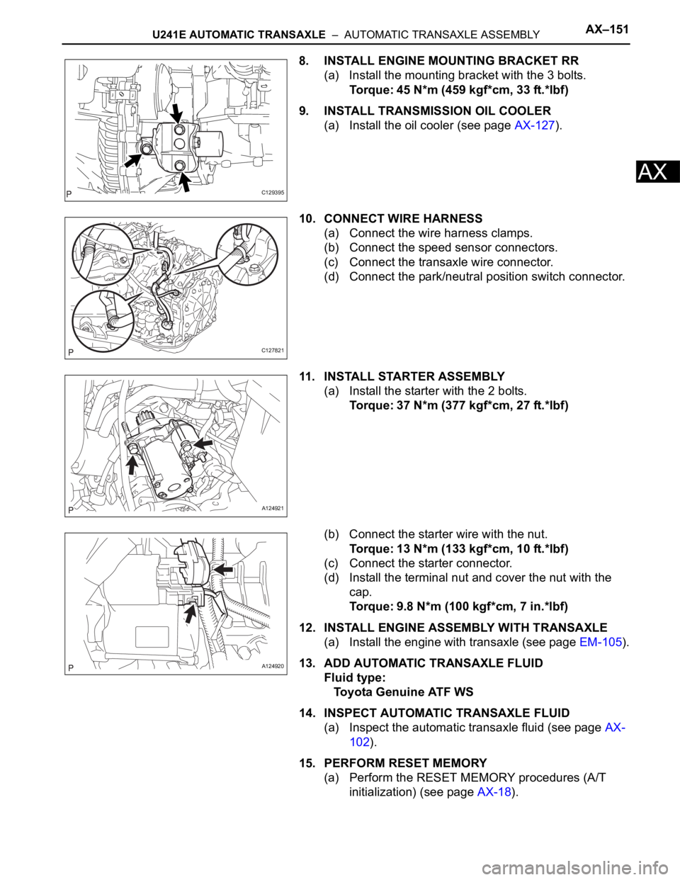
8. INSTALL ENGINE MOUNTING BRACKET RR
(a) Install the mounting bracket with the 3 bolts.
Torque: 45 N*m (459 kgf*cm, 33 ft.*lbf)
9. INSTALL TRANSMISSION OIL COOLER
(a) Install the oil cooler (see page AX-127).
10. CONNECT WIRE HARNESS
(a) Connect the wire harness clamps.
(b) Connect the speed sensor connectors.
(c) Connect the transaxle wire connector.
(d) Connect the park/neutral position switch connector.
11. INSTALL STARTER ASSEMBLY
(a) Install the starter with the 2 bolts.
Torque: 37 N*m (377 kgf*cm, 27 ft.*lbf)
(b) Connect the starter wire with the nut.
Torque: 13 N*m (133 kgf*cm, 10 ft.*lbf)
(c) Connect the starter connector.
(d) Install the terminal nut and cover the nut with the
cap.
Torque: 9.8 N*m (100 kgf*cm, 7 in.*lbf)
12. INSTALL ENGINE ASSEMBLY WITH TRANSAXLE
(a) Install the engine with transaxle (see page EM-105).
13. ADD AUTOMATIC TRANSAXLE FLUID
Fluid type:
Toyota Genuine ATF WS
14. INSPECT AUTOMATIC TRANSAXLE FLUID
(a) Inspect the automatic transaxle fluid (see page AX-
102).
15. PERFORM RESET MEMORY
(a) Perform the RESET MEMORY procedures (A/T
initialization) (see page AX-18).
C129395
C127821
A124921
A124920
Page 1269 of 2000
U241E AUTOMATIC TRANSAXLE – AUTOMATIC TRANSAXLE UNITAX–165
AX
DISASSEMBLY
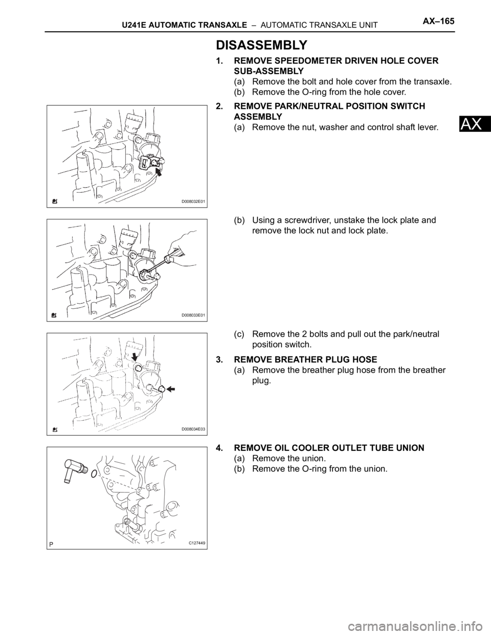
1. REMOVE SPEEDOMETER DRIVEN HOLE COVER
SUB-ASSEMBLY
(a) Remove the bolt and hole cover from the transaxle.
(b) Remove the O-ring from the hole cover.
2. REMOVE PARK/NEUTRAL POSITION SWITCH
ASSEMBLY
(a) Remove the nut, washer and control shaft lever.
(b) Using a screwdriver, unstake the lock plate and
remove the lock nut and lock plate.
(c) Remove the 2 bolts and pull out the park/neutral
position switch.
3. REMOVE BREATHER PLUG HOSE
(a) Remove the breather plug hose from the breather
plug.
4. REMOVE OIL COOLER OUTLET TUBE UNION
(a) Remove the union.
(b) Remove the O-ring from the union.
D008032E01
D008033E01
D008034E03
C127449
Page 1270 of 2000
AX–166U241E AUTOMATIC TRANSAXLE – AUTOMATIC TRANSAXLE UNIT
AX
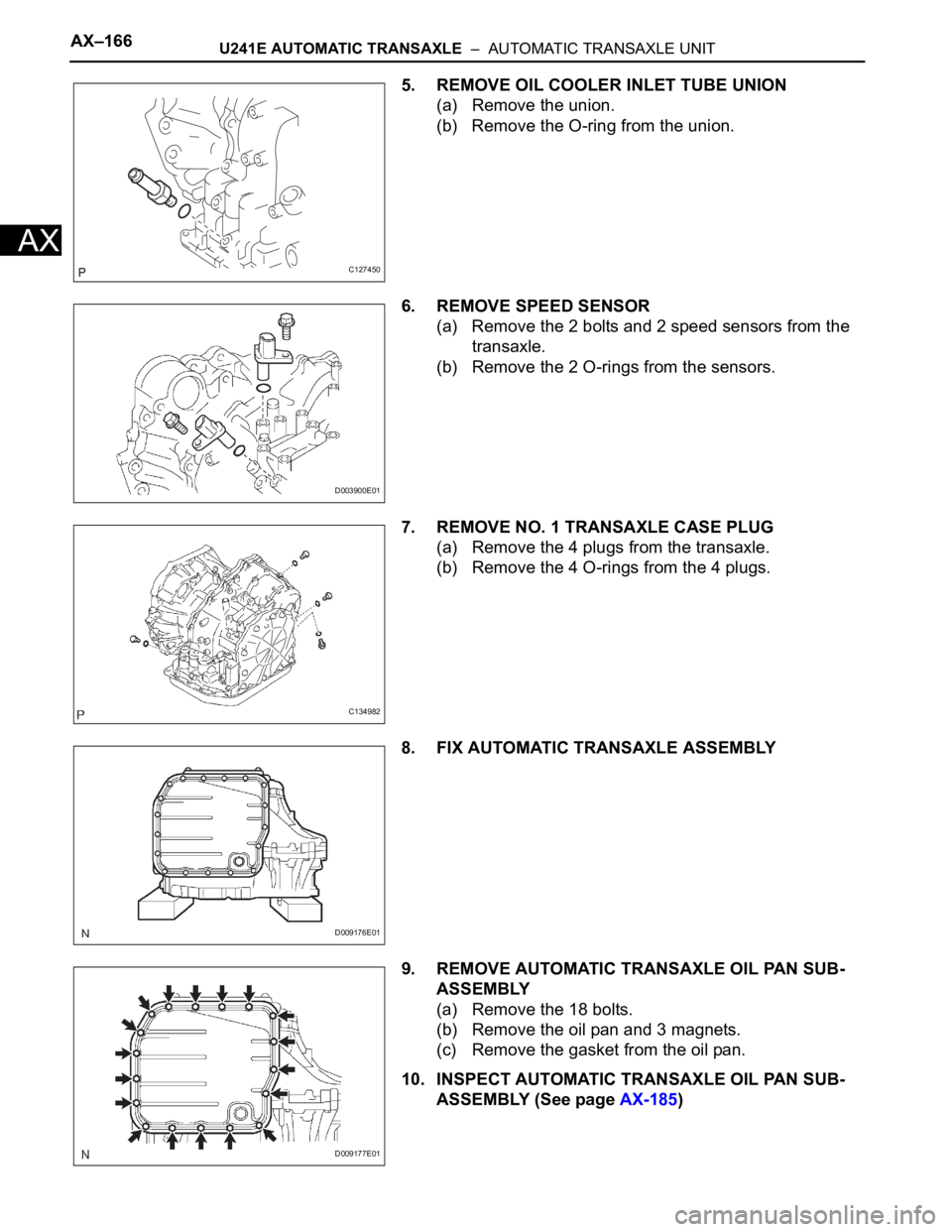
5. REMOVE OIL COOLER INLET TUBE UNION
(a) Remove the union.
(b) Remove the O-ring from the union.
6. REMOVE SPEED SENSOR
(a) Remove the 2 bolts and 2 speed sensors from the
transaxle.
(b) Remove the 2 O-rings from the sensors.
7. REMOVE NO. 1 TRANSAXLE CASE PLUG
(a) Remove the 4 plugs from the transaxle.
(b) Remove the 4 O-rings from the 4 plugs.
8. FIX AUTOMATIC TRANSAXLE ASSEMBLY
9. REMOVE AUTOMATIC TRANSAXLE OIL PAN SUB-
ASSEMBLY
(a) Remove the 18 bolts.
(b) Remove the oil pan and 3 magnets.
(c) Remove the gasket from the oil pan.
10. INSPECT AUTOMATIC TRANSAXLE OIL PAN SUB-
ASSEMBLY (See page AX-185)
C127450
D003900E01
C134982
D009176E01
D009177E01