TOYOTA RAV4 2006 Service Repair Manual
Manufacturer: TOYOTA, Model Year: 2006, Model line: RAV4, Model: TOYOTA RAV4 2006Pages: 2000, PDF Size: 45.84 MB
Page 1491 of 2000

TIRE AND WHEEL – TIRE PRESSURE WARNING SYSTEMTW–19
TW
TERMINALS OF ECU
1. CHECK TIRE PRESSURE WARNING ECU
(a) Disconnect the E56 ECU connector.
(b) Measure the voltage and resistance of the wire
harness side connector.
If the result is not as specified, there may be a
malfunction on the wire harness side.
(c) Reconnect the E56 ECU connector.
(d) Measure the voltage of the connector.
If the result is not as specified, the ECU may have a
malfunction.
F101021E01
Symbols (Terminal No.) Wiring Color Terminal Description ConditionSpecified Condition
IG (E56-2) - GND (E56-
11 )L - W-B IG power source Ignition switch ON 10 to 14 V
Ignition switch OFF Below 1 V
GND (E56-11) - Body
groundW-B - Body ground Ground Always Below 1
Symbols (Terminal No.) Wiring Color Terminal Description ConditionSpecified Condition
SPD (E56-3) - GND (E56-
11 )V - W-B Vehicle speed signal Vehicle is running Pulse generation
SIL (E56-4) - GND (E56-
11 )W - W-B Diagnosis tester
communication lineIgnition switch ON,
when communication is
not performed with a tester8 to 15 V
IND (E56-6) - GND (E56-
11 )P - W-B Tire pressure warning light
output signalIgnition switch ON,
tire pressure warning light
ONBelow 1 V
RDA (E56-7) - GND (E56-
11 )G - W-B Tire pressure monitor
receiver signalIgnition switch ON,
tire pressure monitor
receiver is not connected9 to 16 V
RFSV (E56-8) - GND
(E56-11)R - W-B Tire pressure monitor
receiver power sourceIgnition switch ON 4.5 to 5.5 V
TC (E56-12) - GND (E56-
11 )G - W-B TC terminal When terminal TC is not
connected8 to 15 V
GND2 (E56-16) - Body
groundY - Body ground Tire pressure monitor
receiver groundAlways Below 1 V
Page 1492 of 2000
TW–20TIRE AND WHEEL – TIRE PRESSURE WARNING SYSTEM
TW
DIAGNOSIS SYSTEM
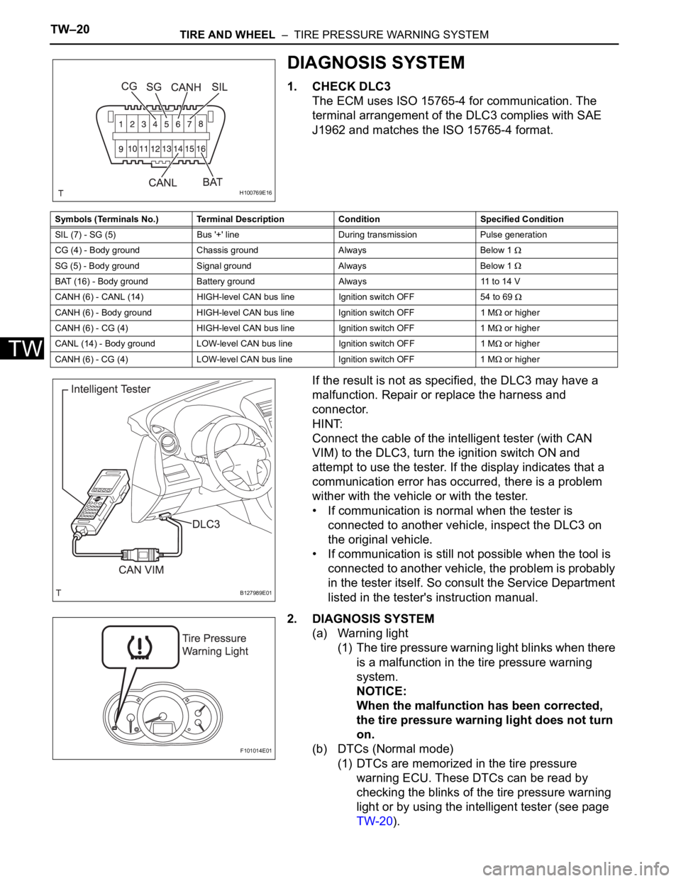
1. CHECK DLC3
The ECM uses ISO 15765-4 for communication. The
terminal arrangement of the DLC3 complies with SAE
J1962 and matches the ISO 15765-4 format.
If the result is not as specified, the DLC3 may have a
malfunction. Repair or replace the harness and
connector.
HINT:
Connect the cable of the intelligent tester (with CAN
VIM) to the DLC3, turn the ignition switch ON and
attempt to use the tester. If the display indicates that a
communication error has occurred, there is a problem
wither with the vehicle or with the tester.
• If communication is normal when the tester is
connected to another vehicle, inspect the DLC3 on
the original vehicle.
• If communication is still not possible when the tool is
connected to another vehicle, the problem is probably
in the tester itself. So consult the Service Department
listed in the tester's instruction manual.
2. DIAGNOSIS SYSTEM
(a) Warning light
(1) The tire pressure warning light blinks when there
is a malfunction in the tire pressure warning
system.
NOTICE:
When the malfunction has been corrected,
the tire pressure warning light does not turn
on.
(b) DTCs (Normal mode)
(1) DTCs are memorized in the tire pressure
warning ECU. These DTCs can be read by
checking the blinks of the tire pressure warning
light or by using the intelligent tester (see page
TW-20).
H100769E16
Symbols (Terminals No.) Terminal Description Condition Specified Condition
SIL (7) - SG (5) Bus '+' line During transmission Pulse generation
CG (4) - Body ground Chassis ground Always Below 1
SG (5) - Body ground Signal ground Always Below 1
BAT (16) - Body ground Battery ground Always 11 to 14 V
CANH (6) - CANL (14) HIGH-level CAN bus line Ignition switch OFF 54 to 69
CANH (6) - Body ground HIGH-level CAN bus line Ignition switch OFF1 M or higher
CANH (6) - CG (4) HIGH-level CAN bus line Ignition switch OFF 1 M
or higher
CANL (14) - Body ground LOW-level CAN bus line Ignition switch OFF1 M
or higher
CANH (6) - CG (4) LOW-level CAN bus line Ignition switch OFF 1 M
or higher
B127989E01
F101014E01
Page 1493 of 2000
TIRE AND WHEEL – TIRE PRESSURE WARNING SYSTEMTW–21
TW
(c) Test mode
(1) By switching from normal mode to test mode
(input signal check), you can inspect the tire
pressure monitor receiver, each tire pressure
warning valve and transmitter and vehicle speed
sensor (see page TW-12).
3. CHECK TIRE PRESSURE WARNING LIGHT
(a) Turn the ignition switch ON.
(b) Check that the tire pressure warning light turns on
for 3 seconds.
If the warning check result is not normal, proceed to
the troubleshooting for the tire pressure warning
light circuit.
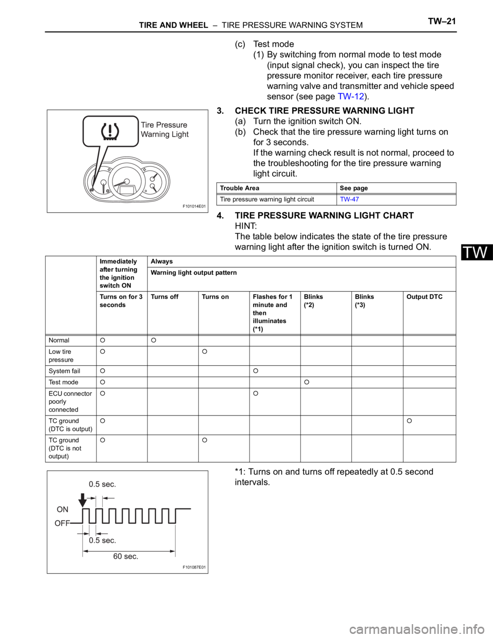
4. TIRE PRESSURE WARNING LIGHT CHART
HINT:
The table below indicates the state of the tire pressure
warning light after the ignition switch is turned ON.
*1: Turns on and turns off repeatedly at 0.5 second
intervals.
F101014E01
Trouble Area See page
Tire pressure warning light circuitTW-47
Immediately
after turning
the ignition
switch ONAlways
Warning light output pattern
Turns on for 3
secondsTurns off Turns on Flashes for 1
minute and
then
illuminates
(*1)Blinks
(*2)Blinks
(*3)Output DTC
Normal
Low tire
pressure
System fail
Te s t m o d e
ECU connector
poorly
connected
TC ground
(DTC is output)
TC ground
(DTC is not
output)
F101087E01
Page 1494 of 2000
TW–22TIRE AND WHEEL – TIRE PRESSURE WARNING SYSTEM
TW
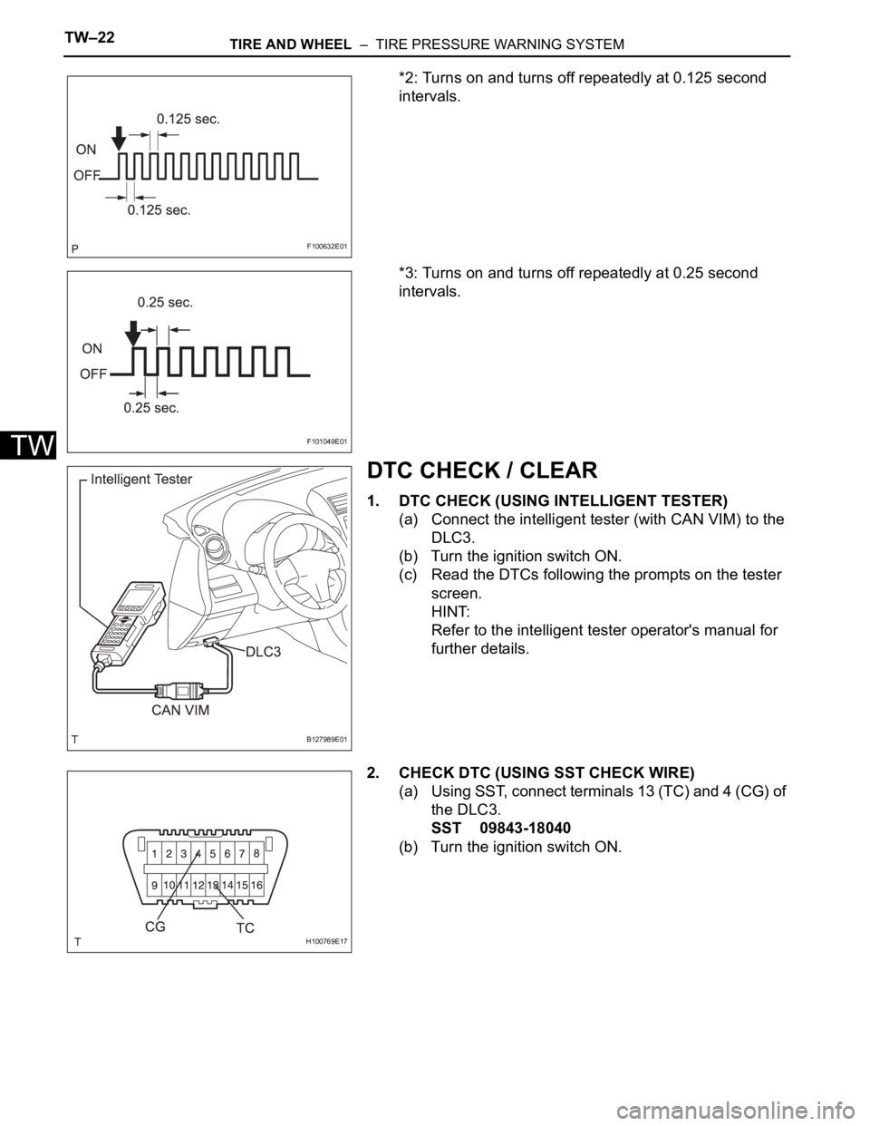
*2: Turns on and turns off repeatedly at 0.125 second
intervals.
*3: Turns on and turns off repeatedly at 0.25 second
intervals.
DTC CHECK / CLEAR
1. DTC CHECK (USING INTELLIGENT TESTER)
(a) Connect the intelligent tester (with CAN VIM) to the
DLC3.
(b) Turn the ignition switch ON.
(c) Read the DTCs following the prompts on the tester
screen.
HINT:
Refer to the intelligent tester operator's manual for
further details.
2. CHECK DTC (USING SST CHECK WIRE)
(a) Using SST, connect terminals 13 (TC) and 4 (CG) of
the DLC3.
SST 09843-18040
(b) Turn the ignition switch ON.
F100632E01
F101049E01
B127989E01
H100769E17
Page 1495 of 2000
TIRE AND WHEEL – TIRE PRESSURE WARNING SYSTEMTW–23
TW
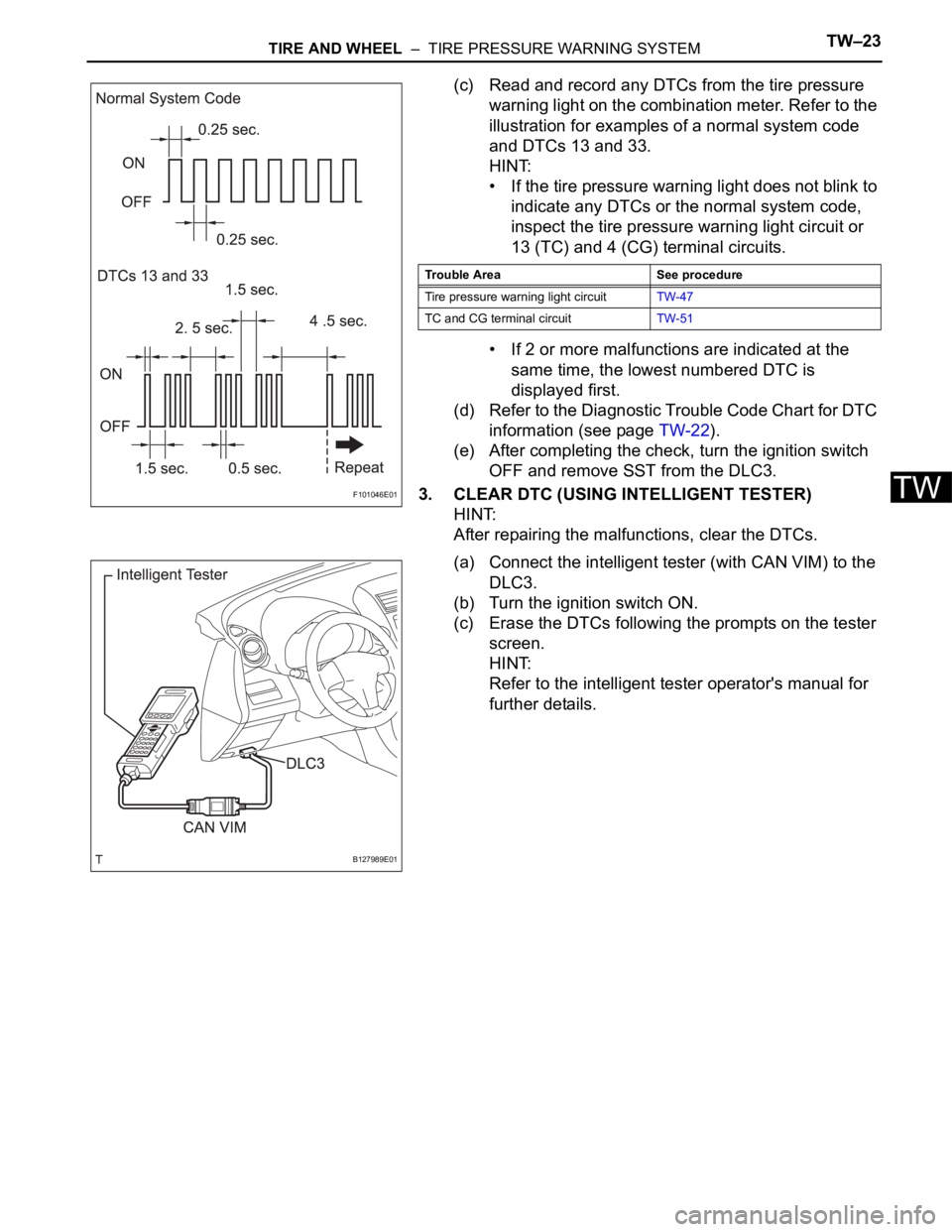
(c) Read and record any DTCs from the tire pressure
warning light on the combination meter. Refer to the
illustration for examples of a normal system code
and DTCs 13 and 33.
HINT:
• If the tire pressure warning light does not blink to
indicate any DTCs or the normal system code,
inspect the tire pressure warning light circuit or
13 (TC) and 4 (CG) terminal circuits.
• If 2 or more malfunctions are indicated at the
same time, the lowest numbered DTC is
displayed first.
(d) Refer to the Diagnostic Trouble Code Chart for DTC
information (see page TW-22).
(e) After completing the check, turn the ignition switch
OFF and remove SST from the DLC3.
3. CLEAR DTC (USING INTELLIGENT TESTER)
HINT:
After repairing the malfunctions, clear the DTCs.
(a) Connect the intelligent tester (with CAN VIM) to the
DLC3.
(b) Turn the ignition switch ON.
(c) Erase the DTCs following the prompts on the tester
screen.
HINT:
Refer to the intelligent tester operator's manual for
further details.
F101046E01
Trouble Area See procedure
Tire pressure warning light circuitTW-47
TC and CG terminal circuitTW-51
B127989E01
Page 1496 of 2000

TW–24TIRE AND WHEEL – TIRE PRESSURE WARNING SYSTEM
TW
DATA LIST / ACTIVE TEST
1. READ DATA LIST
HINT:
Using the intelligent tester's DATA LIST allows switch,
actuator and other item values to be read without
removing any parts. Reading the Data List early in
troubleshooting is one way to save time.
(a) Connect the intelligent tester (with CAN VIM) to the
DLC3.
(b) Turn the ignition switch ON.
(c) Read the DATA LIST according to the display on the
tester.
Tire pressure warning ECU
Item Measurement item/ Range
(Display)Normal Condition Diagnostic Note
MODE STATUS Tire pressure warning system
mode / NORMAL or REG 2nd or
REG M or TEST NORMAL: Normal mode TEST:
Test mode
REG 2nd: 2nd registration
REG M: Main registration
TEST: Test mode -
MAIN TIRE Number of main tire IDs to be
registered / 0 or 1 or 2 or 3 or 4
or 5 0 to 5 should be displayed -
VEHICLE SPEED Vehicle speed reading /
min.: 0 km/h (0 mph),
max.: 255 km/h (158 mph)Actual vehicle speed Speed indicated on the
combination meter
REGIT ID1 CODE Registered ID1 code / min.: 0,
max.: FFFFFFF The ID No. registered in
transmitter ID1 is displayed -
REGIT ID2 CODE Registered ID2 code / min.: 0,
max.: FFFFFFF The ID No. registered in
transmitter ID2 is displayed -
REGIT ID3 CODE Registered ID3 code / min.: 0,
max.: FFFFFFF The ID No. registered in
transmitter ID3 is displayed -
REGIT ID4 CODE Registered ID4 code / min.: 0,
max.: FFFFFFF The ID No. registered in
transmitter ID4 is displayed -
REGIT ID5 CODE Registered ID5 code / min.: 0,
max.: FFFFFFF The ID No. registered in
transmitter ID5 is displayed -
TRANS STATUS ID code transmission status /
FINISH or NOW FINISH or NOW -
TIREPRESS1 ID1 tire pressure /
min.: 0 kPa (0 kgf/cm
2, 0 psi)
max.: 637.5 kPa (6.48 kgf/cm2,
92.2 psi) Actual tire pressure -
TIREPRESS2 ID2 tire pressure /
min.: 0 kPa (0 kgf/cm
2, 0 psi)
max.: 637.5 kPa (6.48 kgf/cm2,
92.2 psi) Actual tire pressure -
TIREPRESS3 ID3 tire pressure /
min.: 0 kPa (0 kgf/cm
2, 0 psi)
max.: 637.5 kPa (6.48 kgf/cm2,
92.2 psi) Actual tire pressure -
TIREPRESS4 ID4 tire pressure /
min.: 0 kPa (0 kgf/cm
2, 0 psi)
max.: 637.5 kPa (6.48 kgf/cm2,
92.2 psi) Actual tire pressure -
TIREPRESS5 ID5 tire pressure /
min.: 0 kPa (0 kgf/cm
2, 0 psi)
max.: 637.5 kPa (6.48 kgf/cm2,
92.2 psi) Actual tire pressure -
Page 1497 of 2000

TIRE AND WHEEL – TIRE PRESSURE WARNING SYSTEMTW–25
TW
TIRE TEMP1 ID1 temperature in tire /
min.: -40C (-40F)
max.: 215
C (419F)Actual tire temperature -
TIRE TEMP2 ID2 temperature in tire /
min.: -40
C (-40F)
max.: 215
C (419F)Actual tire temperature -
TIRE TEMP3 ID3 temperature in tire /
min.: -40
C (-40F)
max.: 215C (419F)Actual tire temperature -
TIRE TEMP4 ID4 temperature in tire /
min.: -40
C (-40F)
max.: 215
C (419F)Actual tire temperature -
TIRE TEMP5 ID5 temperature in tire /
min.: -40
C (-40F)
max.: 215
C (419F)Actual tire temperature -
BATT VOLT1 ID1 battery voltage / OVER or
LESSOVER -
BATT VOLT2 ID2 battery voltage / OVER or
LESSOVER -
BATT VOLT3 ID3 battery voltage / OVER or
LESSOVER -
BATT VOLT4 ID4 battery voltage / OVER or
LESSOVER -
BATT VOLT5 ID5 battery voltage / OVER or
LESSOVER -
# CODES Number of DTC recorded/
min.: 0
max.: 255Min.: 0
Max.: -- Item Measurement item/ Range
(Display)Normal Condition Diagnostic Note
Page 1498 of 2000
TW–26TIRE AND WHEEL – TIRE PRESSURE WARNING SYSTEM
TW
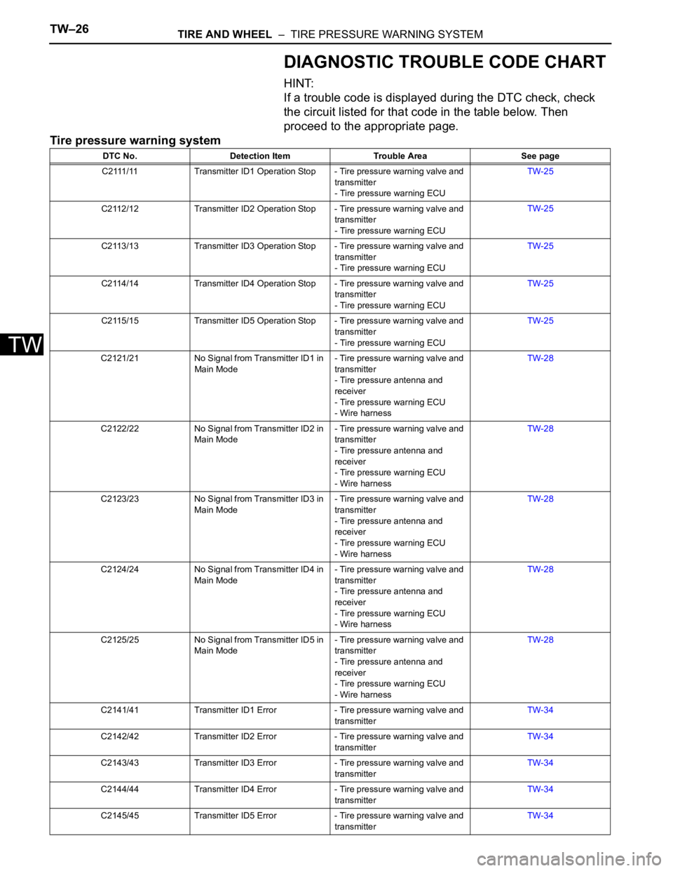
DIAGNOSTIC TROUBLE CODE CHART
HINT:
If a trouble code is displayed during the DTC check, check
the circuit listed for that code in the table below. Then
proceed to the appropriate page.
Tire pressure warning system
DTC No. Detection Item Trouble Area See page
C2111/11 Transmitter ID1 Operation Stop - Tire pressure warning valve and
transmitter
- Tire pressure warning ECUTW-25
C2112/12 Transmitter ID2 Operation Stop - Tire pressure warning valve and
transmitter
- Tire pressure warning ECUTW-25
C2113/13 Transmitter ID3 Operation Stop - Tire pressure warning valve and
transmitter
- Tire pressure warning ECUTW-25
C2114/14 Transmitter ID4 Operation Stop - Tire pressure warning valve and
transmitter
- Tire pressure warning ECUTW-25
C2115/15 Transmitter ID5 Operation Stop - Tire pressure warning valve and
transmitter
- Tire pressure warning ECUTW-25
C2121/21 No Signal from Transmitter ID1 in
Main Mode- Tire pressure warning valve and
transmitter
- Tire pressure antenna and
receiver
- Tire pressure warning ECU
- Wire harnessTW-28
C2122/22 No Signal from Transmitter ID2 in
Main Mode- Tire pressure warning valve and
transmitter
- Tire pressure antenna and
receiver
- Tire pressure warning ECU
- Wire harnessTW-28
C2123/23 No Signal from Transmitter ID3 in
Main Mode- Tire pressure warning valve and
transmitter
- Tire pressure antenna and
receiver
- Tire pressure warning ECU
- Wire harnessTW-28
C2124/24 No Signal from Transmitter ID4 in
Main Mode- Tire pressure warning valve and
transmitter
- Tire pressure antenna and
receiver
- Tire pressure warning ECU
- Wire harnessTW-28
C2125/25 No Signal from Transmitter ID5 in
Main Mode- Tire pressure warning valve and
transmitter
- Tire pressure antenna and
receiver
- Tire pressure warning ECU
- Wire harnessTW-28
C2141/41 Transmitter ID1 Error - Tire pressure warning valve and
transmitterTW-34
C2142/42 Transmitter ID2 Error - Tire pressure warning valve and
transmitterTW-34
C2143/43 Transmitter ID3 Error - Tire pressure warning valve and
transmitterTW-34
C2144/44 Transmitter ID4 Error - Tire pressure warning valve and
transmitterTW-34
C2145/45 Transmitter ID5 Error - Tire pressure warning valve and
transmitterTW-34
Page 1499 of 2000
TIRE AND WHEEL – TIRE PRESSURE WARNING SYSTEMTW–27
TW
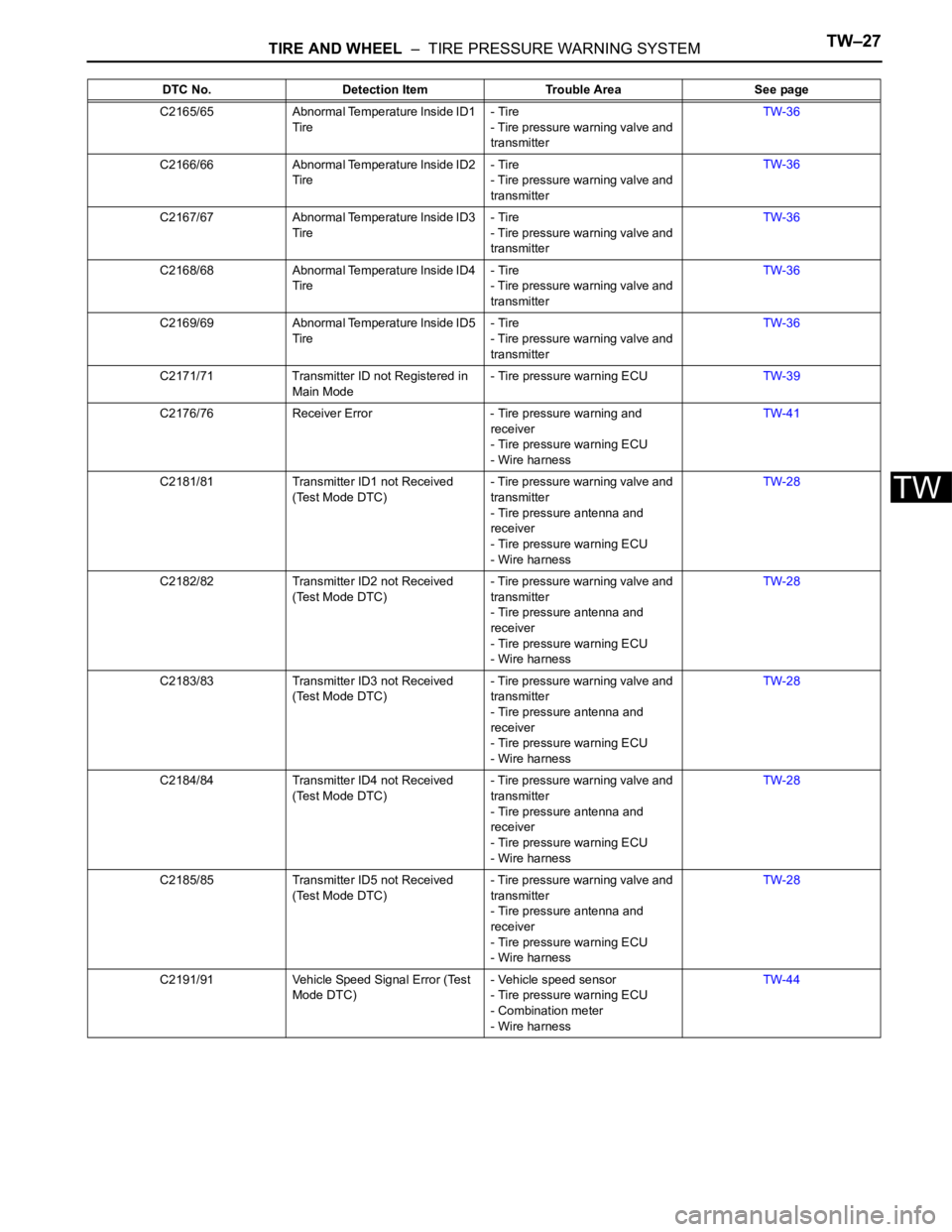
C2165/65 Abnormal Temperature Inside ID1
Tire- Tire
- Tire pressure warning valve and
transmitterTW-36
C2166/66 Abnormal Temperature Inside ID2
Tire- Tire
- Tire pressure warning valve and
transmitterTW-36
C2167/67 Abnormal Temperature Inside ID3
Tire- Tire
- Tire pressure warning valve and
transmitterTW-36
C2168/68 Abnormal Temperature Inside ID4
Tire- Tire
- Tire pressure warning valve and
transmitterTW-36
C2169/69 Abnormal Temperature Inside ID5
Tire- Tire
- Tire pressure warning valve and
transmitterTW-36
C2171/71 Transmitter ID not Registered in
Main Mode- Tire pressure warning ECUTW-39
C2176/76 Receiver Error - Tire pressure warning and
receiver
- Tire pressure warning ECU
- Wire harnessTW-41
C2181/81 Transmitter ID1 not Received
(Test Mode DTC)- Tire pressure warning valve and
transmitter
- Tire pressure antenna and
receiver
- Tire pressure warning ECU
- Wire harnessTW-28
C2182/82 Transmitter ID2 not Received
(Test Mode DTC)- Tire pressure warning valve and
transmitter
- Tire pressure antenna and
receiver
- Tire pressure warning ECU
- Wire harnessTW-28
C2183/83 Transmitter ID3 not Received
(Test Mode DTC)- Tire pressure warning valve and
transmitter
- Tire pressure antenna and
receiver
- Tire pressure warning ECU
- Wire harnessTW-28
C2184/84 Transmitter ID4 not Received
(Test Mode DTC)- Tire pressure warning valve and
transmitter
- Tire pressure antenna and
receiver
- Tire pressure warning ECU
- Wire harnessTW-28
C2185/85 Transmitter ID5 not Received
(Test Mode DTC)- Tire pressure warning valve and
transmitter
- Tire pressure antenna and
receiver
- Tire pressure warning ECU
- Wire harnessTW-28
C2191/91 Vehicle Speed Signal Error (Test
Mode DTC)- Vehicle speed sensor
- Tire pressure warning ECU
- Combination meter
- Wire harnessTW-44 DTC No. Detection Item Trouble Area See page
Page 1500 of 2000

TW–28TIRE AND WHEEL – TIRE PRESSURE WARNING SYSTEM
TW
DESCRIPTION
The tire pressure warning valve and transmitter that is installed in the tires and wheels measures the air
pressure of the tires. The measured values are transmitted to the tire pressure warning receiver on the
body as radio waves and then sent to the tire pressure warning ECU. The ECU compares the measured
air pressure values with the air pressure threshold. When the measured air pressure values are less than
this threshold, the warning light in the combination meter turns on.
The tire pressure warning ECU stores a DTC when the tire pressure monitor valve stops transmitting
signals. At this time, forcibly transmit the signals by releasing the tire pressure rapidly. The stored DTC is
cleared when the signal transmission is resumed.
HINT:
It is necessary to perform the procedure to identify the tire pressure monitor valve that is malfunctioning
because it cannot be identified by the output DTC.
DTC C2111/11 Transmitter ID1 Operation Stop
DTC C2112/12 Transmitter ID2 Operation Stop
DTC C2113/13 Transmitter ID3 Operation Stop
DTC C2114/14 Transmitter ID4 Operation Stop
DTC C2115/15 Transmitter ID5 Operation Stop
DTC No DTC Detection Condition Trouble Area
C 2 111 / 11
C2112/12
C2113/13
C2114/14
C2115/15Tire pressure monitor valve stops transmitting
signals• Tire pressure warning valve and
transmitter
• Tire pressure warning ECU