TOYOTA RAV4 2006 Service Repair Manual
Manufacturer: TOYOTA, Model Year: 2006, Model line: RAV4, Model: TOYOTA RAV4 2006Pages: 2000, PDF Size: 45.84 MB
Page 1471 of 2000
SUSPENSION – REAR UPPER CONTROL ARMSP–41
SP
INSTALLATION
HINT:
• Use the same procedures for the RH side and LH side.
• The procedures listed below are for the LH side.
1. TEMPORARILY INSTALL REAR UPPER CONTROL
ARM LH
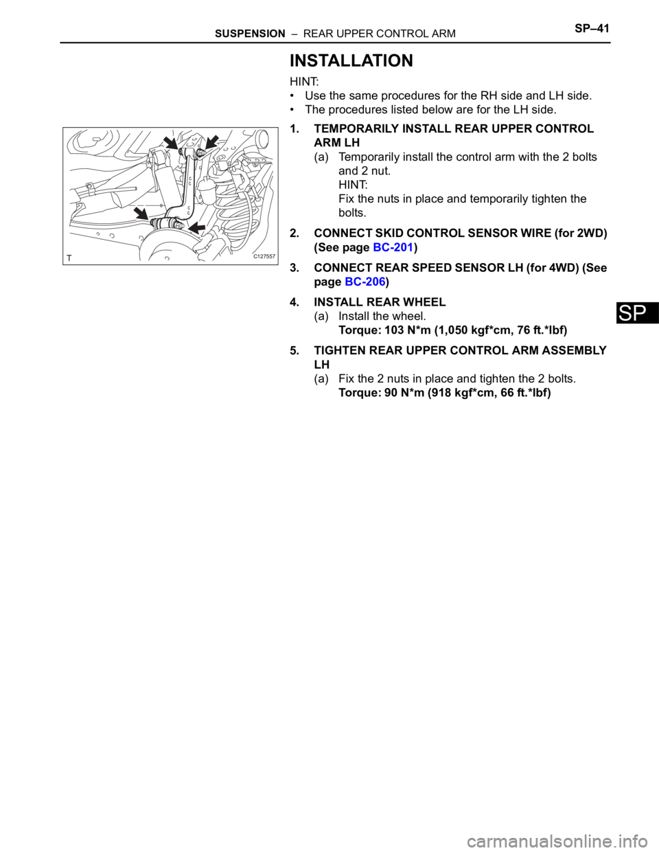
(a) Temporarily install the control arm with the 2 bolts
and 2 nut.
HINT:
Fix the nuts in place and temporarily tighten the
bolts.
2. CONNECT SKID CONTROL SENSOR WIRE (for 2WD)
(See page BC-201)
3. CONNECT REAR SPEED SENSOR LH (for 4WD) (See
page BC-206)
4. INSTALL REAR WHEEL
(a) Install the wheel.
Torque: 103 N*m (1,050 kgf*cm, 76 ft.*lbf)
5. TIGHTEN REAR UPPER CONTROL ARM ASSEMBLY
LH
(a) Fix the 2 nuts in place and tighten the 2 bolts.
Torque: 90 N*m (918 kgf*cm, 66 ft.*lbf)
C127557
Page 1472 of 2000
SUSPENSION – REAR NO. 1 SUSPENSION ARMSP–43
SP
INSTALLATION
HINT:
• Use the same procedures for the RH side and LH side.
• The procedures listed below are for the LH side.
1. TEMPORARILY TIGHTEN REAR NO. 1 SUSPENSION
ARM ASSEMBLY LH
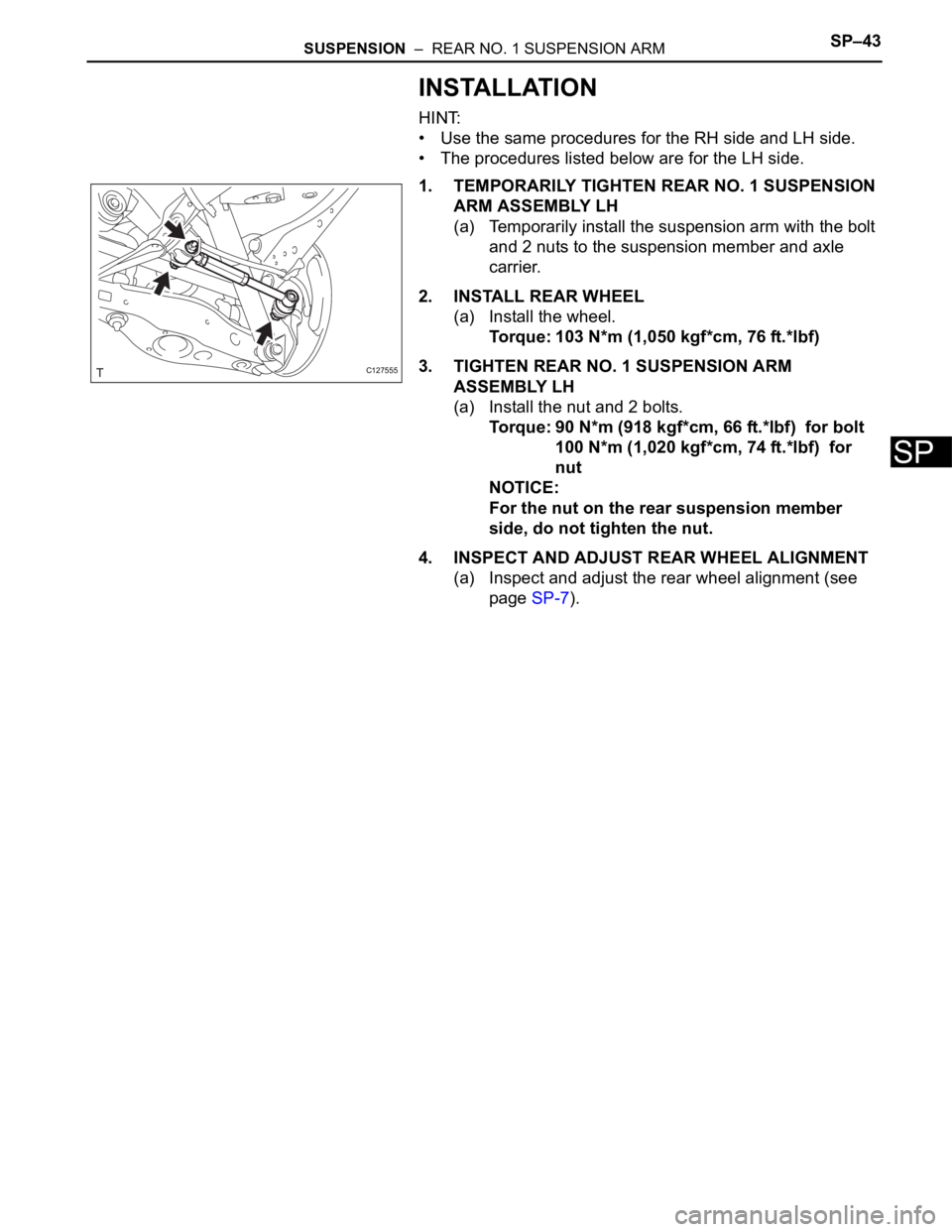
(a) Temporarily install the suspension arm with the bolt
and 2 nuts to the suspension member and axle
carrier.
2. INSTALL REAR WHEEL
(a) Install the wheel.
Torque: 103 N*m (1,050 kgf*cm, 76 ft.*lbf)
3. TIGHTEN REAR NO. 1 SUSPENSION ARM
ASSEMBLY LH
(a) Install the nut and 2 bolts.
Torque: 90 N*m (918 kgf*cm, 66 ft.*lbf) for bolt
100 N*m (1,020 kgf*cm, 74 ft.*lbf) for
nut
NOTICE:
For the nut on the rear suspension member
side, do not tighten the nut.
4. INSPECT AND ADJUST REAR WHEEL ALIGNMENT
(a) Inspect and adjust the rear wheel alignment (see
page SP-7).
C127555
Page 1473 of 2000
SUSPENSION – REAR NO. 2 SUSPENSION ARMSP–47
SP
INSTALLATION
HINT:
• Use the same procedures for the RH side and LH side.
• The procedures listed below are for the LH side.
1. TEMPORARILY INSTALL REAR NO. 2 SUSPENSION
ARM ASSEMBLY LH
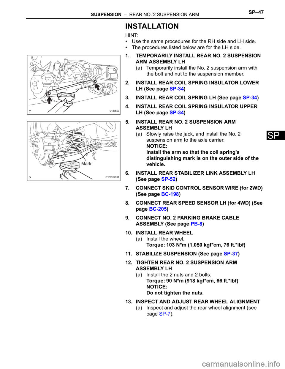
(a) Temporarily install the No. 2 suspension arm with
the bolt and nut to the suspension member.
2. INSTALL REAR COIL SPRING INSULATOR LOWER
LH (See page SP-34)
3. INSTALL REAR COIL SPRING LH (See page SP-34)
4. INSTALL REAR COIL SPRING INSULATOR UPPER
LH (See page SP-34)
5. INSTALL REAR NO. 2 SUSPENSION ARM
ASSEMBLY LH
(a) Slowly raise the jack, and install the No. 2
suspension arm to the axle carrier.
NOTICE:
Install the arm so that the coil spring's
distinguishing mark is on the outer side of the
vehicle.
6. INSTALL REAR STABILIZER LINK ASSEMBLY LH
(See page SP-52)
7. CONNECT SKID CONTROL SENSOR WIRE (for 2WD)
(See page BC-198)
8. CONNECT REAR SPEED SENSOR LH (for 4WD) (See
page BC-205)
9. CONNECT NO. 2 PARKING BRAKE CABLE
ASSEMBLY (See page PB-8)
10. INSTALL REAR WHEEL
(a) Install the wheel.
Torque: 103 N*m (1,050 kgf*cm, 76 ft.*lbf)
11. STABILIZE SUSPENSION (See page SP-37)
12. TIGHTEN REAR NO. 2 SUSPENSION ARM
ASSEMBLY LH
(a) Install the 2 nuts and 2 bolts.
Torque: 90 N*m (918 kgf*cm, 66 ft.*lbf)
NOTICE:
Do not tighten the nuts.
13. INSPECT AND ADJUST REAR WHEEL ALIGNMENT
(a) Inspect and adjust the rear wheel alignment (see
page SP-7).
C127559
C129676E01
Page 1474 of 2000
SUSPENSION – REAR TRAILING ARMSP–49
SP
INSTALLATION
HINT:
• Use the same procedures for the RH side and LH side.
• The procedures listed below are for the LH side.
1. TEMPORARILY TIGHTEN REAR TRAILING ARM
ASSEMBLY LH
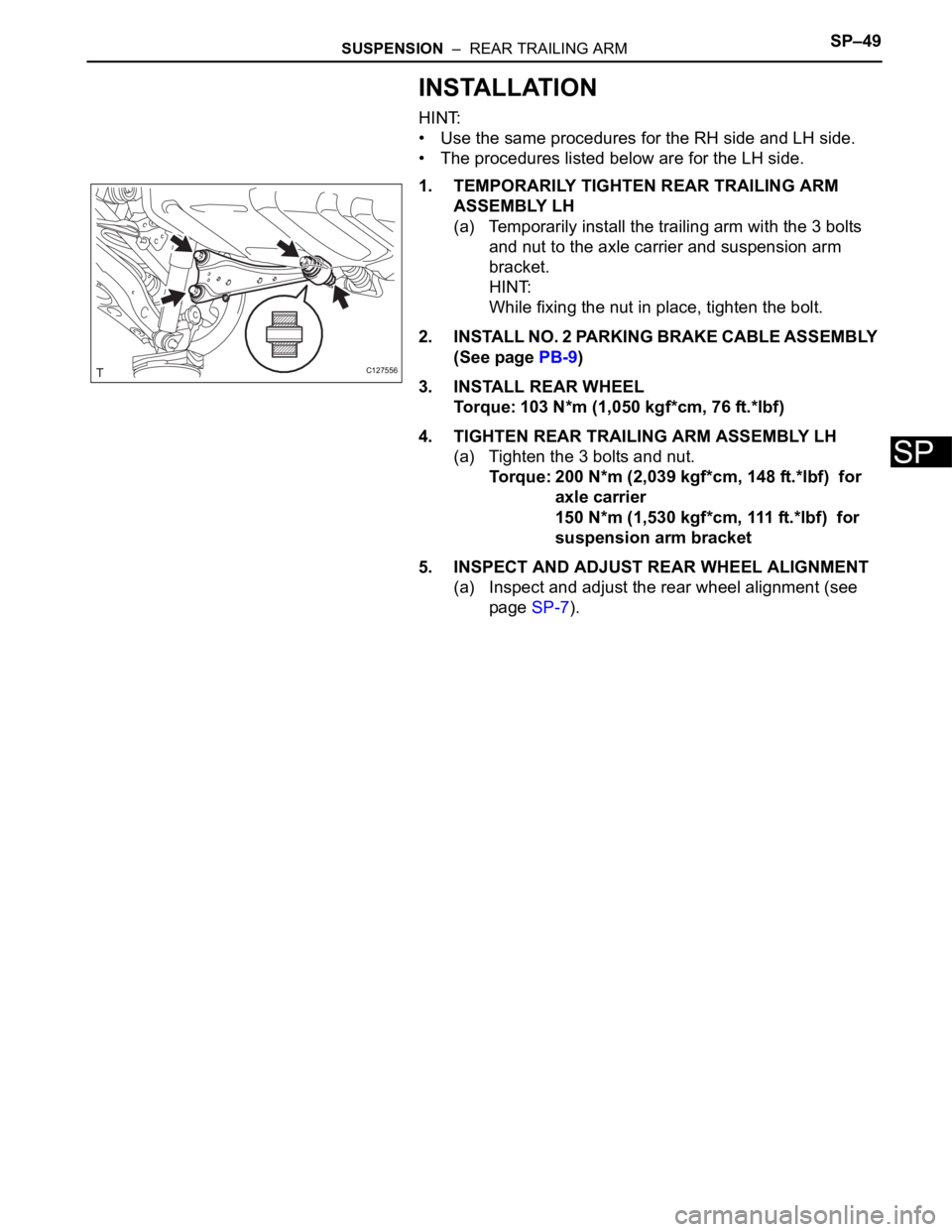
(a) Temporarily install the trailing arm with the 3 bolts
and nut to the axle carrier and suspension arm
bracket.
HINT:
While fixing the nut in place, tighten the bolt.
2. INSTALL NO. 2 PARKING BRAKE CABLE ASSEMBLY
(See page PB-9)
3. INSTALL REAR WHEEL
Torque: 103 N*m (1,050 kgf*cm, 76 ft.*lbf)
4. TIGHTEN REAR TRAILING ARM ASSEMBLY LH
(a) Tighten the 3 bolts and nut.
Torque: 200 N*m (2,039 kgf*cm, 148 ft.*lbf) for
axle carrier
150 N*m (1,530 kgf*cm, 111 ft.*lbf) for
suspension arm bracket
5. INSPECT AND ADJUST REAR WHEEL ALIGNMENT
(a) Inspect and adjust the rear wheel alignment (see
page SP-7).
C127556
Page 1475 of 2000
SUSPENSION – REAR STABILIZER BARSP–51
SP
INSPECTION
1. INSPECT REAR STABILIZER LINK ASSEMBLY LH
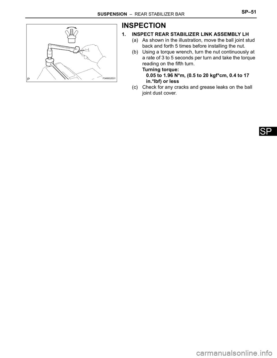
(a) As shown in the illustration, move the ball joint stud
back and forth 5 times before installing the nut.
(b) Using a torque wrench, turn the nut continuously at
a rate of 3 to 5 seconds per turn and take the torque
reading on the fifth turn.
Turning torque:
0.05 to 1.96 N*m, (0.5 to 20 kgf*cm, 0.4 to 17
in.*lbf) or less
(c) Check for any cracks and grease leaks on the ball
joint dust cover.
F049932E01
Page 1476 of 2000
SP–52SUSPENSION – REAR STABILIZER BAR
SP
INSTALLATION
HINT:
• Use the same procedures for the RH side and LH side.
• The procedures listed below are for the LH side.
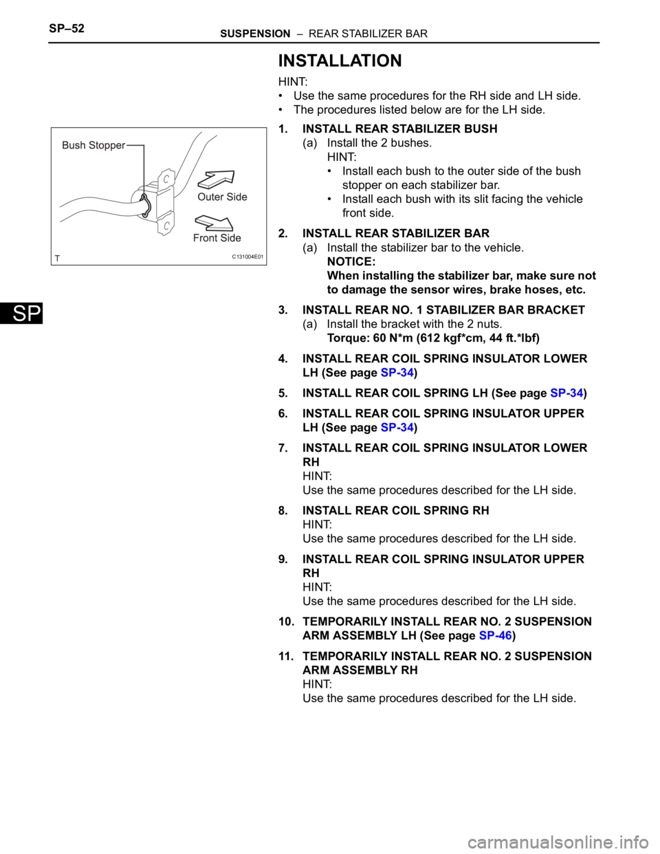
1. INSTALL REAR STABILIZER BUSH
(a) Install the 2 bushes.
HINT:
• Install each bush to the outer side of the bush
stopper on each stabilizer bar.
• Install each bush with its slit facing the vehicle
front side.
2. INSTALL REAR STABILIZER BAR
(a) Install the stabilizer bar to the vehicle.
NOTICE:
When installing the stabilizer bar, make sure not
to damage the sensor wires, brake hoses, etc.
3. INSTALL REAR NO. 1 STABILIZER BAR BRACKET
(a) Install the bracket with the 2 nuts.
Torque: 60 N*m (612 kgf*cm, 44 ft.*lbf)
4. INSTALL REAR COIL SPRING INSULATOR LOWER
LH (See page SP-34)
5. INSTALL REAR COIL SPRING LH (See page SP-34)
6. INSTALL REAR COIL SPRING INSULATOR UPPER
LH (See page SP-34)
7. INSTALL REAR COIL SPRING INSULATOR LOWER
RH
HINT:
Use the same procedures described for the LH side.
8. INSTALL REAR COIL SPRING RH
HINT:
Use the same procedures described for the LH side.
9. INSTALL REAR COIL SPRING INSULATOR UPPER
RH
HINT:
Use the same procedures described for the LH side.
10. TEMPORARILY INSTALL REAR NO. 2 SUSPENSION
ARM ASSEMBLY LH (See page SP-46)
11. TEMPORARILY INSTALL REAR NO. 2 SUSPENSION
ARM ASSEMBLY RH
HINT:
Use the same procedures described for the LH side.
C131004E01
Page 1477 of 2000
SUSPENSION – REAR STABILIZER BARSP–53
SP
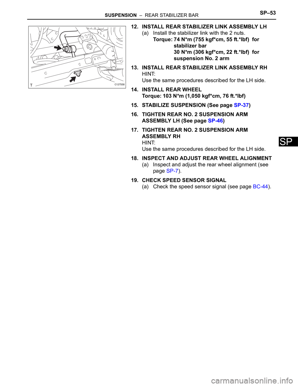
12. INSTALL REAR STABILIZER LINK ASSEMBLY LH
(a) Install the stabilizer link with the 2 nuts.
Torque: 74 N*m (755 kgf*cm, 55 ft.*lbf) for
stabilizer bar
30 N*m (306 kgf*cm, 22 ft.*lbf) for
suspension No. 2 arm
13. INSTALL REAR STABILIZER LINK ASSEMBLY RH
HINT:
Use the same procedures described for the LH side.
14. INSTALL REAR WHEEL
Torque: 103 N*m (1,050 kgf*cm, 76 ft.*lbf)
15. STABILIZE SUSPENSION (See page SP-37)
16. TIGHTEN REAR NO. 2 SUSPENSION ARM
ASSEMBLY LH (See page SP-46)
17. TIGHTEN REAR NO. 2 SUSPENSION ARM
ASSEMBLY RH
HINT:
Use the same procedures described for the LH side.
18. INSPECT AND ADJUST REAR WHEEL ALIGNMENT
(a) Inspect and adjust the rear wheel alignment (see
page SP-7).
19. CHECK SPEED SENSOR SIGNAL
(a) Check the speed sensor signal (see page BC-44).
C127558
Page 1478 of 2000
TW–6TIRE AND WHEEL – TIRE PRESSURE WARNING SYSTEM
TW
SYSTEM DESCRIPTION
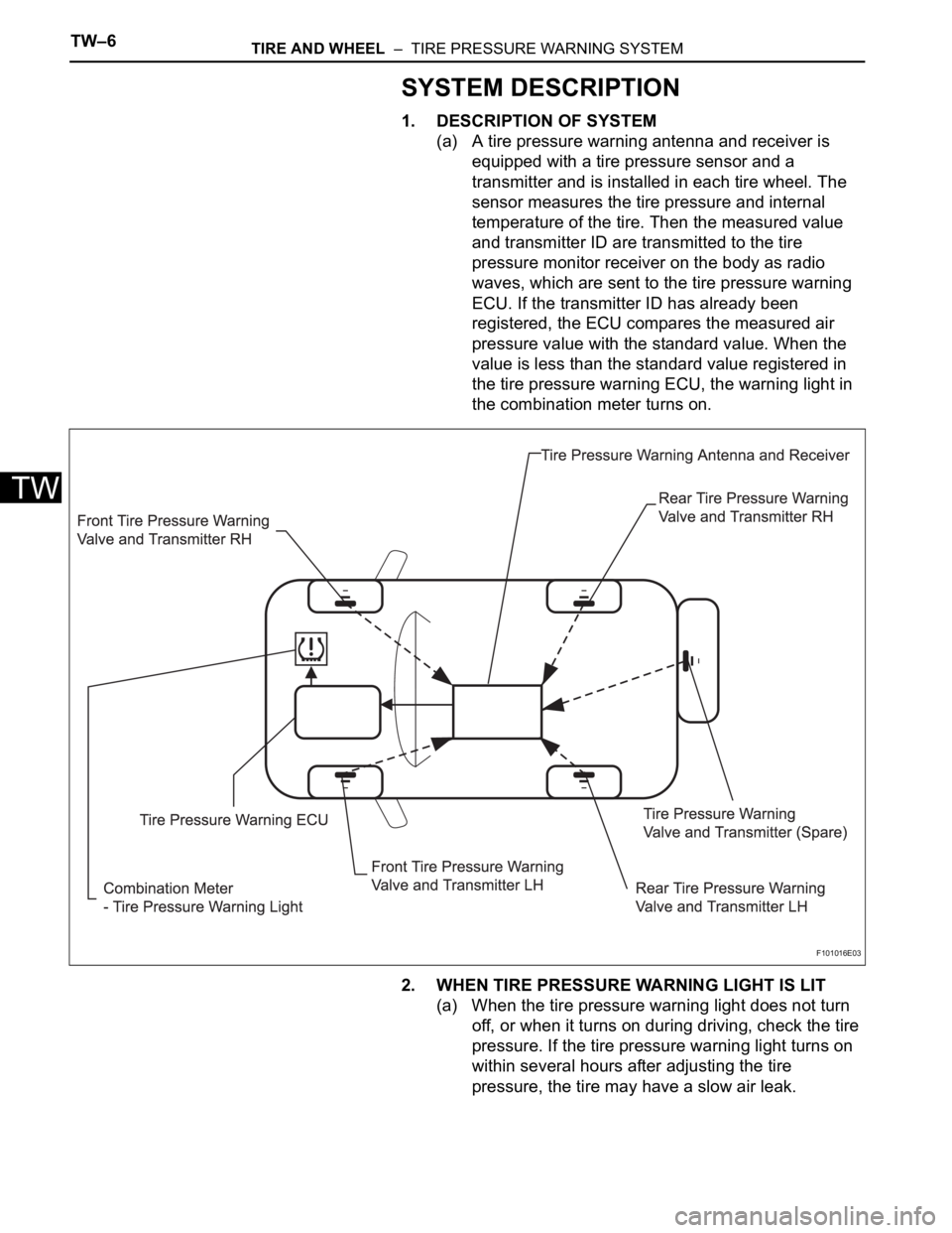
1. DESCRIPTION OF SYSTEM
(a) A tire pressure warning antenna and receiver is
equipped with a tire pressure sensor and a
transmitter and is installed in each tire wheel. The
sensor measures the tire pressure and internal
temperature of the tire. Then the measured value
and transmitter ID are transmitted to the tire
pressure monitor receiver on the body as radio
waves, which are sent to the tire pressure warning
ECU. If the transmitter ID has already been
registered, the ECU compares the measured air
pressure value with the standard value. When the
value is less than the standard value registered in
the tire pressure warning ECU, the warning light in
the combination meter turns on.
2. WHEN TIRE PRESSURE WARNING LIGHT IS LIT
(a) When the tire pressure warning light does not turn
off, or when it turns on during driving, check the tire
pressure. If the tire pressure warning light turns on
within several hours after adjusting the tire
pressure, the tire may have a slow air leak.
F101016E03
Page 1479 of 2000

TIRE AND WHEEL – TIRE PRESSURE WARNING SYSTEMTW–7
TW
(b) Under the following conditions, the system may not
function properly;
• Areas, facilities or devices that use similar radio
frequencies are located in the vicinity of the
vehicle.
• Devices using similar radio frequencies are used
in the vehicle.
• Large amounts of snow or ice are stuck to the
vehicle, especially on the wheels and around the
wheel houses.
• The battery of the transmitter is depleted.
• Tires and wheels without tire pressure warning
valves and transmitters are used.
• Snow tires and tire chains are used.
• If wheels other than the specified ones are used,
the system may not function properly because
different radio waves are transmitted from the tire
pressure warning valve and transmitter.
• Depending on the tire type, the tire pressure
warning valve and transmitter may not function
properly even though the specified wheels are
used.
• The system may not function properly if it is
initialized with tire pressures which are not the
specified values.
(c) The average life of the grommet of the tire pressure
warning antenna and receiver is approximately 5
years, at which time it must be replaced. Retighten
the valve nut if the valve is leaking air, if it is less
than 5 years old, and there is no problem with the
grommets.
(d) After removing and installing the ECU or a sensor,
output a diagnosis code and check that it is a
normal code.
3. FUNCTION OF COMPONENTS
Components Function
Tire pressure warning antenna and receiver • Combined as a single unit with a disc wheel air valve, it measures
tire pressure and temperature, and transmits an ID number for
measurement value and identification
• Battery is built into valve
Tire pressure warning antenna and receiver Receives necessary signals from tire pressure warning antenna and
receiver and transmits them to tire pressure warning ECU
Tire pressure warning ECU • Receives signal from receiver and identifies it as vehicle's own
signal.
• If measurement value is equal to or lower than specified value, it
transmits a signal so that the air pressure warning light on
combination meter turns on.
Tire pressure warning light Located in the combination meter, it informs driver of lowered tire air
pressure and system failure
Page 1480 of 2000
TW–8TIRE AND WHEEL – TIRE PRESSURE WARNING SYSTEM
TW
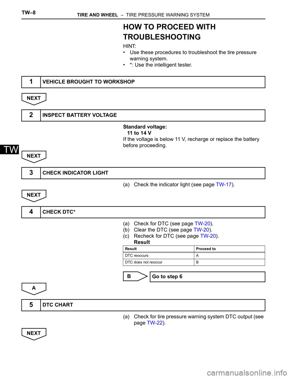
HOW TO PROCEED WITH
TROUBLESHOOTING
HINT:
• Use these procedures to troubleshoot the tire pressure
warning system.
• *: Use the intelligent tester.
NEXT
Standard voltage:
11 to 14 V
If the voltage is below 11 V, recharge or replace the battery
before proceeding.
NEXT
(a) Check the indicator light (see page TW-17).
NEXT
(a) Check for DTC (see page TW-20).
(b) Clear the DTC (see page TW-20).
(c) Recheck for DTC (see page TW-20).
Result
B
A
(a) Check for tire pressure warning system DTC output (see
page TW-22).
NEXT
1VEHICLE BROUGHT TO WORKSHOP
2INSPECT BATTERY VOLTAGE
3CHECK INDICATOR LIGHT
4CHECK DTC*
Result Proceed to
DTC reoccurs A
DTC does not reoccur B
Go to step 6
5DTC CHART