TOYOTA RAV4 2006 Service Repair Manual
Manufacturer: TOYOTA, Model Year: 2006, Model line: RAV4, Model: TOYOTA RAV4 2006Pages: 2000, PDF Size: 45.84 MB
Page 1851 of 2000
LI–20LIGHTING – LIGHTING SYSTEM
LI
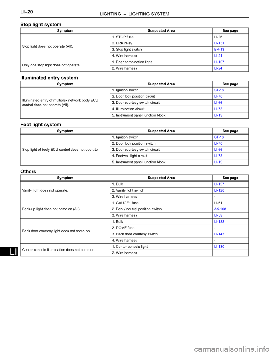
Stop light system
Illuminated entry system
Foot light system
Others
Symptom Suspected Area See page
Stop light does not operate (All).1. STOP fuse LI-26
2. BRK relayLI-151
3. Stop light switchBR-13
4. Wire harnessLI-24
Only one stop light does not operate.1. Rear combination lightLI-107
2. Wire harnessLI-24
Symptom Suspected Area See page
Illuminated entry of multiplex network body ECU
control does not operate (All).1. Ignition switchST-18
2. Door lock position circuitLI-70
3. Door courtesy switch circuitLI-66
4. Illumination circuitLI-75
5. Instrument panel junction blockLI-19
Symptom Suspected Area See page
Step light of body ECU control does not operate.1. Ignition switchST-18
2. Door lock position switchLI-70
3. Door courtesy switch circuitLI-66
4. Footwell light circuitLI-73
5. Instrument panel junction blockLI-19
Symptom Suspected Area See page
Vanity light does not operate.1. BulbLI-127
2. Vanity light switchLI-128
3. Wire harness -
Back-up light does not come on (All).1. GAUGE1 fuse LI-61
2. Park / neutral position switchAX-108
3. Wire harnessLI-59
Back door courtesy light does not come on.1. BulbLI-122
2. DOME fuse -
3. Back door courtesy switchLI-143
4. Wire harness -
Center console illumination does not come on.1. Center console lightLI-130
2. Wire harness -
Page 1852 of 2000
LIGHTING – LIGHTING SYSTEMLI–21
LI
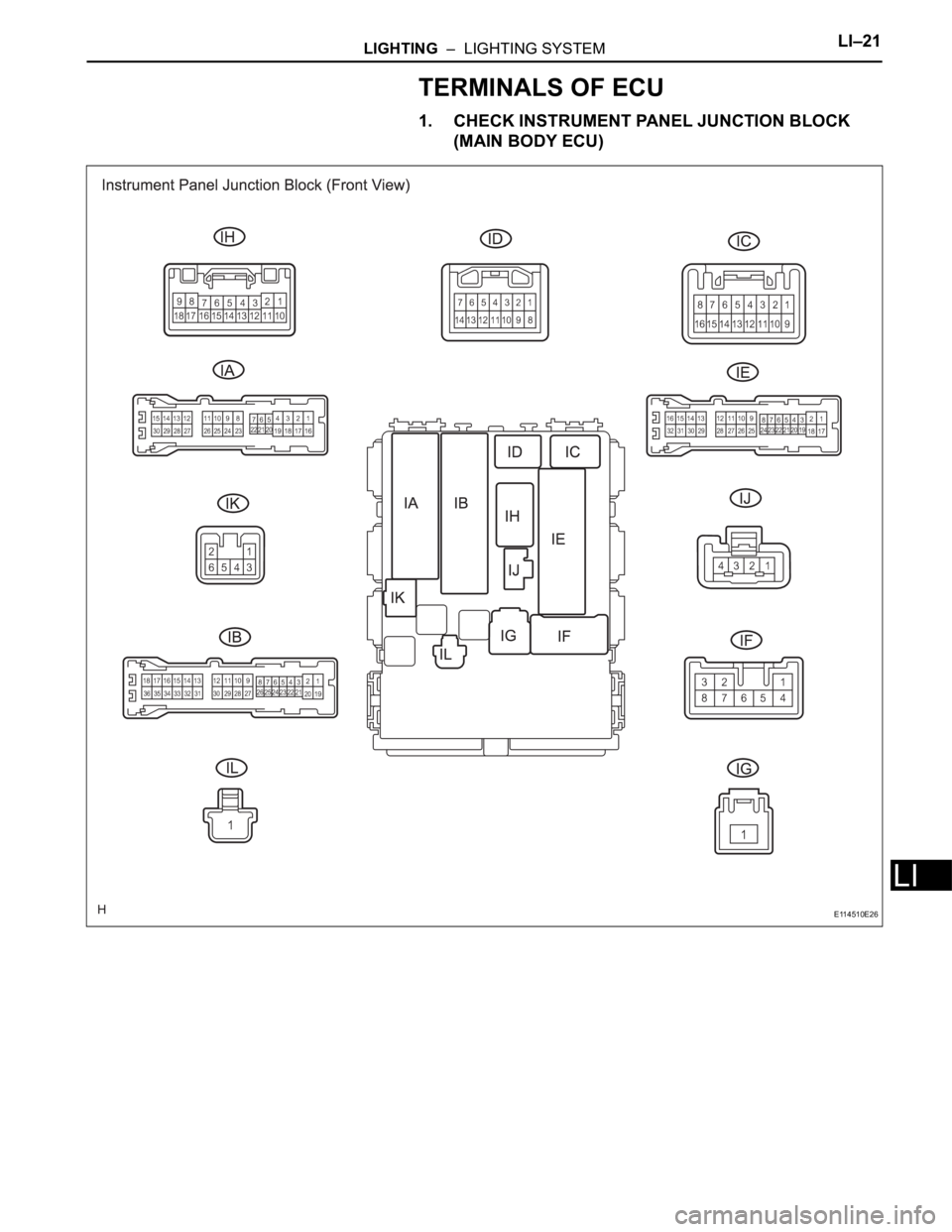
TERMINALS OF ECU
1. CHECK INSTRUMENT PANEL JUNCTION BLOCK
(MAIN BODY ECU)
E114510E26
Page 1853 of 2000
LI–22LIGHTING – LIGHTING SYSTEM
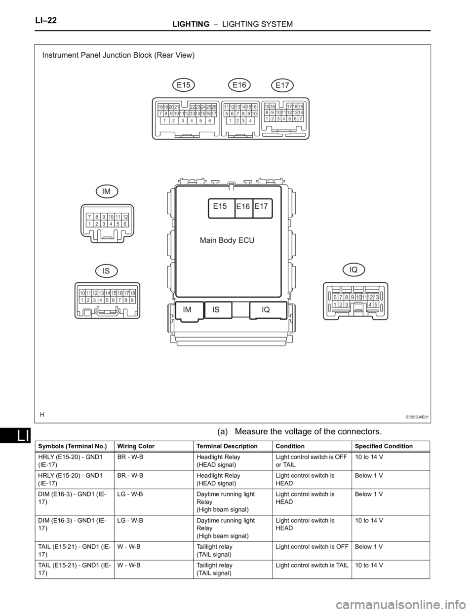
LI(a) Measure the voltage of the connectors.
E125304E01
Symbols (Terminal No.) Wiring Color Terminal Description ConditionSpecified Condition
HRLY (E15-20) - GND1
(IE-17)BR - W-B Headlight Relay
(HEAD signal)Light control switch is OFF
or TAIL10 to 14 V
HRLY (E15-20) - GND1
(IE-17)BR - W-B Headlight Relay
(HEAD signal)Light control switch is
HEADBelow 1 V
DIM (E16-3) - GND1 (IE-
17)LG - W-B Daytime running light
Relay
(High beam signal)Light control switch is
HEADBelow 1 V
DIM (E16-3) - GND1 (IE-
17)LG - W-B Daytime running light
Relay
(High beam signal)Light control switch is
HEAD10 to 14 V
TAIL (E15-21) - GND1 (IE-
17)W - W-B Taillight relay
(TAIL signal)Light control switch is OFF Below 1 V
TAIL (E15-21) - GND1 (IE-
17)W - W-B Taillight relay
(TAIL signal)Light control switch is TAIL 10 to 14 V
Page 1854 of 2000

LIGHTING – LIGHTING SYSTEMLI–23
LI
ILE (IK-2) - GND1 (IE-17) W - W-B Illumination signal • Room light switch
position is DOOR
•Door closed10 to 14 V
ILE (IK-2) - GND1 (IE-17) W - W-B Illumination signal • Room light switch
position is DOOR
• Door openBelow 1 V
FSPT (E15-2) - GND1 (IE-
17)V - W-B Foot light illumination
(Illumination signal)Foot light illumination OFF 10 to 14 V
FSPT (E15-2) - GND1 (IE-
17)V - W-B Foot light illumination
(Illumination signal)Foot light illumination ON Below 1 V
HU (IJ-4) - GND1 (IE-17) O - W-B Headlight dimmer switch
(HIGH signal)Light control switch is
HEAD
Headlight dimmer switch
is LOW10 to 14 V
HU (IJ-4) - GND1 (IE-17) O - W-B Headlight dimmer switch
(HIGH signal)Light control switch is
HEAD
Headlight dimmer switch
is HIGHBelow 1 V
LCTY (E15-8) - GND1 (IE-
17)SB - W-B Courtesy switch
(Rear left door circuit)Rear left door is closed Below 1 V
LCTY (E15-8) - GND1 (IE-
17)SB - W-B Courtesy switch
(Rear left door circuit)Rear left door is open 10 to 14 V
FFGO (E17-17) - GND1
(IE-17)G - W-B Front fog relay
(Front fog circuit)Front fog light is OFF 10 to 14 V
FFGO (E17-17) - GND1
(IE-17)G - W-B Front fog relay
(Front fog circuit)Front fog light is ON Below 1 V
DCTY (IA-21) - GND1 (IE-
17)W - W-B Courtesy switch
(Front left door circuit)Front left door is open Below 1 V
DCTY (IA-21) - GND1 (IE-
17)W - W-B Courtesy switch
(Front left door circuit)Front left door is closed 10 to 14 V
RRCY (ID-7) - GND1 (IE-
17)LG - W-B Courtesy switch
(Rear right door circuit)Rear right door is open Below 1 V
RRCY (ID-7) - GND1 (IE-
17)LG - W-B Courtesy switch
(Rear right door circuit)Rear right door is closed 10 to 14 V
HF (E15-22) - GND1 (IE-
17)R - W-B Headlight dimmer switch
(FLASH signal)Headlight dimmer switch
is OFF10 to 14 V
HF (E15-22) - GND1 (IE-
17)R - W-B Headlight dimmer switch
(FLASH signal)Headlight dimmer switch
is FLASHBelow 1 V
FFOG (E17-13) - GND1
(IE-17)GR - W-B Front fog light switch
(Front fog light signal)Light control switch is TAIL
Fog light switch is OFF10 to 14 V
FFOG (E17-13) - GND1
(IE-17)GR - W-B Front fog light switch
(Front fog light signal)Light control switch is TAIL
Fog light switch is ONBelow 1 V
PCTY (IC-14) - GND1 (IE-
17)BR - W-B Courtesy switch
(Front right door circuit)Front right door is open Below 1 V
PCTY (IC-14) - GND1 (IE-
17)BR - W-B Courtesy switch
(Front right door circuit)Front right door is closed 10 to 14 V
BCTY (IA-7) - GND1 (IE-
17)LG - W-B Courtesy switch
(Back door)Back door is open Below 1 V
BCTY (IA-7) - GND1 (IE-
17)LG - W-B Courtesy switch
(Back door)Back door is closed 10 to 14 V
LSWP (E15-10) - GND1
(IE-17)Y - W-B Door lock position switch
(Front right door)Front right door is in
unlock position10 to 14 V
LSWP (E15-10) - GND1
(IE-17)Y - W-B Door lock position switch
(Front right door)Front right door is in lock
positionBelow 1 V
LSWD (E15-25) - GND1
(IE-17)Y - W-B Door lock position switch
(Front left door)Front left door is in unlock
position10 to 14 V
LSWD (E15-25) - GND1
(IE-17)Y - W-B Door lock position switch
(Front left door)Front left door is in lock
positionBelow 1 V Symbols (Terminal No.) Wiring Color Terminal Description ConditionSpecified Condition
Page 1855 of 2000
LI–24LIGHTING – LIGHTING SYSTEM
LI
If the result is not as specified, the junction block
(main body ECU) may have a malfunction.
DATA LIST / ACTIVE TEST
1. READ DATA LIST
HINT:
Using the intelligent tester's DATA LIST allows switch,
sensor, actuator and other item values to be read without
removing any parts. Reading the DATA LIST early in
troubleshooting is one way to save time.
(a) Connect the intelligent tester (with CAN VIM) to the
DLC3.
(b) Turn the ignition switch ON.
(c) Read the DATA LIST according to the display on the
tester.
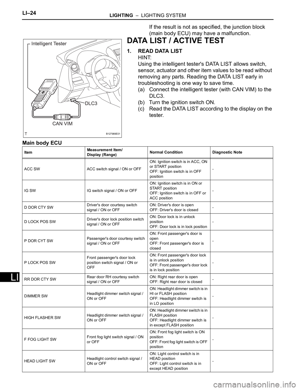
Main body ECU
B127989E01
ItemMeasurement Item/
Display (Range)Normal Condition Diagnostic Note
ACC SW ACC switch signal / ON or OFFON: Ignition switch is in ACC, ON
or START position
OFF: Ignition switch is in OFF
position-
IG SW IG switch signal / ON or OFFON: Ignition switch is in ON or
START position
OFF: Ignition switch is in OFF or
ACC position-
D DOR CTY SWDriver's door courtesy switch
signal / ON or OFFON: Driver's door is open
OFF: Driver's door is closed-
D LOCK POS SWDriver's door lock position switch
signal / ON or OFFON: Door lock is in unlock
position
OFF: Door lock is in lock position-
P DOR CYT SWPassenger's door courtesy switch
signal / ON or OFFON: Front passenger's door is
open
OFF: Front passenger's door is
closed-
P LOCK POS SWFront passenger's door lock
position switch signal / ON or
OFFON: Front passenger's door lock
is in unlock position
OFF: Front passenger's door lock
is in lock position-
RR DOR CTY SWRear door RH courtesy switch
signal / ON or OFFON: Right rear door is open
OFF: Right rear door is closed-
DIMMER SWHeadlight dimmer switch signal /
ON or OFFON: Headlight dimmer switch is in
HI or FLASH position
OFF: Headlight dimmer switch is
in LO position-
HIGH FLASHER SWHeadlight dimmer switch signal /
ON or OFFON: Headlight dimmer switch is in
FLASH position
OFF: Headlight dimmer switch is
in except FLASH position-
F FOG LIGHT SWFront fog light switch signal / ON
or OFFON: Front fog light switch is ON
position
OF F: F ron t fog light switch is OFF
position-
HEAD LIGHT SWHeadlight control switch signal /
ON or OFFON: Light control switch is in
HEAD position
OFF: Light control switch is in
except HEAD position-
Page 1856 of 2000

LIGHTING – LIGHTING SYSTEMLI–25
LI
2. PERFORM ACTIVE TEST
HINT:
Performing the intelligent tester's ACTIVE TEST allows
relay, VSV, actuator and other items to be operated
without removing any parts. Performing the ACTIVE
TEST early in troubleshooting is one way to save time.
The DATA LIST can be displayed during the ACTIVE
TEST.
(a) Connect the intelligent tester (with CAN VIM) to the
DLC3.
(b) Turn the ignition switch ON.
(c) Perform the ACTIVE TEST by following the
directions on the tester screen.
Main body ECU
TAIL LIGHT SW Taillight switch signal / ON or OFFON: Light control switch is in TAIL
or HEAD position
OFF: Light control switch is in
OFF position-
RL DOR CTY SWRear door LH courtesy switch
signal / ON or OFFON: Left rear door is open
OFF Left rear door is closed-
BK DOR CTY SWBack door courtesy switch signal /
ON or OFFON: Back door is open
OFF: Back door is closed- ItemMeasurement Item/
Display (Range)Normal Condition Diagnostic Note
Item Test Details Diagnostic Note
HAZARD Turn hazard light flasher relay ON / OFF -
F FOG LIGHT RLY Turn front fog light relay ON / OFF -
HEAD LIGHT Turn headlight relay ON / OFF -
HEAD LIGHT (HI)Turn headlight dimmer relay (Headlight
dimmer switch HI position) ON / OFF-
TAIL LIGHT Turn taillight relay ON / OFF -
ILLUMI OUTPUTTest Details:
Turn interior light and key illumination ON /
OFF
Vehicle Condition:
Interior light switch is in DOOR position and
all doors are closed-
STEP LIGHT Foot light illumination ON / OFF -
Page 1857 of 2000
LI–26LIGHTING – LIGHTING SYSTEM
LI
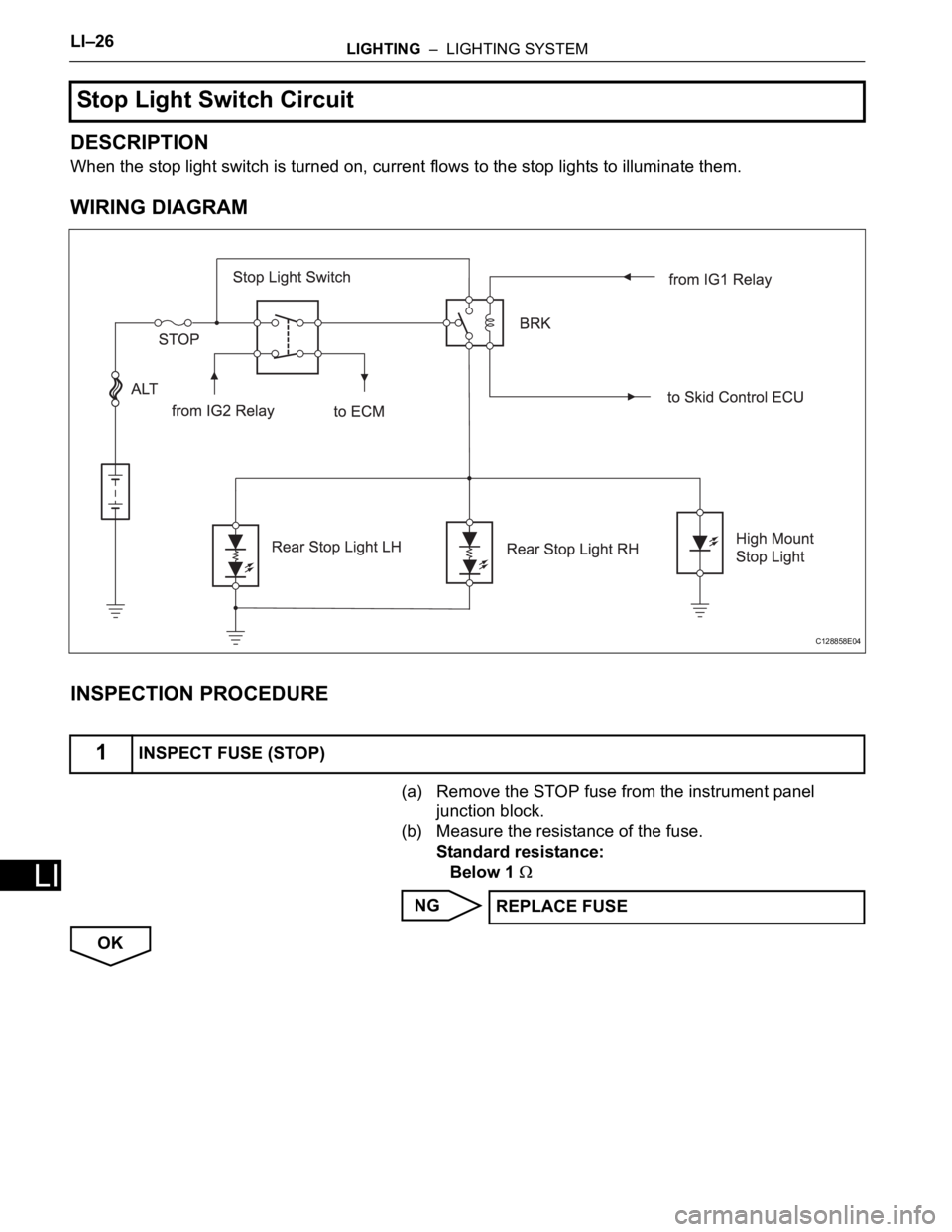
DESCRIPTION
When the stop light switch is turned on, current flows to the stop lights to illuminate them.
WIRING DIAGRAM
INSPECTION PROCEDURE
(a) Remove the STOP fuse from the instrument panel
junction block.
(b) Measure the resistance of the fuse.
Standard resistance:
Below 1
NG
OK
Stop Light Switch Circuit
1INSPECT FUSE (STOP)
C128858E04
REPLACE FUSE
Page 1858 of 2000
LIGHTING – LIGHTING SYSTEMLI–27
LI
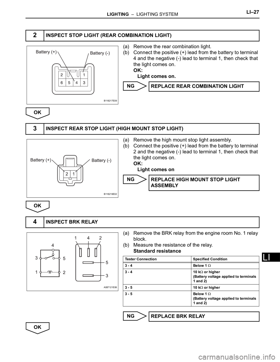
(a) Remove the rear combination light.
(b) Connect the positive (+) lead from the battery to terminal
4 and the negative (-) lead to terminal 1, then check that
the light comes on.
OK:
Light comes on.
NG
OK
(a) Remove the high mount stop light assembly.
(b) Connect the positive (+) lead from the battery to terminal
2 and the negative (-) lead to terminal 1, then check that
the light comes on.
OK:
Light comes on
NG
OK
(a) Remove the BRK relay from the engine room No. 1 relay
block.
(b) Measure the resistance of the relay.
Standard resistance
NG
OK
2INSPECT STOP LIGHT (REAR COMBINATION LIGHT)
B118217E09
REPLACE REAR COMBINATION LIGHT
3INSPECT REAR STOP LIGHT (HIGH MOUNT STOP LIGHT)
B118219E02
REPLACE HIGH MOUNT STOP LIGHT
ASSEMBLY
4INSPECT BRK RELAY
A087121E06
Tester Connection Specified Condition
3 - 4 Below 1
3 - 4 10 k or higher
(Battery voltage applied to terminals
1 and 2)
3 - 5 10 k
or higher
3 - 5 Below 1
(Battery voltage applied to terminals
1 and 2)
REPLACE BRK RELAY
Page 1859 of 2000
LI–28LIGHTING – LIGHTING SYSTEM
LI
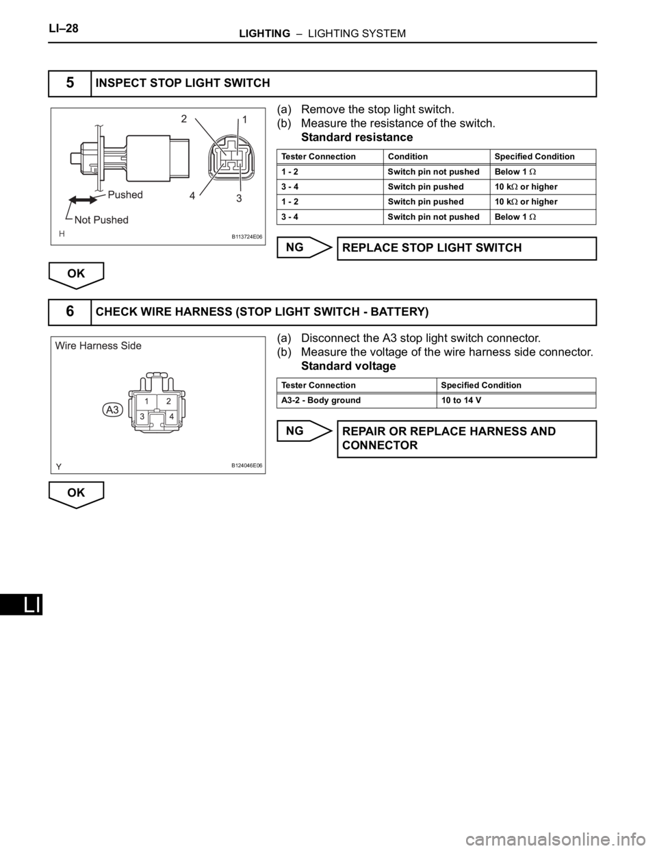
(a) Remove the stop light switch.
(b) Measure the resistance of the switch.
Standard resistance
NG
OK
(a) Disconnect the A3 stop light switch connector.
(b) Measure the voltage of the wire harness side connector.
Standard voltage
NG
OK
5INSPECT STOP LIGHT SWITCH
B113724E06
Tester Connection Condition Specified Condition
1 - 2 Switch pin not pushed Below 1
3 - 4 Switch pin pushed 10 k or higher
1 - 2 Switch pin pushed 10 k
or higher
3 - 4 Switch pin not pushed Below 1
REPLACE STOP LIGHT SWITCH
6CHECK WIRE HARNESS (STOP LIGHT SWITCH - BATTERY)
B124046E06
Tester Connection Specified Condition
A3-2 - Body ground 10 to 14 V
REPAIR OR REPLACE HARNESS AND
CONNECTOR
Page 1860 of 2000
LIGHTING – LIGHTING SYSTEMLI–29
LI
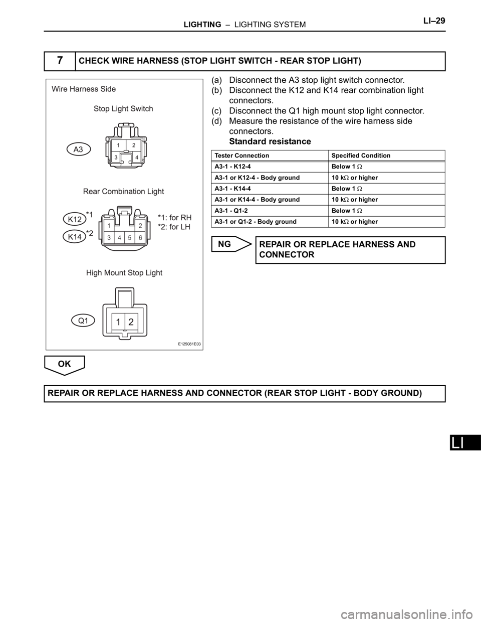
(a) Disconnect the A3 stop light switch connector.
(b) Disconnect the K12 and K14 rear combination light
connectors.
(c) Disconnect the Q1 high mount stop light connector.
(d) Measure the resistance of the wire harness side
connectors.
Standard resistance
NG
OK
7CHECK WIRE HARNESS (STOP LIGHT SWITCH - REAR STOP LIGHT)
E125081E03
Tester Connection Specified Condition
A3-1 - K12-4 Below 1
A3-1 or K12-4 - Body ground 10 k or higher
A3-1 - K14-4 Below 1
A3-1 or K14-4 - Body ground 10 k or higher
A3-1 - Q1-2 Below 1
A3-1 or Q1-2 - Body ground 10 k or higher
REPAIR OR REPLACE HARNESS AND
CONNECTOR
REPAIR OR REPLACE HARNESS AND CONNECTOR (REAR STOP LIGHT - BODY GROUND)