TOYOTA RAV4 2006 Service Repair Manual
Manufacturer: TOYOTA, Model Year: 2006, Model line: RAV4, Model: TOYOTA RAV4 2006Pages: 2000, PDF Size: 45.84 MB
Page 1831 of 2000
CC–32CRUISE CONTROL – CRUISE CONTROL SYSTEM
CC
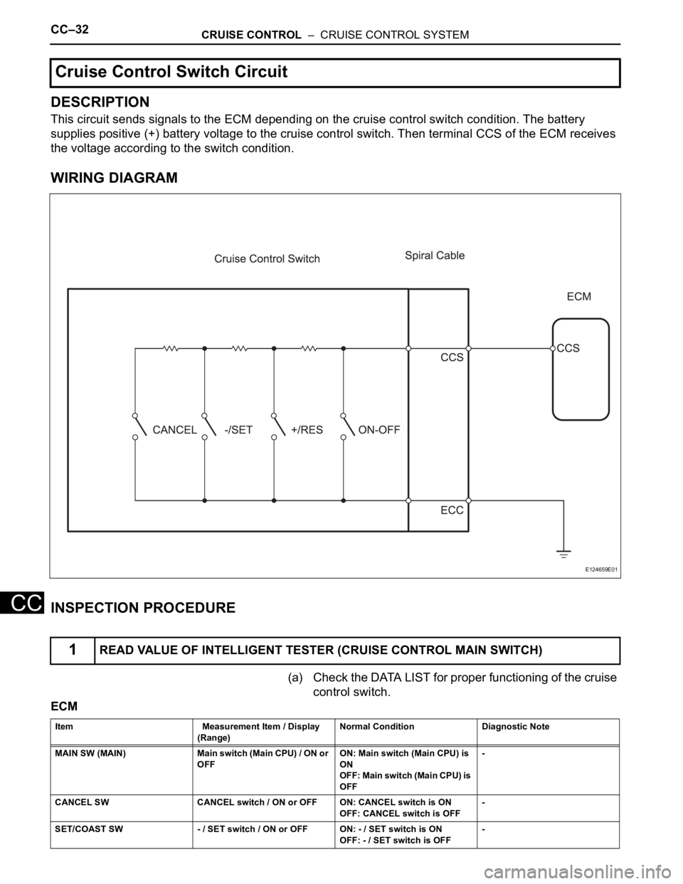
DESCRIPTION
This circuit sends signals to the ECM depending on the cruise control switch condition. The battery
supplies positive (+) battery voltage to the cruise control switch. Then terminal CCS of the ECM receives
the voltage according to the switch condition.
WIRING DIAGRAM
INSPECTION PROCEDURE
(a) Check the DATA LIST for proper functioning of the cruise
control switch.
ECM
Cruise Control Switch Circuit
1READ VALUE OF INTELLIGENT TESTER (CRUISE CONTROL MAIN SWITCH)
E124659E01
Item Measurement Item / Display
(Range) Normal Condition Diagnostic Note
MAIN SW (MAIN) Main switch (Main CPU) / ON or
OFF ON: Main switch (Main CPU) is
ON
OFF: Main switch (Main CPU) is
OFF -
CANCEL SW CANCEL switch / ON or OFF ON: CANCEL switch is ON
OFF: CANCEL switch is OFF -
SET/COAST SW - / SET switch / ON or OFF ON: - / SET switch is ON
OFF: - / SET switch is OFF -
Page 1832 of 2000
CRUISE CONTROL – CRUISE CONTROL SYSTEMCC–33
CC
OK:
When cruise control switch operation is
performed, the results will be same as above.
OK
NG
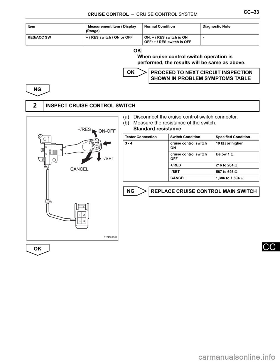
(a) Disconnect the cruise control switch connector.
(b) Measure the resistance of the switch.
Standard resistance
NG
OK
RES/ACC SW + / RES switch / ON or OFF ON: + / RES switch is ON
OFF: + / RES switch is OFF - Item Measurement Item / Display
(Range) Normal Condition Diagnostic Note
PROCEED TO NEXT CIRCUIT INSPECTION
SHOWN IN PROBLEM SYMPTOMS TABLE
2INSPECT CRUISE CONTROL SWITCH
E124663E01
Tester Connection Switch Condition Specified Condition
3 - 4 cruise control switch
ON10 k
or higher
cruise control switch
OFFBelow 1
+/RES 216 to 264
-/SET 567 to 693
CANCEL 1,386 to 1,694
REPLACE CRUISE CONTROL MAIN SWITCH
Page 1833 of 2000
CC–34CRUISE CONTROL – CRUISE CONTROL SYSTEM
CC
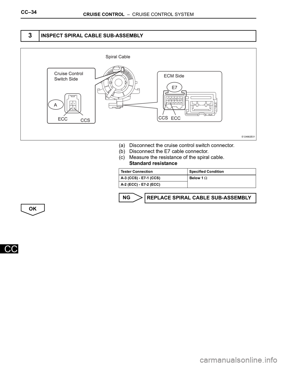
(a) Disconnect the cruise control switch connector.
(b) Disconnect the E7 cable connector.
(c) Measure the resistance of the spiral cable.
Standard resistance
NG
OK
3INSPECT SPIRAL CABLE SUB-ASSEMBLY
E124662E01
Tester Connection Specified Condition
A-3 (CCS) - E7-1 (CCS) Below 1
A-2 (ECC) - E7-2 (ECC)
REPLACE SPIRAL CABLE SUB-ASSEMBLY
Page 1834 of 2000
CRUISE CONTROL – CRUISE CONTROL SYSTEMCC–35
CC
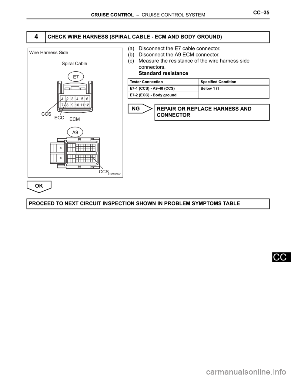
(a) Disconnect the E7 cable connector.
(b) Disconnect the A9 ECM connector.
(c) Measure the resistance of the wire harness side
connectors.
Standard resistance
NG
OK
4CHECK WIRE HARNESS (SPIRAL CABLE - ECM AND BODY GROUND)
E124664E01
Tester Connection Specified Condition
E7-1 (CCS) - A9-40 (CCS) Below 1
E7-2 (ECC) - Body ground
REPAIR OR REPLACE HARNESS AND
CONNECTOR
PROCEED TO NEXT CIRCUIT INSPECTION SHOWN IN PROBLEM SYMPTOMS TABLE
Page 1835 of 2000
CC–36CRUISE CONTROL – CRUISE CONTROL SYSTEM
CC
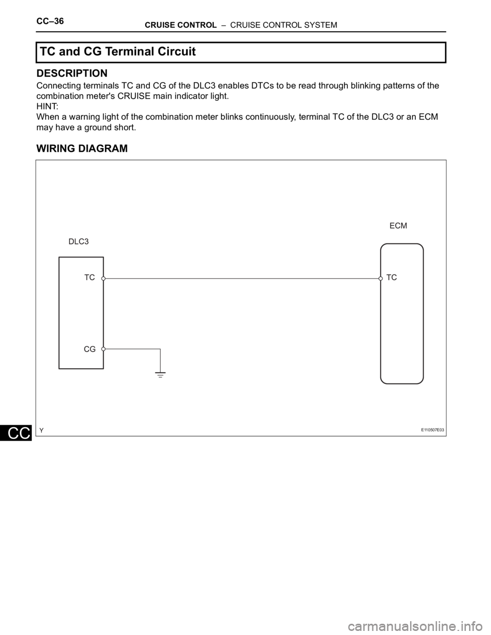
DESCRIPTION
Connecting terminals TC and CG of the DLC3 enables DTCs to be read through blinking patterns of the
combination meter's CRUISE main indicator light.
HINT:
When a warning light of the combination meter blinks continuously, terminal TC of the DLC3 or an ECM
may have a ground short.
WIRING DIAGRAM
TC and CG Terminal Circuit
E110507E03
Page 1836 of 2000
CRUISE CONTROL – CRUISE CONTROL SYSTEMCC–37
CC
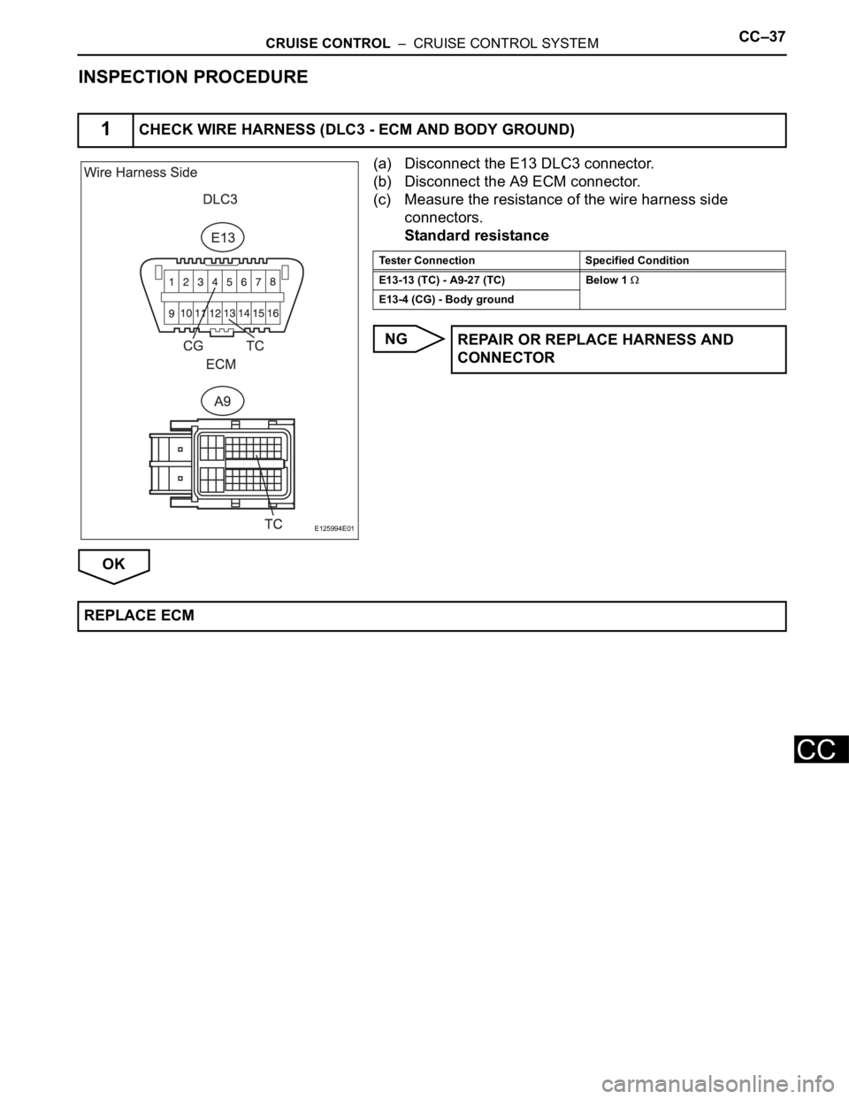
INSPECTION PROCEDURE
(a) Disconnect the E13 DLC3 connector.
(b) Disconnect the A9 ECM connector.
(c) Measure the resistance of the wire harness side
connectors.
Standard resistance
NG
OK
1CHECK WIRE HARNESS (DLC3 - ECM AND BODY GROUND)
E125994E01
Tester Connection Specified Condition
E13-13 (TC) - A9-27 (TC) Below 1
E13-4 (CG) - Body ground
REPAIR OR REPLACE HARNESS AND
CONNECTOR
REPLACE ECM
Page 1837 of 2000
CRUISE CONTROL – CRUISE CONTROL MAIN SWITCHCC–37
CC
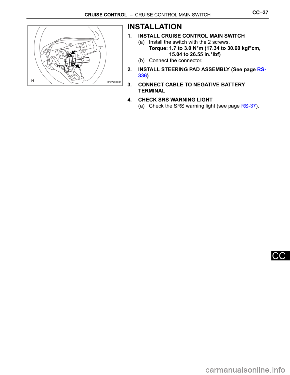
INSTALLATION
1. INSTALL CRUISE CONTROL MAIN SWITCH
(a) Install the switch with the 2 screws.
Torque: 1.7 to 3.0 N*m (17.34 to 30.60 kgf*cm,
15.04 to 26.55 in.*lbf)
(b) Connect the connector.
2. INSTALL STEERING PAD ASSEMBLY (See page RS-
336)
3. CONNECT CABLE TO NEGATIVE BATTERY
TERMINAL
4. CHECK SRS WARNING LIGHT
(a) Check the SRS warning light (see page RS-37).
B127290E08
Page 1838 of 2000

LIGHTING – LIGHTING SYSTEMLI–7
LI
SYSTEM DESCRIPTION
1. LIGHTING SYSTEM
(a) Illumination control system (Illuminated entry
system):
When the doors are unlocked by a key or
transmitter operation, or when a door is opened or
closed, the illuminated entry system turns on the
room light, map light, foot light and ignition key
cylinder light*1 or transponder key amplifier*2.
(1) The main body ECU receives the following
signals (A).
• Door courtesy switch signal
• Door detection switch signal
• Ignition switch signal
(2) The main body ECU controls the following signal
based on the signals listed in A.
• Illumination operation signal
(3) The main body ECU controls the on/off and
fade-in/fade-out operation of the following parts.
•Room light
• Map light
•Foot light
• Ignition key cylinder light*1 or transponder
key amplifier*2
HINT:
*1: w/o Engine immobiliser system
*2: w/ Engine immobiliser system
(b) Battery saver system:
When the ignition switch is turned off and any of the
doors is open continuously for 20 minutes, the main
body ECU turns the illumination operation signal off.
As a result, the room light, map light, foot light and
ignition key cylinder lights*1 or transponder key
amplifier*2 turn off.
HINT:
*1: w/o Engine immobiliser system
*2: w/ Engine immobiliser system
(1) The main body ECU receives the following
signals (B).
• Door courtesy switch signal
• Ignition switch signal
(2) The main body ECU controls the following signal
based on the signals listed in B (C).
• Illumination operation signal
(3) The main body ECU controls the illumination
period of the following parts based on the
signals listed in C.
•Room light
• Map light
•Foot light
• Ignition key cylinder light*1 or transponder
key amplifier*2
HINT:
*1: w/o Engine immobiliser system
Page 1839 of 2000

LI–8LIGHTING – LIGHTING SYSTEM
LI
*2: w/ Engine immobiliser system
(c) Manual light control system:
This system functions when lights such as the
headlights and taillights are illuminated by manual
operation of the light control switch.
(1) The main body ECU receives the following
signals (D).
• Light control switch signal
• Headlight dimmer switch signal
• Front fog light switch signal
(2) The main body ECU controls the following
signals based on the signals listed in D (E).
• Headlight relay operation signal
• Taillight relay operation signal
• Daytime running light No. 2 relay operation
signal
• Daytime running light No. 3 relay operation
signal
• Daytime running light No. 4 relay operation
signal
• Front fog light relay operation signal
(3) The main body ECU controls the on/off
operation of the following parts based on the
signals listed in E.
• Headlight (LOW)
• Headlight (HIGH)
• Side marker light (front and rear)
• Front fog light
(d) Light auto turn off system:
When the headlights and taillights are illuminated by
the operation of the light control switch, if the
ignition switch is turned OFF, this system continues
illuminating the headlights and taillights for
approximately 30 seconds, and then turns off the
lights. However, when all the doors are locked
manually, using the door lock button, using the key
or pressing LOCK on the transmitter turns the
headlights and taillights off immediately.
(1) The main body ECU receives the following
signals (F).
• Door courtesy switch signal
• Ignition switch signal
(2) The main body ECU controls the following
signals based on the signals listed in F (G).
• Headlight relay operation signal
• Taillight relay operation signal
• Daytime running light No. 2 relay operation
signal
• Daytime running light No. 3 relay operation
signal
• Daytime running light No. 4 relay operation
signal
• Front fog light relay operation signal
Page 1840 of 2000

LIGHTING – LIGHTING SYSTEMLI–9
LI
(3) The main body ECU controls the illumination
period of the following parts based on the
signals listed in G.
• Headlight (LOW)
• Headlight (HIGH)
• Side marker light (front and rear)
• Front fog light
(e) Daytime running light system:
This system is directly connected to the high-beam
headlights and is designed to automatically activate
the daytime running lights in order to increase the
visibility of the vehicle.
(1) The main body ECU receives the following (H).
• Ignition switch signal
• Engine speed
• Parking brake switch signal
• Light control switch signal
(2) The main body ECU controls the following signal
based on the signals listed in H (I).
• Daytime running light No. 2 relay operation
signal
(3) The main body ECU controls the on/off
operation of the following part based on the
signal listed in I.
• Headlight (HIGH)