TOYOTA RAV4 2006 Service Repair Manual
Manufacturer: TOYOTA, Model Year: 2006, Model line: RAV4, Model: TOYOTA RAV4 2006Pages: 2000, PDF Size: 45.84 MB
Page 1881 of 2000
LI–50LIGHTING – LIGHTING SYSTEM
LI
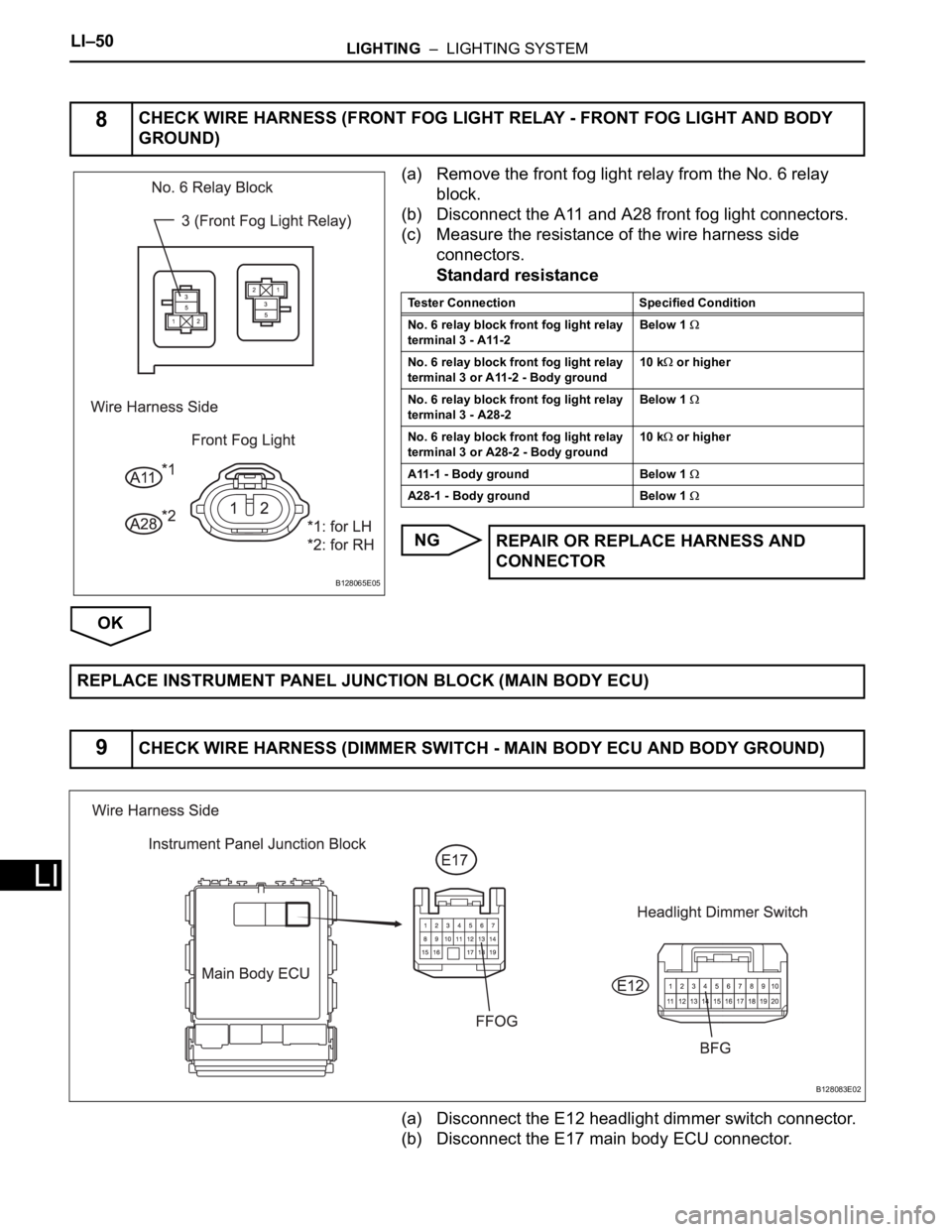
(a) Remove the front fog light relay from the No. 6 relay
block.
(b) Disconnect the A11 and A28 front fog light connectors.
(c) Measure the resistance of the wire harness side
connectors.
Standard resistance
NG
OK
(a) Disconnect the E12 headlight dimmer switch connector.
(b) Disconnect the E17 main body ECU connector.
8CHECK WIRE HARNESS (FRONT FOG LIGHT RELAY - FRONT FOG LIGHT AND BODY
GROUND)
B128065E05
Tester Connection Specified Condition
No. 6 relay block front fog light relay
terminal 3 - A11-2Below 1
No. 6 relay block front fog light relay
terminal 3 or A11-2 - Body ground10 k or higher
No. 6 relay block front fog light relay
terminal 3 - A28-2Below 1
No. 6 relay block front fog light relay
terminal 3 or A28-2 - Body ground10 k or higher
A11-1 - Body ground Below 1
A28-1 - Body ground Below 1
REPAIR OR REPLACE HARNESS AND
CONNECTOR
REPLACE INSTRUMENT PANEL JUNCTION BLOCK (MAIN BODY ECU)
9CHECK WIRE HARNESS (DIMMER SWITCH - MAIN BODY ECU AND BODY GROUND)
B128083E02
Page 1882 of 2000
LIGHTING – LIGHTING SYSTEMLI–51
LI
(c) Measure the resistance of the wire harness side
connectors.
Standard resistance
NG
OK
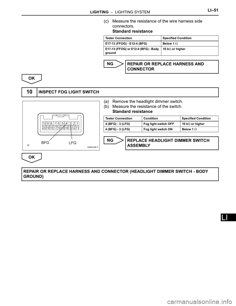
(a) Remove the headlight dimmer switch.
(b) Measure the resistance of the switch.
Standard resistance
NG
OK
Tester Connection Specified Condition
E17-13 (FFOG) - E12-4 (BFG) Below 1
E17-13 (FFOG) or E12-4 (BFG) - Body
ground10 k or higher
REPAIR OR REPLACE HARNESS AND
CONNECTOR
10INSPECT FOG LIGHT SWITCH
E068152E11
Tester Connection Condition Specified Condition
4 (BFG) - 3 (LFG) Fog light switch OFF 10 k
or higher
4 (BFG) - 3 (LFG) Fog light switch ON Below 1
REPLACE HEADLIGHT DIMMER SWITCH
ASSEMBLY
REPAIR OR REPLACE HARNESS AND CONNECTOR (HEADLIGHT DIMMER SWITCH - BODY
GROUND)
Page 1883 of 2000
LIGHTING – VANITY LIGHTLI–129
LI
(b) Inspect vanity light switch.
Standard resistance
If the result is not as specified, replace the visor
assembly.
INSTALLATION
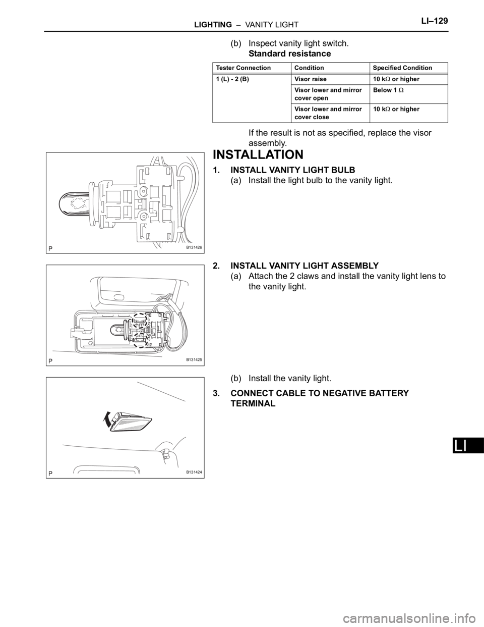
1. INSTALL VANITY LIGHT BULB
(a) Install the light bulb to the vanity light.
2. INSTALL VANITY LIGHT ASSEMBLY
(a) Attach the 2 claws and install the vanity light lens to
the vanity light.
(b) Install the vanity light.
3. CONNECT CABLE TO NEGATIVE BATTERY
TERMINAL
Tester Connection Condition Specified Condition
1 (L) - 2 (B) Visor raise 10 k
or higher
Visor lower and mirror
cover openBelow 1
Visor lower and mirror
cover close10 k or higher
B131426
B131425
B131424
Page 1884 of 2000
LI–134LIGHTING – HEADLIGHT DIMMER SWITCH
LI
REMOVAL
1. DISCONNECT CABLE FROM NEGATIVE BATTERY
TERMINAL
CAUTION:
Wait at least 90 seconds after disconnecting the
cable from the negative (-) battery terminal to
prevent airbag and seat belt pretensioner activation.
2. PLACE FRONT WHEELS FACING STRAIGHT AHEAD
3. REMOVE STEERING PAD ASSEMBLY (See page RS-
336)
4. REMOVE STEERING WHEEL ASSEMBLY (See page
SR-12)
5. REMOVE STEERING COLUMN COVER (See page
SR-12)
6. REMOVE SPIRAL CABLE SUB-ASSEMBLY (See page
RS-346)
7. REMOVE WIPER AND WASHER SWITCH (See page
WW-27)
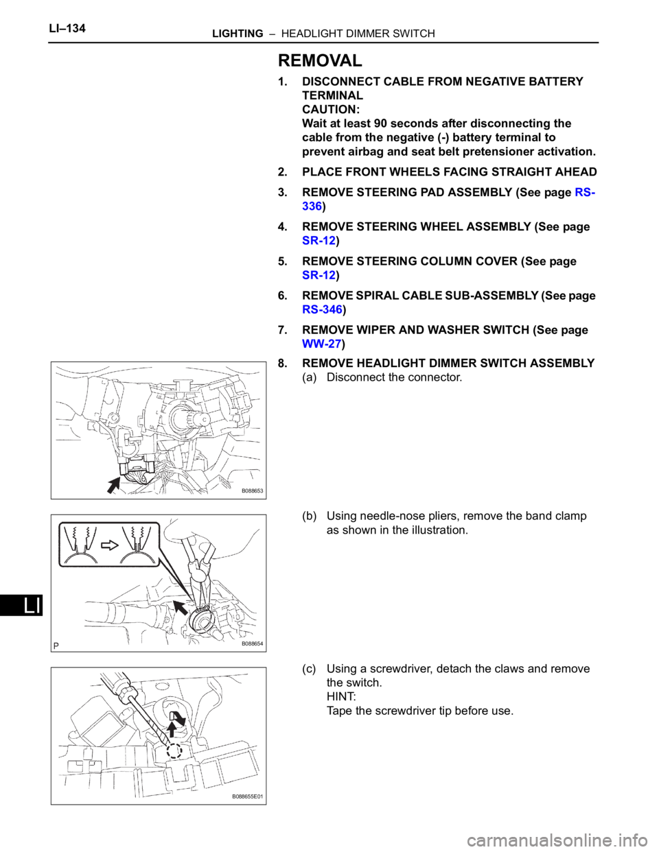
8. REMOVE HEADLIGHT DIMMER SWITCH ASSEMBLY
(a) Disconnect the connector.
(b) Using needle-nose pliers, remove the band clamp
as shown in the illustration.
(c) Using a screwdriver, detach the claws and remove
the switch.
HINT:
Tape the screwdriver tip before use.
B088653
B088654
B088655E01
Page 1885 of 2000
LIGHTING – HEADLIGHT DIMMER SWITCHLI–135
LI
INSPECTION
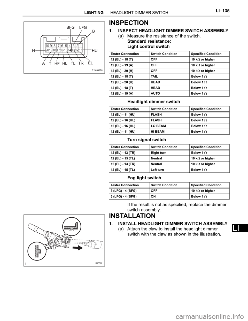
1. INSPECT HEADLIGHT DIMMER SWITCH ASSEMBLY
(a) Measure the resistance of the switch.
Standard resistance:
Light control switch
Headlight dimmer switch
Turn signal switch
Fog light switch
If the result is not as specified, replace the dimmer
switch assembly.
INSTALLATION
1. INSTALL HEADLIGHT DIMMER SWITCH ASSEMBLY
(a) Attach the claw to install the headlight dimmer
switch with the claw as shown in the illustration.
B136342E01
Tester Connection Switch Condition Specified Condition
12 (EL) - 18 (T) OFF 10 k
or higher
12 (EL) - 19 (A) OFF 10 k
or higher
12 (EL) - 20 (H) OFF 10 k
or higher
12 (EL) - 18 (T) TAIL Below 1
12 (EL) - 20 (H) HEAD Below 1
12 (EL) - 18 (T) HEAD Below 1
12 (EL) - 19 (A) AUTO Below 1
Tester Connection Switch Condition Specified Condition
12 (EL) - 11 (HU) FLASH Below 1
12 (EL) - 16 (HL) FLASH Below 1
12 (EL) - 16 (HL) LO BEAM Below 1
12 (EL) - 11 (HU) HI BEAM Below 1
Tester Connection Switch Condition Specified Condition
12 (EL) - 13 (TR) Right turn Below 1
12 (EL) - 15 (TL) Neutral 10 k or higher
12 (EL) - 13 (TR) Neutral 10 k
or higher
12 (EL) - 15 (TL) Left turn Below 1
Tester Connection Switch Condition Specified Condition
3 (LFG) - 4 (BFG) OFF 10 k
or higher
3 (LFG) - 4 (BFG) ON Below 1
B135621
Page 1886 of 2000
LI–136LIGHTING – HEADLIGHT DIMMER SWITCH
LI
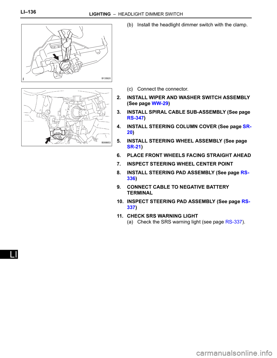
(b) Install the headlight dimmer switch with the clamp.
(c) Connect the connector.
2. INSTALL WIPER AND WASHER SWITCH ASSEMBLY
(See page WW-29)
3. INSTALL SPIRAL CABLE SUB-ASSEMBLY (See page
RS-347)
4. INSTALL STEERING COLUMN COVER (See page SR-
20)
5. INSTALL STEERING WHEEL ASSEMBLY (See page
SR-21)
6. PLACE FRONT WHEELS FACING STRAIGHT AHEAD
7. INSPECT STEERING WHEEL CENTER POINT
8. INSTALL STEERING PAD ASSEMBLY (See page RS-
336)
9. CONNECT CABLE TO NEGATIVE BATTERY
TERMINAL
10. INSPECT STEERING PAD ASSEMBLY (See page RS-
337)
11. CHECK SRS WARNING LIGHT
(a) Check the SRS warning light (see page RS-337).
B135620
B088653
Page 1887 of 2000
LIGHTING – FRONT DOOR COURTESY SWITCHLI–141
LI
INSTALLATION
HINT:
• Use the same procedures for the RH and LH sides.
• The procedures listed below are for the LH side.
• A bolt without a torque specification is shown in the
standard bolt chart (see page SS-2).
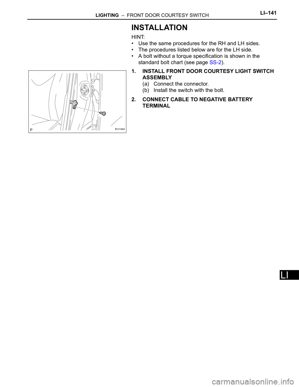
1. INSTALL FRONT DOOR COURTESY LIGHT SWITCH
ASSEMBLY
(a) Connect the connector.
(b) Install the switch with the bolt.
2. CONNECT CABLE TO NEGATIVE BATTERY
TERMINAL
B131444
Page 1888 of 2000
LIGHTING – REAR DOOR COURTESY SWITCHLI–143
LI
INSTALLATION
HINT:
• Use the same procedures for the RH and LH sides.
• The procedures listed below are for the LH side.
• A bolt without a torque specification is shown in the
standard bolt chart (see page SS-2).
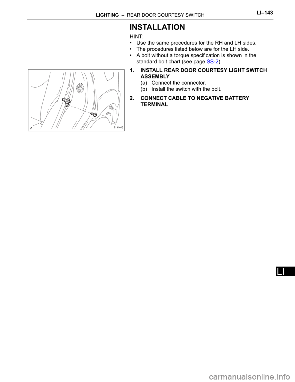
1. INSTALL REAR DOOR COURTESY LIGHT SWITCH
ASSEMBLY
(a) Connect the connector.
(b) Install the switch with the bolt.
2. CONNECT CABLE TO NEGATIVE BATTERY
TERMINAL
B131445
Page 1889 of 2000
LIGHTING – BACK DOOR COURTESY SWITCHLI–145
LI
INSTALLATION
HINT:
• Use the same procedures for the RH and LH sides.
• The procedures listed below are for the LH side.
• A bolt without a torque specification is shown in the
standard bolt chart (see page SS-2).
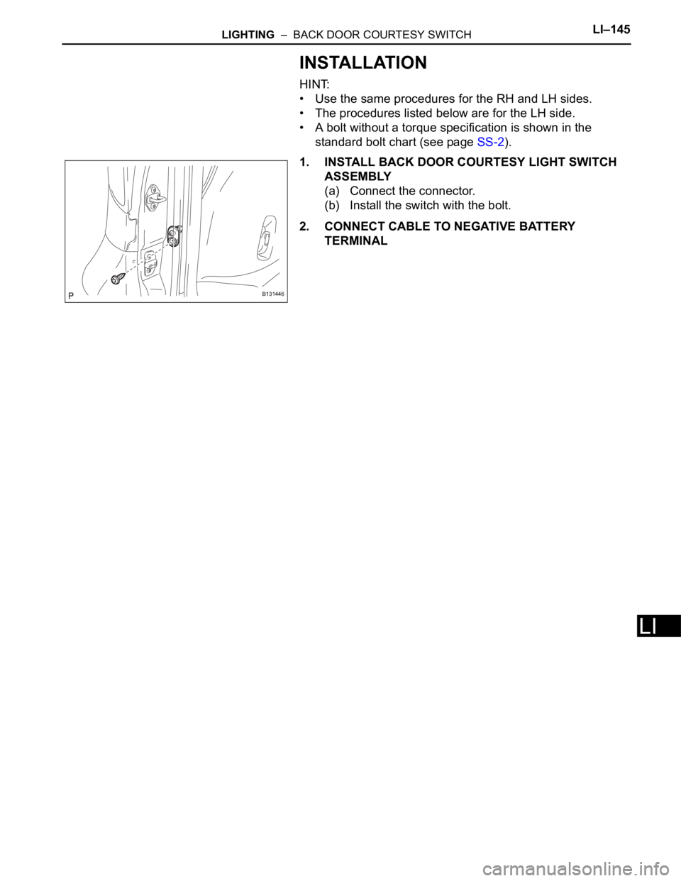
1. INSTALL BACK DOOR COURTESY LIGHT SWITCH
ASSEMBLY
(a) Connect the connector.
(b) Install the switch with the bolt.
2. CONNECT CABLE TO NEGATIVE BATTERY
TERMINAL
B131446
Page 1890 of 2000
WW–10WIPER AND WASHER – FRONT WIPER MOTOR AND LINK
WW
INSPECTION
1. INSPECT WINDSHIELD WIPER MOTOR ASSEMBLY
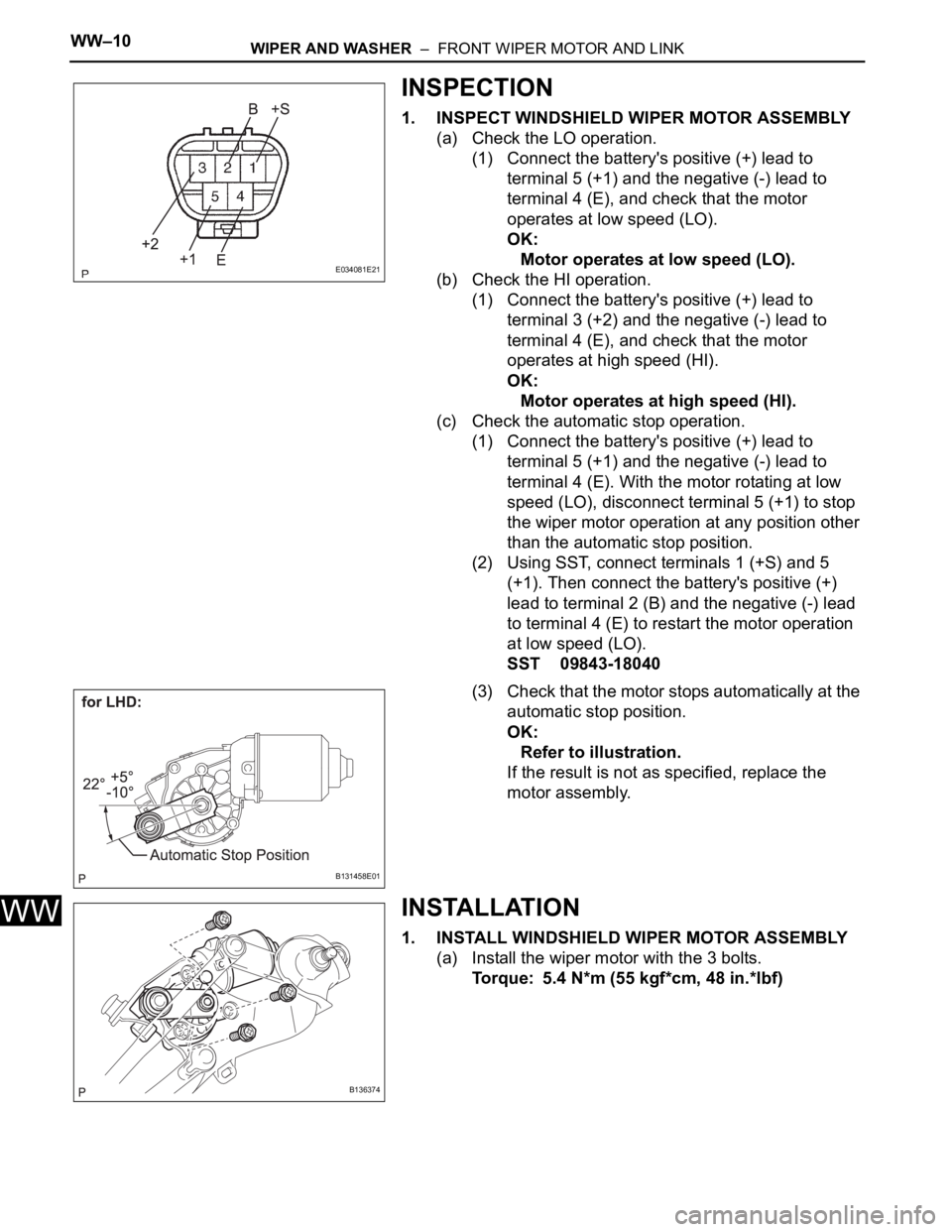
(a) Check the LO operation.
(1) Connect the battery's positive (+) lead to
terminal 5 (+1) and the negative (-) lead to
terminal 4 (E), and check that the motor
operates at low speed (LO).
OK:
Motor operates at low speed (LO).
(b) Check the HI operation.
(1) Connect the battery's positive (+) lead to
terminal 3 (+2) and the negative (-) lead to
terminal 4 (E), and check that the motor
operates at high speed (HI).
OK:
Motor operates at high speed (HI).
(c) Check the automatic stop operation.
(1) Connect the battery's positive (+) lead to
terminal 5 (+1) and the negative (-) lead to
terminal 4 (E). With the motor rotating at low
speed (LO), disconnect terminal 5 (+1) to stop
the wiper motor operation at any position other
than the automatic stop position.
(2) Using SST, connect terminals 1 (+S) and 5
(+1). Then connect the battery's positive (+)
lead to terminal 2 (B) and the negative (-) lead
to terminal 4 (E) to restart the motor operation
at low speed (LO).
SST 09843-18040
(3) Check that the motor stops automatically at the
automatic stop position.
OK:
Refer to illustration.
If the result is not as specified, replace the
motor assembly.
INSTALLATION
1. INSTALL WINDSHIELD WIPER MOTOR ASSEMBLY
(a) Install the wiper motor with the 3 bolts.
Torque: 5.4 N*m (55 kgf*cm, 48 in.*lbf)
E034081E21
B131458E01
B136374