Washer TOYOTA RAV4 2006 Service User Guide
[x] Cancel search | Manufacturer: TOYOTA, Model Year: 2006, Model line: RAV4, Model: TOYOTA RAV4 2006Pages: 2000, PDF Size: 45.84 MB
Page 660 of 2000
2AZ-FE ENGINE MECHANICAL – ENGINE UNITEM–133
EM
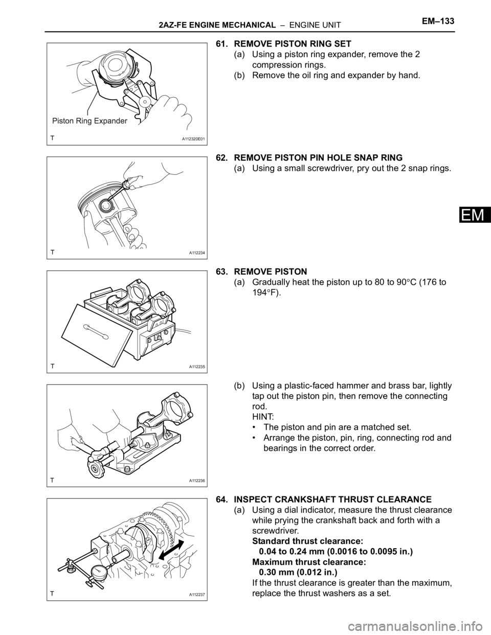
61. REMOVE PISTON RING SET
(a) Using a piston ring expander, remove the 2
compression rings.
(b) Remove the oil ring and expander by hand.
62. REMOVE PISTON PIN HOLE SNAP RING
(a) Using a small screwdriver, pry out the 2 snap rings.
63. REMOVE PISTON
(a) Gradually heat the piston up to 80 to 90
C (176 to
194
F).
(b) Using a plastic-faced hammer and brass bar, lightly
tap out the piston pin, then remove the connecting
rod.
HINT:
• The piston and pin are a matched set.
• Arrange the piston, pin, ring, connecting rod and
bearings in the correct order.
64. INSPECT CRANKSHAFT THRUST CLEARANCE
(a) Using a dial indicator, measure the thrust clearance
while prying the crankshaft back and forth with a
screwdriver.
Standard thrust clearance:
0.04 to 0.24 mm (0.0016 to 0.0095 in.)
Maximum thrust clearance:
0.30 mm (0.012 in.)
If the thrust clearance is greater than the maximum,
replace the thrust washers as a set.
A112320E01
A112234
A112235
A112236
A112237
Page 661 of 2000
EM–1342AZ-FE ENGINE MECHANICAL – ENGINE UNIT
EM
HINT:
The thrust washer thickness is 1.93 to 1.98 mm
(0.0760 to 0.0780 in.).
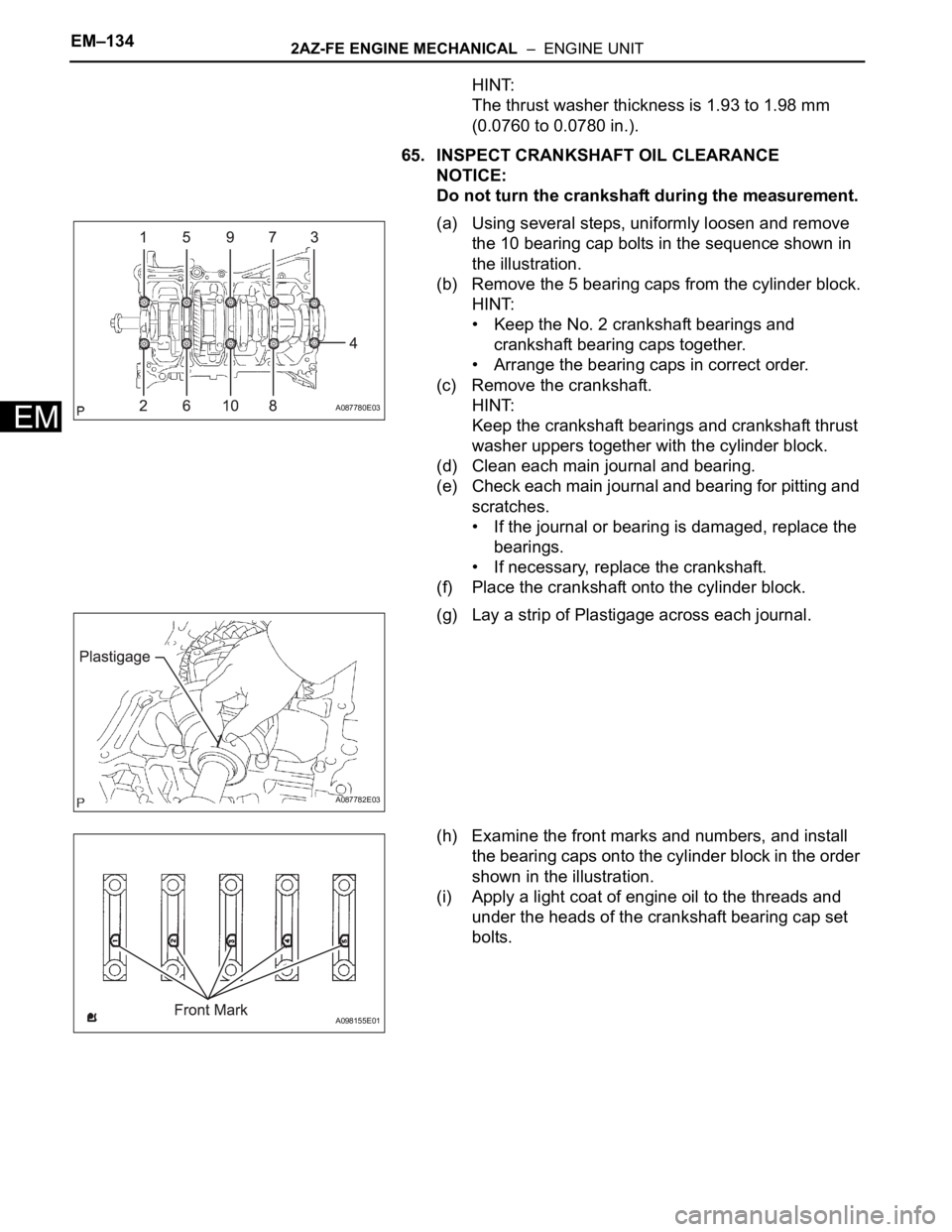
65. INSPECT CRANKSHAFT OIL CLEARANCE
NOTICE:
Do not turn the crankshaft during the measurement.
(a) Using several steps, uniformly loosen and remove
the 10 bearing cap bolts in the sequence shown in
the illustration.
(b) Remove the 5 bearing caps from the cylinder block.
HINT:
• Keep the No. 2 crankshaft bearings and
crankshaft bearing caps together.
• Arrange the bearing caps in correct order.
(c) Remove the crankshaft.
HINT:
Keep the crankshaft bearings and crankshaft thrust
washer uppers together with the cylinder block.
(d) Clean each main journal and bearing.
(e) Check each main journal and bearing for pitting and
scratches.
• If the journal or bearing is damaged, replace the
bearings.
• If necessary, replace the crankshaft.
(f) Place the crankshaft onto the cylinder block.
(g) Lay a strip of Plastigage across each journal.
(h) Examine the front marks and numbers, and install
the bearing caps onto the cylinder block in the order
shown in the illustration.
(i) Apply a light coat of engine oil to the threads and
under the heads of the crankshaft bearing cap set
bolts.
A087780E03
A087782E03
A098155E01
Page 664 of 2000
2AZ-FE ENGINE MECHANICAL – ENGINE UNITEM–137
EM
Standard bearing center wall thickness
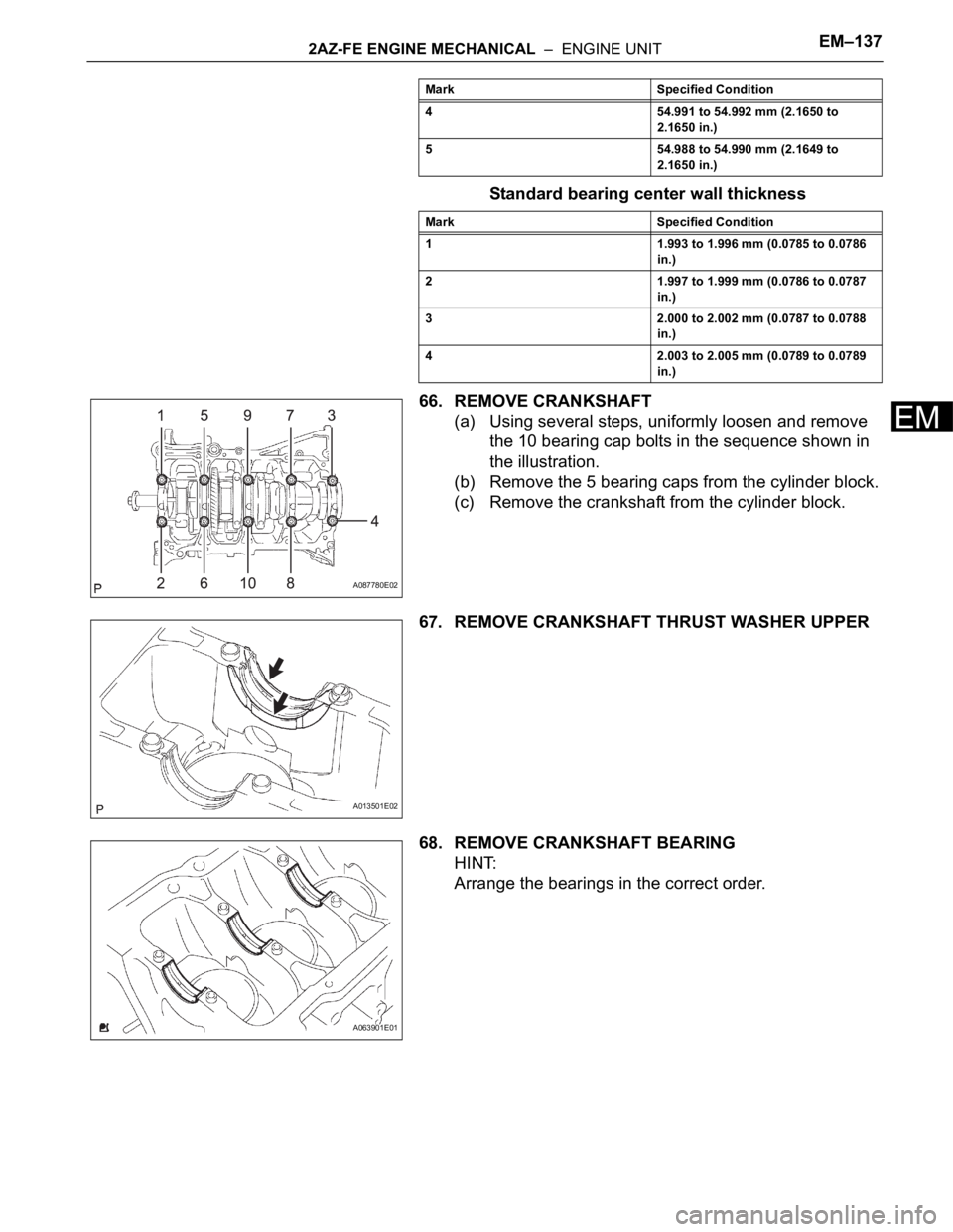
66. REMOVE CRANKSHAFT
(a) Using several steps, uniformly loosen and remove
the 10 bearing cap bolts in the sequence shown in
the illustration.
(b) Remove the 5 bearing caps from the cylinder block.
(c) Remove the crankshaft from the cylinder block.
67. REMOVE CRANKSHAFT THRUST WASHER UPPER
68. REMOVE CRANKSHAFT BEARING
HINT:
Arrange the bearings in the correct order.
4 54.991 to 54.992 mm (2.1650 to
2.1650 in.)
5 54.988 to 54.990 mm (2.1649 to
2.1650 in.)
Mark Specified Condition
1 1.993 to 1.996 mm (0.0785 to 0.0786
in.)
2 1.997 to 1.999 mm (0.0786 to 0.0787
in.)
3 2.000 to 2.002 mm (0.0787 to 0.0788
in.)
4 2.003 to 2.005 mm (0.0789 to 0.0789
in.) Mark Specified Condition
A087780E02
A013501E02
A063901E01
Page 698 of 2000
2GR-FE ENGINE MECHANICAL – ENGINE UNITEM–61
EM
39. REMOVE VALVE LASH ADJUSTER ASSEMBLY
(a) Remove the 24 valve lash adjusters from the
cylinder head.
HINT:
Arrange the removed parts in the correct order.
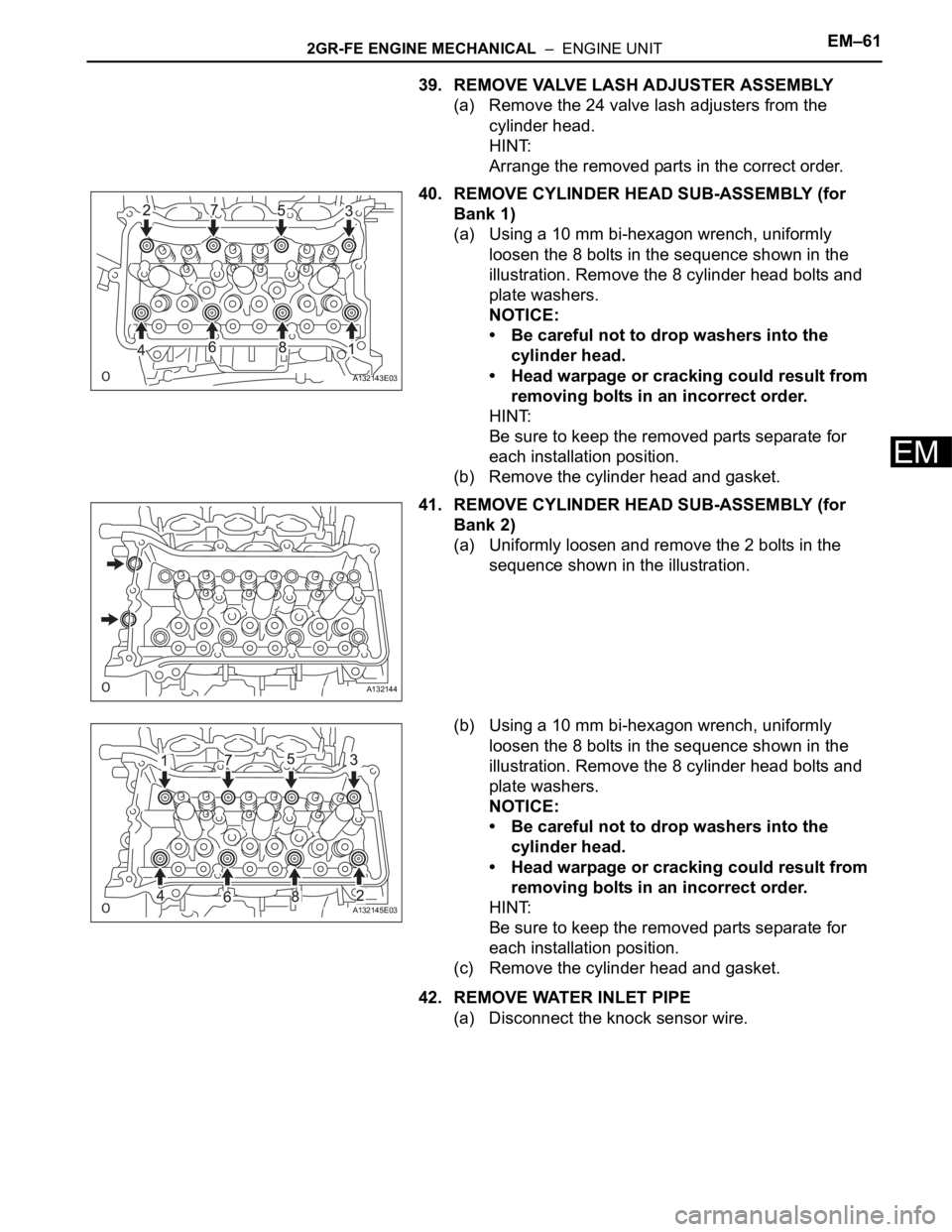
40. REMOVE CYLINDER HEAD SUB-ASSEMBLY (for
Bank 1)
(a) Using a 10 mm bi-hexagon wrench, uniformly
loosen the 8 bolts in the sequence shown in the
illustration. Remove the 8 cylinder head bolts and
plate washers.
NOTICE:
• Be careful not to drop washers into the
cylinder head.
• Head warpage or cracking could result from
removing bolts in an incorrect order.
HINT:
Be sure to keep the removed parts separate for
each installation position.
(b) Remove the cylinder head and gasket.
41. REMOVE CYLINDER HEAD SUB-ASSEMBLY (for
Bank 2)
(a) Uniformly loosen and remove the 2 bolts in the
sequence shown in the illustration.
(b) Using a 10 mm bi-hexagon wrench, uniformly
loosen the 8 bolts in the sequence shown in the
illustration. Remove the 8 cylinder head bolts and
plate washers.
NOTICE:
• Be careful not to drop washers into the
cylinder head.
• Head warpage or cracking could result from
removing bolts in an incorrect order.
HINT:
Be sure to keep the removed parts separate for
each installation position.
(c) Remove the cylinder head and gasket.
42. REMOVE WATER INLET PIPE
(a) Disconnect the knock sensor wire.
A132143E03
A132144
A132145E03
Page 704 of 2000
2GR-FE ENGINE MECHANICAL – ENGINE UNITEM–67
EM
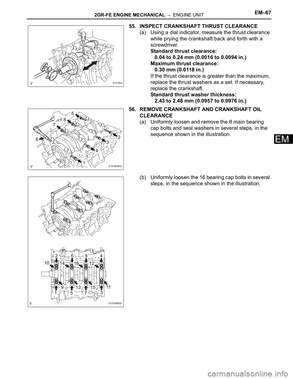
55. INSPECT CRANKSHAFT THRUST CLEARANCE
(a) Using a dial indicator, measure the thrust clearance
while prying the crankshaft back and forth with a
screwdriver.
Standard thrust clearance:
0.04 to 0.24 mm (0.0016 to 0.0094 in.)
Maximum thrust clearance:
0.30 mm (0.0118 in.)
If the thrust clearance is greater than the maximum,
replace the thrust washers as a set. If necessary,
replace the crankshaft.
Standard thrust washer thickness:
2.43 to 2.48 mm (0.0957 to 0.0976 in.)
56. REMOVE CRANKSHAFT AND CRANKSHAFT OIL
CLEARANCE
(a) Uniformly loosen and remove the 8 main bearing
cap bolts and seal washers in several steps, in the
sequence shown in the illustration.
(b) Uniformly loosen the 16 bearing cap bolts in several
steps, in the sequence shown in the illustration.
A131934
A131935E01
A131936E01
Page 710 of 2000
2GR-FE ENGINE MECHANICAL – ENGINE UNITEM–73
EM
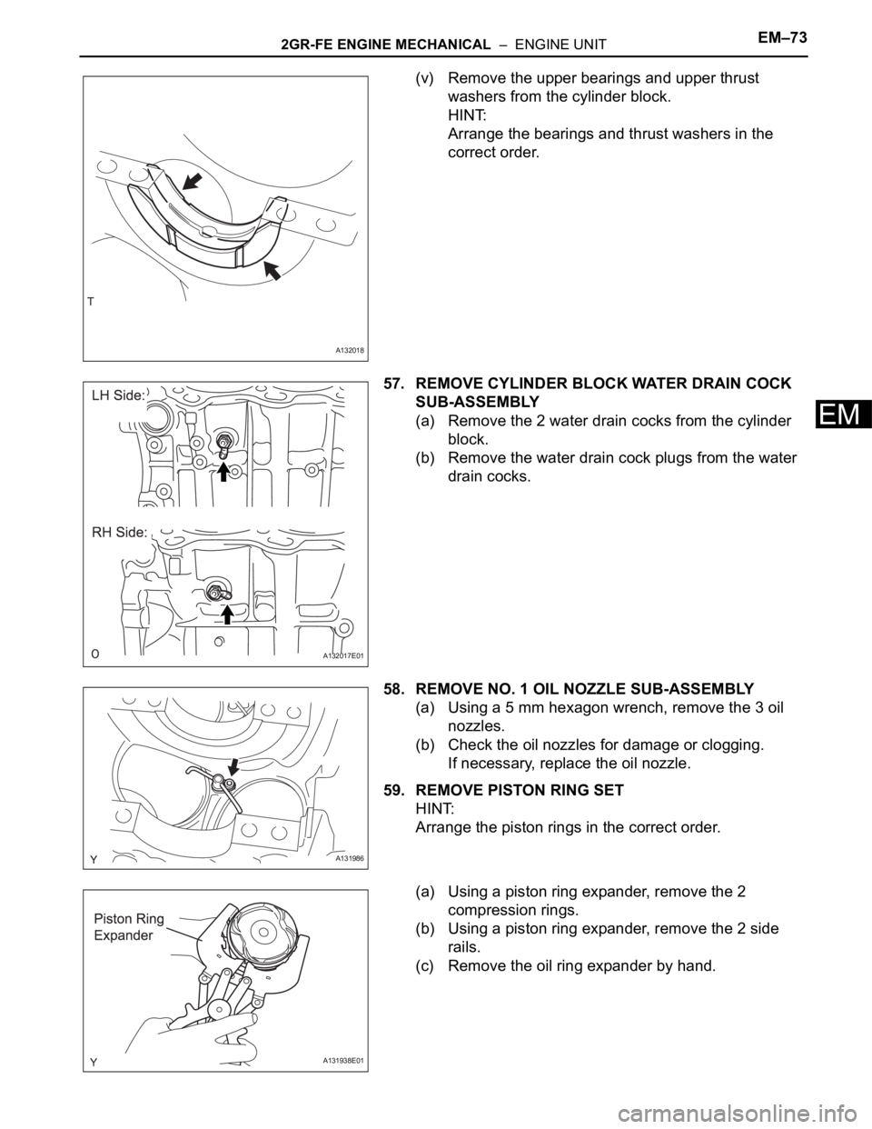
(v) Remove the upper bearings and upper thrust
washers from the cylinder block.
HINT:
Arrange the bearings and thrust washers in the
correct order.
57. REMOVE CYLINDER BLOCK WATER DRAIN COCK
SUB-ASSEMBLY
(a) Remove the 2 water drain cocks from the cylinder
block.
(b) Remove the water drain cock plugs from the water
drain cocks.
58. REMOVE NO. 1 OIL NOZZLE SUB-ASSEMBLY
(a) Using a 5 mm hexagon wrench, remove the 3 oil
nozzles.
(b) Check the oil nozzles for damage or clogging.
If necessary, replace the oil nozzle.
59. REMOVE PISTON RING SET
HINT:
Arrange the piston rings in the correct order.
(a) Using a piston ring expander, remove the 2
compression rings.
(b) Using a piston ring expander, remove the 2 side
rails.
(c) Remove the oil ring expander by hand.
A132018
A132017E01
A131986
A131938E01
Page 746 of 2000
2GR-FE ENGINE MECHANICAL – ENGINE UNITEM–109
EM
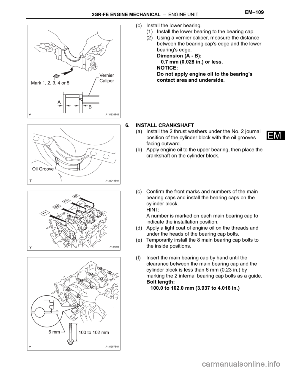
(c) Install the lower bearing.
(1) Install the lower bearing to the bearing cap.
(2) Using a vernier caliper, measure the distance
between the bearing cap's edge and the lower
bearing's edge.
Dimension (A - B):
0.7 mm (0.028 in.) or less.
NOTICE:
Do not apply engine oil to the bearing's
contact area and underside.
6. INSTALL CRANKSHAFT
(a) Install the 2 thrust washers under the No. 2 journal
position of the cylinder block with the oil grooves
facing outward.
(b) Apply engine oil to the upper bearing, then place the
crankshaft on the cylinder block.
(c) Confirm the front marks and numbers of the main
bearing caps and install the bearing caps on the
cylinder block.
HINT:
A number is marked on each main bearing cap to
indicate the installation position.
(d) Apply a light coat of engine oil on the threads and
under the heads of the bearing cap bolts.
(e) Temporarily install the 8 main bearing cap bolts to
the inside positions.
(f) Insert the main bearing cap by hand until the
clearance between the main bearing cap and the
cylinder block is less than 6 mm (0.23 in.) by
marking the 2 internal bearing cap bolts as a guide.
Bolt length:
100.0 to 102.0 mm (3.937 to 4.016 in.)
A131826E02
A132044E01
A131988
A131957E01
Page 753 of 2000
EM–1162GR-FE ENGINE MECHANICAL – ENGINE UNIT
EM
17. INSTALL WATER INLET PIPE
(a) Install the water inlet pipe with the 2 bolts.
Torque: 10 N*m (102 kgf*cm, 7 ft.*lbf)
(b) Install the water by-pass hose.
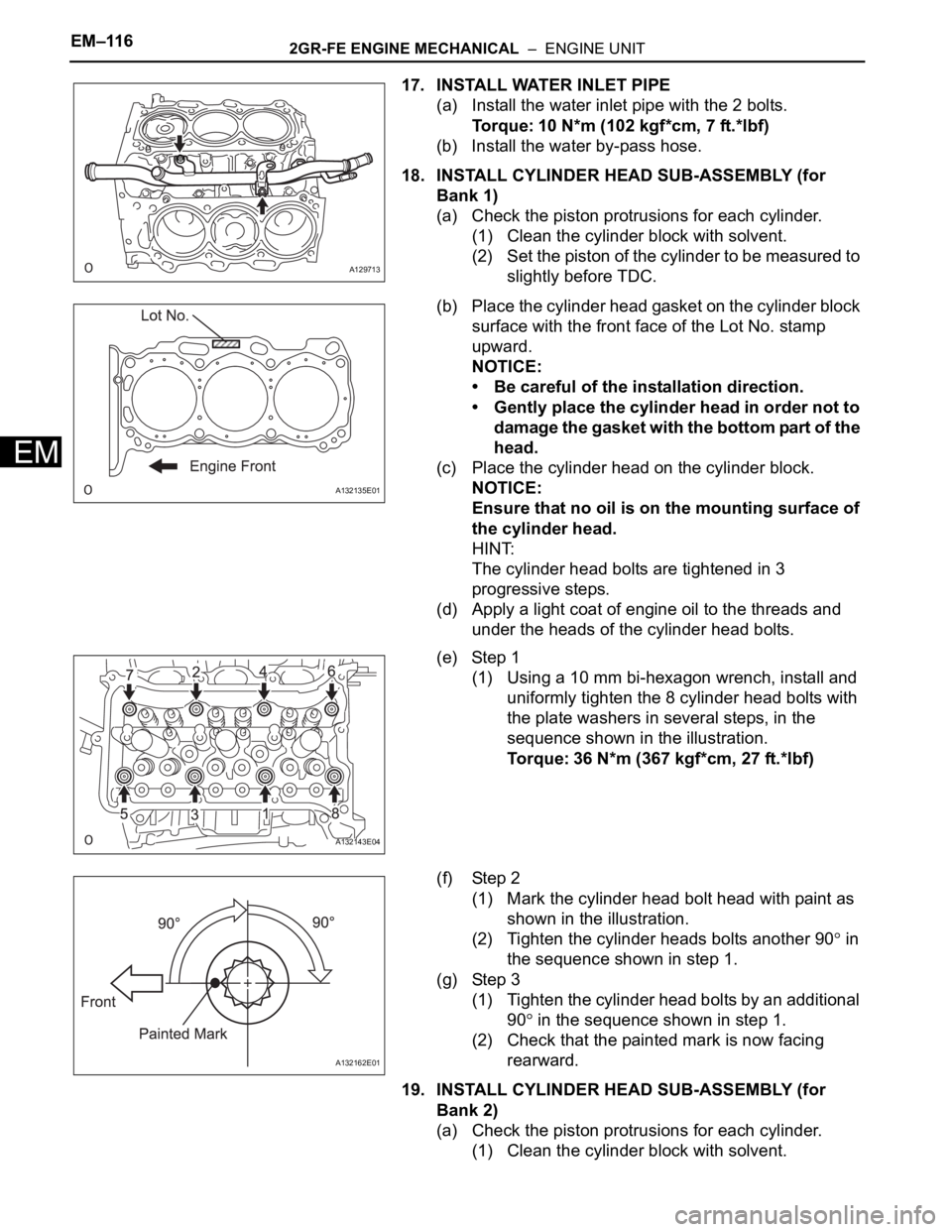
18. INSTALL CYLINDER HEAD SUB-ASSEMBLY (for
Bank 1)
(a) Check the piston protrusions for each cylinder.
(1) Clean the cylinder block with solvent.
(2) Set the piston of the cylinder to be measured to
slightly before TDC.
(b) Place the cylinder head gasket on the cylinder block
surface with the front face of the Lot No. stamp
upward.
NOTICE:
• Be careful of the installation direction.
• Gently place the cylinder head in order not to
damage the gasket with the bottom part of the
head.
(c) Place the cylinder head on the cylinder block.
NOTICE:
Ensure that no oil is on the mounting surface of
the cylinder head.
HINT:
The cylinder head bolts are tightened in 3
progressive steps.
(d) Apply a light coat of engine oil to the threads and
under the heads of the cylinder head bolts.
(e) Step 1
(1) Using a 10 mm bi-hexagon wrench, install and
uniformly tighten the 8 cylinder head bolts with
the plate washers in several steps, in the
sequence shown in the illustration.
Torque: 36 N*m (367 kgf*cm, 27 ft.*lbf)
(f) Step 2
(1) Mark the cylinder head bolt head with paint as
shown in the illustration.
(2) Tighten the cylinder heads bolts another 90
in
the sequence shown in step 1.
(g) Step 3
(1) Tighten the cylinder head bolts by an additional
90
in the sequence shown in step 1.
(2) Check that the painted mark is now facing
rearward.
19. INSTALL CYLINDER HEAD SUB-ASSEMBLY (for
Bank 2)
(a) Check the piston protrusions for each cylinder.
(1) Clean the cylinder block with solvent.
A129713
A132135E01
A132143E04
A132162E01
Page 754 of 2000
2GR-FE ENGINE MECHANICAL – ENGINE UNITEM–117
EM
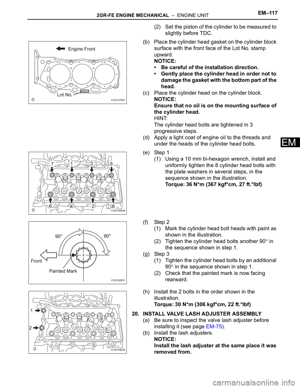
(2) Set the piston of the cylinder to be measured to
slightly before TDC.
(b) Place the cylinder head gasket on the cylinder block
surface with the front face of the Lot No. stamp
upward.
NOTICE:
• Be careful of the installation direction.
• Gently place the cylinder head in order not to
dama ge the gaske t wi th t he b ottom part of t he
head.
(c) Place the cylinder head on the cylinder block.
NOTICE:
Ensure that no oil is on the mounting surface of
the cylinder head.
HINT:
The cylinder head bolts are tightened in 3
progressive steps.
(d) Apply a light coat of engine oil to the threads and
under the heads of the cylinder head bolts.
(e) Step 1
(1) Using a 10 mm bi-hexagon wrench, install and
uniformly tighten the 8 cylinder head bolts with
the plate washers in several steps, in the
sequence shown in the illustration.
Torque: 36 N*m (367 kgf*cm, 27 ft.*lbf)
(f) Step 2
(1) Mark the cylinder head bolt heads with paint as
shown in the illustration.
(2) Tighten the cylinder head bolts another 90
in
the sequence shown in step 1.
(g) Step 3
(1) Tighten the cylinder head bolts by an additional
90
in the sequence shown in step 1.
(2) Check that the painted mark is now facing
rearward.
(h) Install the 2 bolts in the order shown in the
illustration.
Torque: 30 N*m (306 kgf*cm, 22 ft.*lbf)
20. INSTALL VALVE LASH ADJUSTER ASSEMBLY
(a) Be sure to inspect the valve lash adjuster before
installing it (see page EM-75).
(b) Install the lash adjusters.
NOTICE:
Install the lash adjuster at the same place it was
removed from.
A132137E01
A132145E04
A132162E01
A132144E02
Page 900 of 2000
ST–82AZ-FE STARTING – STARTER
ST
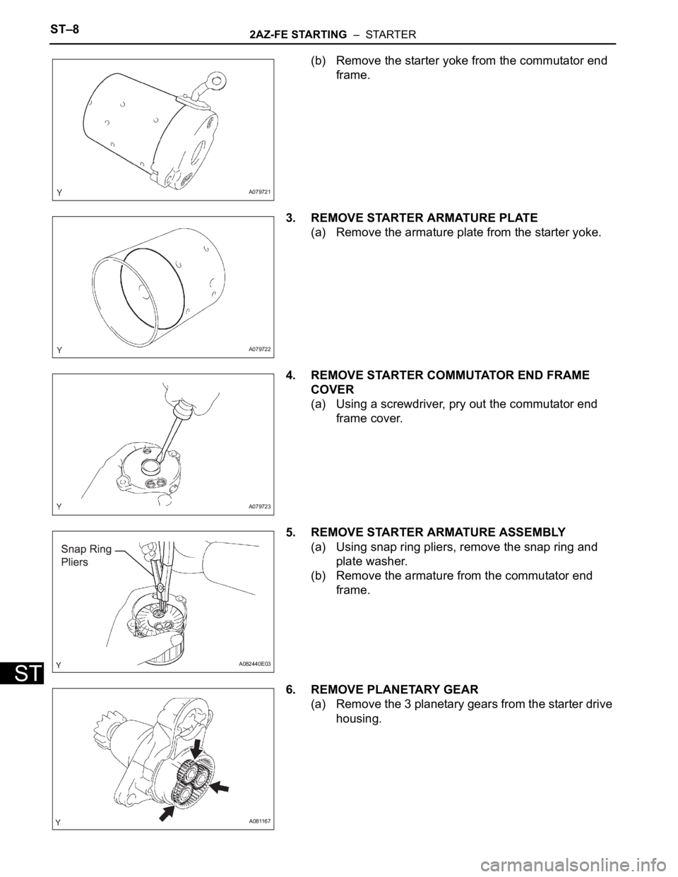
(b) Remove the starter yoke from the commutator end
frame.
3. REMOVE STARTER ARMATURE PLATE
(a) Remove the armature plate from the starter yoke.
4. REMOVE STARTER COMMUTATOR END FRAME
COVER
(a) Using a screwdriver, pry out the commutator end
frame cover.
5. REMOVE STARTER ARMATURE ASSEMBLY
(a) Using snap ring pliers, remove the snap ring and
plate washer.
(b) Remove the armature from the commutator end
frame.
6. REMOVE PLANETARY GEAR
(a) Remove the 3 planetary gears from the starter drive
housing.
A079721
A079722
A079723
A082440E03
A081167