cooling TOYOTA RAV4 2006 Service User Guide
[x] Cancel search | Manufacturer: TOYOTA, Model Year: 2006, Model line: RAV4, Model: TOYOTA RAV4 2006Pages: 2000, PDF Size: 45.84 MB
Page 93 of 2000

ENGINE - 2GR-FE ENGINE
285EG40
Iridium Tip
Platinum Tip
Wa t e r J a c k e t Long-reach
Ty p eConventional
Ty p eEG-97
3. Spark Plug
Long-reach type spark plugs are used. This type of spark plugs allow the area of the cylinder head to
receive the spark plugs to be made thick. Thus, the water jacket can be extended near the combustion
chamber, which contributes to cooling performance.
Iridium-tipped spark plugs are used to achieve a 120,000 miles (193,000 km) maintenance interval. By
making the center electrode of iridium, the superior ignition performance as platinum-tipped spark plugs
is achieved and durability has been increased.
Page 97 of 2000

ENGINE - 2GR-FE ENGINEEG-101
ENGINE CONTROL SYSTEM
1. General
The engine control system of the 2GR-FE engine has the following features.
System
Outline
SFI
(Sequential Multiport
Fuel Injection)
[See page EG-117]
An L-type SFI system detects the intake air mass with a hot-wire type air
flow meter.
ESA
(Electronic Spark
Advance)
Ignition timing is determined by the ECM based on signals from various
sensors. The ECM corrects ignition timing in response to engine
knocking.
This system selects the optimal ignition timing in accordance with the
signals received from the sensors and sends the (IGT) ignition signal to
the igniter.
ETCS-i
(Electronic Throttle
Control
System-intelligent)
[See page EG-118]
Optimally controls the throttle valve opening in accordance with the amount
of accelerator pedal effort and the condition of the engine and the vehicle.
Dual VVT-i
(Variable Valve
Timing-intelligent)
System
[See page EG-120]
Controls the intake and exhaust camshafts to an optimal valve timing in
accordance with the engine condition.
ACIS
(Acoustic Control
Induction System)
[See page EG-126]The intake air passages are switched according to the engine speed and
throttle valve opening angle to provided high performance in all speed
ranges.
Air Intake Control
System
[See page EG-128]The intake air duct is divided into two areas, and the ECM controls the air
intake control valve and the actuator that are provided in one of the areas to
reduce the amount of engine noise.
Fuel Pump Control
[See page EG-53 in
2AZ-FE section]Fuel pump operation is controlled by signals from the ECM.
The fuel pump is stopped, when the SRS airbag is deployed in a frontal,
side, and rear side collision.
Air Conditioning Cut-off
ControlBy turning the air conditioning compressor ON or OFF in accordance with
the engine condition, drivability is maintained.
Charging Control
[See page EG-65 in
2AZ-FE section]The engine ECU regulates the charging voltage of the generator in
accordance with the driving conditions and the charging state of the battery.
Cooling Fan Control
[See page EG-129]
The cooling fan ECU steplessly controls the speed of the fans in accordance
with the engine coolant temperature, vehicle speed, engine speed, and air
conditioning operating conditions. As a result, the cooling performance is
improved.
(Continued)
Page 101 of 2000

ENGINE - 2GR-FE ENGINE
01MEG08Y
DEFOGGER RELAY
TA I L L A M P R E L AY
STOP LIGHT SWITCH
CRUISE CONTROL SWITCH
AIR CONDITIONING ECU
AIRBAG SENSOR
ASSEMBLY
SKID CONTROL ECU
DLC3
MAIN RELAY
BATTERYELS
ELS2
STP
CCS
CANH,
CANL
TC
TA C H
MREL
+B
BATTECMRFC
RFC
MPMP
VPMP
PRG
WCOOLING FAN CONTROL*1
COOLING FAN ECU
FAN MOTOR NO. 1 AND
NO. 2
COOLING FAN CONTROL*
2
COOLING FAN ECU NO. 1
FAN MOTOR NO. 1
COOLING FAN ECU NO. 2
FAN MOTOR NO. 2
EVAPORATIVE EMISSION
CONTROL
LEAK DETECTION
PUMP
VENT VALVE
PURGE VSV
COMBINATION METER
MIL
: CANEG-105
*
1: Except Towing Package Models
*
2: Towing Package Models
Page 102 of 2000

ENGINE - 2GR-FE ENGINE
01MEG29Y
Ignition SwitchCombination Meter
Vehicle Speed Signal
MIL
Battery Current Sensor
(Built-in Battery
Temperature Sensor)
Park / Neutral
Position Switch
Battery
Generator
Fuel Pump Relay
Fuel Pump
Vent Valve
Circuit Opening
RelayDLC3*1*2*3
CAN
ECM
Cruise Control Switch
Accelerator Pedal
Position Sensor
Stop Light Switch
Canister
Pressure
SensorLeak
Detection
Pump
Intake Air
Temp. Sensor
VSV (For
Air Intake
Control)Mass Air
Flow Meter
AirThrottle Position
Sensor
Purge VSV
Throttle
Control
Motor
*4*5
Fan
Motor No. 1Fan
Motor
No. 2
Cooling
Fan
ECUCooling
Fan
ECU
No. 1Cooling
Fan
ECU
No. 2
Fan Motor No. 1
Fan Motor No. 2
ACIS Actuator
Intake Camshaft Timing
Oil Control Valve (Bank 2)Injector Injector
Intake Camshaft Timing
Oil Control Valve (Bank 1)
Intake VVT Sensor (Bank 1)
Ignition Coil With Igniter
Exhaust VVT Sensor (Bank 1)
Exhaust Camshaft Timing
Oil Control Valve (Bank 1)
Air-fuel Ratio Sensor
(Bank1, Sensor1)
TWC
Knock
Sensor
Intake VVT
Sensor (Bank 2)
Exhaust VVT
Sensor (Bank 2)
Air-fuel Ratio Sensor
(Bank2, Sensor1)Exhaust Camshaft
Timing Oil Control
Valve (Bank 2)
Crankshaft Position
Sensor
Engine Coolant
Temperature Sensor Heated Oxygen Sensor
(Bank1, Sensor2)Heated Oxygen Sensor
(Bank2, Sensor2)TWCTWC
EG-106
3. Engine Control System Diagram
*1: Air Conditioning ECU
*
2: Airbag Sensor Assembly
*
3: Skid Control ECU
*
4: Except Towing Package Models
*
5: Towing Package Models
Page 125 of 2000

ENGINE - 2GR-FE ENGINE
01MEG21Y
01MEG22Y
Engine Coolant Temperature
Sensor
Crankshaft Position Sensor
Combination Meter
Vehicle Speed SignalECM
CAN
Air Conditioning ECUCooling
Fan
ECUFan Motor
No. 1
Fan Motor
No. 2
Except Towing Package Models
Towing Package Models Engine Coolant Temperature
Sensor
Crankshaft Position Sensor
Combination Meter
Vehicle Speed SignalECM
CAN
Air Conditioning ECUCooling
Fan
ECU
No. 1
Cooling
Fan
ECU
No. 2Fan Motor
No. 1
Fan Motor
No. 2EG-129
12. Cooling Fan Control System
General
A cooling fan control system is used. To achieve an optimal fan speed in accordance with the engine coolant
temperature, vehicle speed, engine speed, and air conditioning operating conditions, the ECM calculates
the proper fan speed and sends the signals to the front controller. By receiving the signals from the ECM,
the front controller sends proper fan speed control signals to the cooling fan ECU.
Upon receiving the signals from the front controller, the cooling fan ECU actuates the fan motors.
Wiring Diagram
Page 172 of 2000

PP–22PREPARATION – 2AZ-FE COOLING
PP
EQUIPMENT
Ohmmeter -
Radiator cap tester -
Thermometer -
To r q u e w r e n c h -
Slide calipers -
Heater -
Page 173 of 2000

PREPARATION – 2AZ-FE COOLINGPP–23
PP
COOLANT
Capacity Classification
6.8 liters (7.2 US qts, 5.9 Imp. qts) Use only "TOYOTA Super Long Life Coolant" or similar high quality
ethylene glycol based non-silicate, non-amine, non-nitrite, non-borate
coolant with long-life hybrid organic acid technology (coolant with
long-life hybrid organic acid technology consists of a combination of
low phosphates and organic acids).
Page 240 of 2000
CO–42AZ-FE COOLING – COOLING FAN SYSTEM
CO
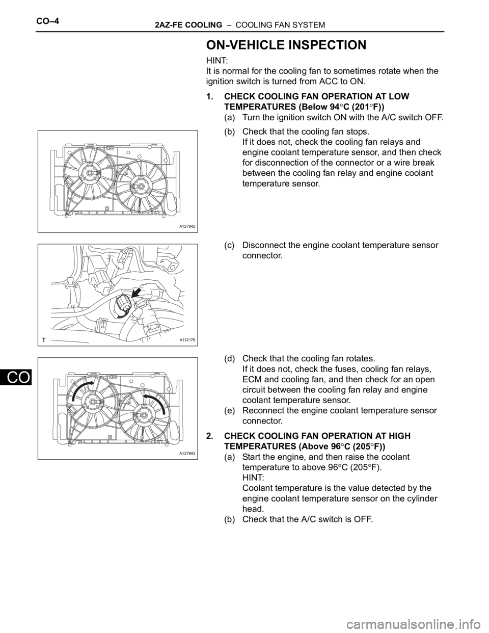
ON-VEHICLE INSPECTION
HINT:
It is normal for the cooling fan to sometimes rotate when the
ignition switch is turned from ACC to ON.
1. CHECK COOLING FAN OPERATION AT LOW
TEMPERATURES (Below 94
C (201F))
(a) Turn the ignition switch ON with the A/C switch OFF.
(b) Check that the cooling fan stops.
If it does not, check the cooling fan relays and
engine coolant temperature sensor, and then check
for disconnection of the connector or a wire break
between the cooling fan relay and engine coolant
temperature sensor.
(c) Disconnect the engine coolant temperature sensor
connector.
(d) Check that the cooling fan rotates.
If it does not, check the fuses, cooling fan relays,
ECM and cooling fan, and then check for an open
circuit between the cooling fan relay and engine
coolant temperature sensor.
(e) Reconnect the engine coolant temperature sensor
connector.
2. CHECK COOLING FAN OPERATION AT HIGH
TEMPERATURES (Above 96
C (205F))
(a) Start the engine, and then raise the coolant
temperature to above 96
C (205F).
HINT:
Coolant temperature is the value detected by the
engine coolant temperature sensor on the cylinder
head.
(b) Check that the A/C switch is OFF.
A127842
A112176
A127843
Page 241 of 2000
2AZ-FE COOLING – COOLING FAN SYSTEMCO–5
CO
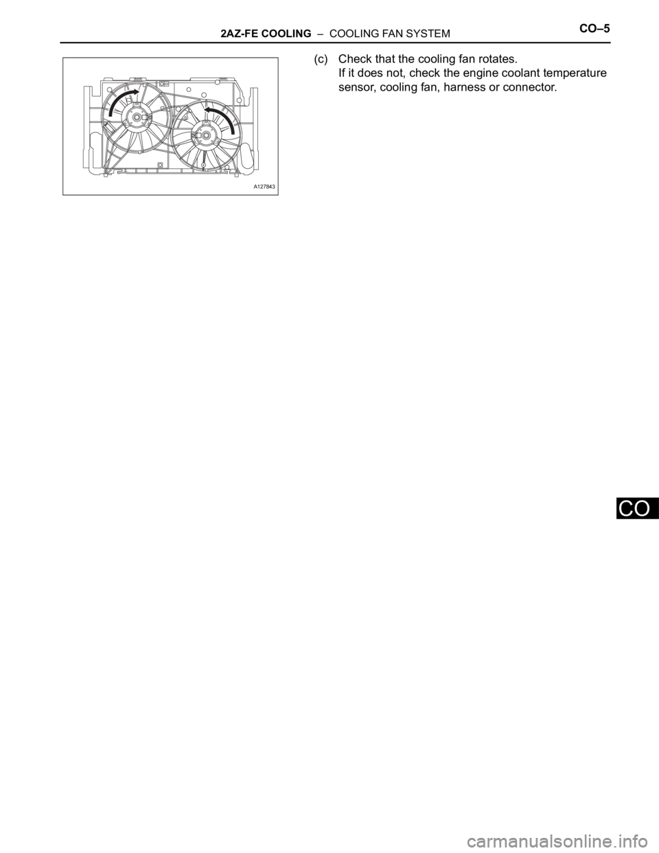
(c) Check that the cooling fan rotates.
If it does not, check the engine coolant temperature
sensor, cooling fan, harness or connector.
A127843
Page 242 of 2000
CO–42GR-FE COOLING – COOLING FAN SYSTEM
CO
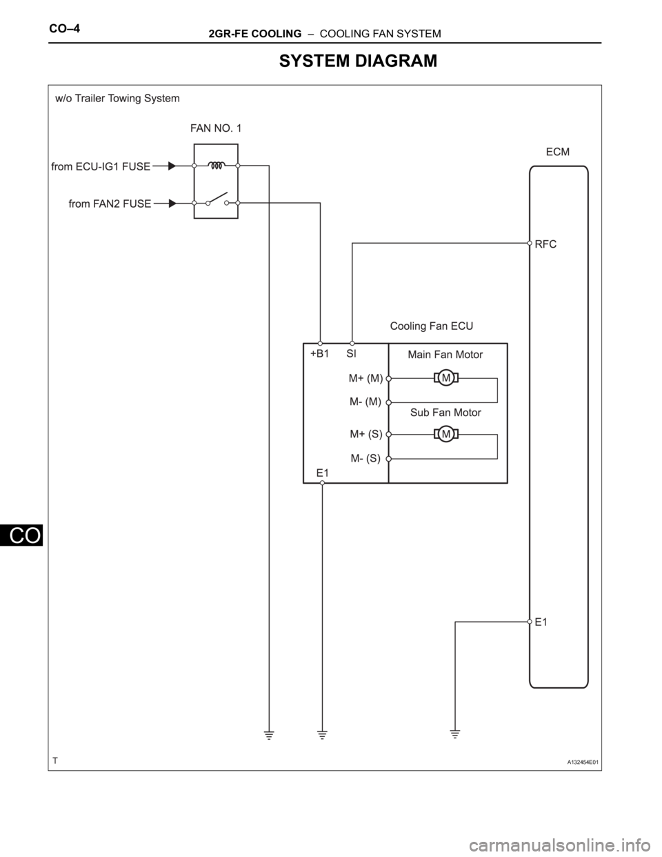
SYSTEM DIAGRAM
A132454E01