lights TOYOTA RAV4 2006 Service User Guide
[x] Cancel search | Manufacturer: TOYOTA, Model Year: 2006, Model line: RAV4, Model: TOYOTA RAV4 2006Pages: 2000, PDF Size: 45.84 MB
Page 1676 of 2000

SUPPLEMENTAL RESTRAINT SYSTEM – AIRBAG SYSTEMRS–27
RS
• The center airbag sensor receives signals
from the deceleration sensor and the
electronic safing sensor built into the center
airbag sensor and the rear airbag sensor, and
determines whether or not the side airbag
and curtain shield airbag should be activated,
and diagnoses system malfunctions.
• The center airbag sensor sends the airbag
deployment signal to ECM through the CAN
to operate the fuel pump control.
(2) Deceleration sensor and ignition control circuit
• The deceleration sensor is built into the
center airbag sensor.
• The ignition control circuit performs
calculations based on the signal output from
the deceleration sensors of the center airbag
sensor and front airbag sensor. If the
calculated values are greater than the
specified values, it activates the deployment
operation.
(3) Safing sensor
The safing sensor is built into the center airbag
sensor. During a frontal collision, the sensor
turns on and outputs an ON signal to the center
airbag sensor if a deceleration rate greater than
the specified value is applied to the safing
sensor.
(4) Electronic safing sensor
The electronic safing sensor is built into the
center airbag sensor. During a side collision, the
sensor turns on and outputs an ON signal to the
center airbag sensor if a deceleration rate
greater than the specified value is applied to the
electronic safing sensor.
(5) Back-up power source
The back-up power source consists of a power
supply capacitor and a DC-DC converter. When
the power system does not function during a
collision, the power supply capacitor discharges
and supplies electric power to the system. The
DC-DC converter operates as a boosting
transformer when the battery voltage falls below
a predetermined level.
(6) Diagnostic circuit
This circuit constantly diagnoses system
malfunctions. When a malfunction is detected, it
lights up the SRS warning light on the telltale
light to inform the driver.
(7) Memory circuit
When a malfunction is detected in the diagnostic
circuit, it is coded and stored in the memory
circuit.
Page 1838 of 2000

LIGHTING – LIGHTING SYSTEMLI–7
LI
SYSTEM DESCRIPTION
1. LIGHTING SYSTEM
(a) Illumination control system (Illuminated entry
system):
When the doors are unlocked by a key or
transmitter operation, or when a door is opened or
closed, the illuminated entry system turns on the
room light, map light, foot light and ignition key
cylinder light*1 or transponder key amplifier*2.
(1) The main body ECU receives the following
signals (A).
• Door courtesy switch signal
• Door detection switch signal
• Ignition switch signal
(2) The main body ECU controls the following signal
based on the signals listed in A.
• Illumination operation signal
(3) The main body ECU controls the on/off and
fade-in/fade-out operation of the following parts.
•Room light
• Map light
•Foot light
• Ignition key cylinder light*1 or transponder
key amplifier*2
HINT:
*1: w/o Engine immobiliser system
*2: w/ Engine immobiliser system
(b) Battery saver system:
When the ignition switch is turned off and any of the
doors is open continuously for 20 minutes, the main
body ECU turns the illumination operation signal off.
As a result, the room light, map light, foot light and
ignition key cylinder lights*1 or transponder key
amplifier*2 turn off.
HINT:
*1: w/o Engine immobiliser system
*2: w/ Engine immobiliser system
(1) The main body ECU receives the following
signals (B).
• Door courtesy switch signal
• Ignition switch signal
(2) The main body ECU controls the following signal
based on the signals listed in B (C).
• Illumination operation signal
(3) The main body ECU controls the illumination
period of the following parts based on the
signals listed in C.
•Room light
• Map light
•Foot light
• Ignition key cylinder light*1 or transponder
key amplifier*2
HINT:
*1: w/o Engine immobiliser system
Page 1839 of 2000

LI–8LIGHTING – LIGHTING SYSTEM
LI
*2: w/ Engine immobiliser system
(c) Manual light control system:
This system functions when lights such as the
headlights and taillights are illuminated by manual
operation of the light control switch.
(1) The main body ECU receives the following
signals (D).
• Light control switch signal
• Headlight dimmer switch signal
• Front fog light switch signal
(2) The main body ECU controls the following
signals based on the signals listed in D (E).
• Headlight relay operation signal
• Taillight relay operation signal
• Daytime running light No. 2 relay operation
signal
• Daytime running light No. 3 relay operation
signal
• Daytime running light No. 4 relay operation
signal
• Front fog light relay operation signal
(3) The main body ECU controls the on/off
operation of the following parts based on the
signals listed in E.
• Headlight (LOW)
• Headlight (HIGH)
• Side marker light (front and rear)
• Front fog light
(d) Light auto turn off system:
When the headlights and taillights are illuminated by
the operation of the light control switch, if the
ignition switch is turned OFF, this system continues
illuminating the headlights and taillights for
approximately 30 seconds, and then turns off the
lights. However, when all the doors are locked
manually, using the door lock button, using the key
or pressing LOCK on the transmitter turns the
headlights and taillights off immediately.
(1) The main body ECU receives the following
signals (F).
• Door courtesy switch signal
• Ignition switch signal
(2) The main body ECU controls the following
signals based on the signals listed in F (G).
• Headlight relay operation signal
• Taillight relay operation signal
• Daytime running light No. 2 relay operation
signal
• Daytime running light No. 3 relay operation
signal
• Daytime running light No. 4 relay operation
signal
• Front fog light relay operation signal
Page 1840 of 2000

LIGHTING – LIGHTING SYSTEMLI–9
LI
(3) The main body ECU controls the illumination
period of the following parts based on the
signals listed in G.
• Headlight (LOW)
• Headlight (HIGH)
• Side marker light (front and rear)
• Front fog light
(e) Daytime running light system:
This system is directly connected to the high-beam
headlights and is designed to automatically activate
the daytime running lights in order to increase the
visibility of the vehicle.
(1) The main body ECU receives the following (H).
• Ignition switch signal
• Engine speed
• Parking brake switch signal
• Light control switch signal
(2) The main body ECU controls the following signal
based on the signals listed in H (I).
• Daytime running light No. 2 relay operation
signal
(3) The main body ECU controls the on/off
operation of the following part based on the
signal listed in I.
• Headlight (HIGH)
Page 1842 of 2000

LIGHTING – LIGHTING SYSTEMLI–11
LI
OPERATION CHECK
1. ILLUMINATED ENTRY SYSTEM OPERATION CHECK
(a) The illuminated entry system controls the following
lights:
• Ignition key cylinder light*1 or transponder key
amplifier*2
• Foot light
• Map light and room light
HINT:
*1: w/o Engine immobiliser system
*2: w/ Engine immobiliser system
(b) Check that the lights come on when unlocking any
of the doors that are closed and locked with the
ignition switch OFF. Then check that the lights fade
out under the following conditions:
(1) Leave the doors unlocked for 15 seconds.
(2) Turn the ignition switch ACC or ON.
(3) Lock all the doors.
(c) Check that the lights stay on for at least 15 seconds
after opening any of the doors before fading out.
Then check that the lights fade out 15 seconds after
closing all the doors.
(d) Check that the lights stay lit after turning the ignition
switch OFF with all the doors closed and the ignition
switch in the ACC or ON position. Then check that
the lights fade out under the following conditions:
(1) Leave the doors unlocked for 15 seconds.
(2) Turn the ignition switch ACC or ON.
(3) Lock all the doors.
(e) Check that the lights stay on for at least 15 seconds
after opening any of the doors. Then check that the
lights fade out 15 seconds after closing all the
doors.
(f) Check that the lights come on when opening any of
the doors and fade out when closing and locking all
the doors or turning the ignition switch to the ACC or
ON position.
2. FOOT LIGHT OPERATION CHECK
(a) Check that the lights come on when unlocking any
of the doors that are closed and locked with the
ignition switch OFF. Then check that the lights fade
out under the following conditions:
(1) Leave the doors unlocked for 15 seconds.
(2) Lock all the closed doors and turn the ignition
switch OFF.
(b) Check that the lights stay on for at least 15 seconds
under the following conditions before going off.
(1) Turn the ignition switch to the ON position, and
move the shift lever to the P position.
(2) Open any of the doors.
(c) Check that the lights dim before going off when
turning the ignition switch ON and shifting the shift
lever into any position other than P.
Page 1843 of 2000

LI–12LIGHTING – LIGHTING SYSTEM
LI
(d) Check the conditions below before the lights go off.
(1) The lights dim when shifting the shift lever into a
position other than P and closing all the doors
with the ignition switch ON.
(2) The lights come on for 15 seconds and fade out
when shifting the shift lever into the P position
and closing all the doors with the ignition switch
OFF.
(e) Check that the lights come on after opening any of
the doors.
(f) Check that the lights fade out 15 seconds after
closing all the doors, or locking all the doors.
(g) Check that the lights come on gradually with the
ignition switch ON and the shift lever in the P
position.
(h) Check that the lights dim when shifting the shift
lever from P into another position with all the doors
closed.
(i) Check that the lights stay dimmed with the ignition
switch ON and the shift lever in a position other than
P.
3. BATTERY SAVER OPERATION CHECK
(a) Turn the ignition switch OFF and close all the doors.
(b) Open any door to turn the room light on, and leave it
open. Check that the light goes off after about 20
minutes.
(c) After the room light goes off, close the driver's door.
(d) Open any door to turn the room light on, and then
open another door. Check that the room light goes
off within 20 minutes after opening the doors.
(e) Close all the doors. Open any door to turn the room
light on. Check that the room light goes off within 20
minutes.
4. LIGHT AUTO TURN OFF OPERATION CHECK
(a) Turn the ignition switch ON, and turn the light
control switch to the TAIL or HEAD position.
(b) Turn the ignition switch OFF and open the driver's
door, and check that the headlights go off after
about 30 seconds.
(c) Turn the ignition switch to the ON position, and turn
the light control switch to the TAIL or HEAD position.
(d) Turn the ignition switch OFF and open the driver's
door. Before the headlight goes off after about 30
seconds, lock all the doors and press the LOCK
switch on the wireless transmitter. Check that the
headlights go off immediately.
5. DAYTIME RUNNING LIGHT OPERATION CHECK
(a) Check that the headlights come on when the light
control switch is off with the engine running and the
parking brake released. Then check that the lights
go off under the following conditions:
(1) Turn the light control switch to the TAIL or HEAD
position.
Page 1844 of 2000

LIGHTING – LIGHTING SYSTEMLI–13
LI
(2) Turn the ignition switch OFF. Check that the
headlights go off immediately.
Page 1857 of 2000
LI–26LIGHTING – LIGHTING SYSTEM
LI
DESCRIPTION
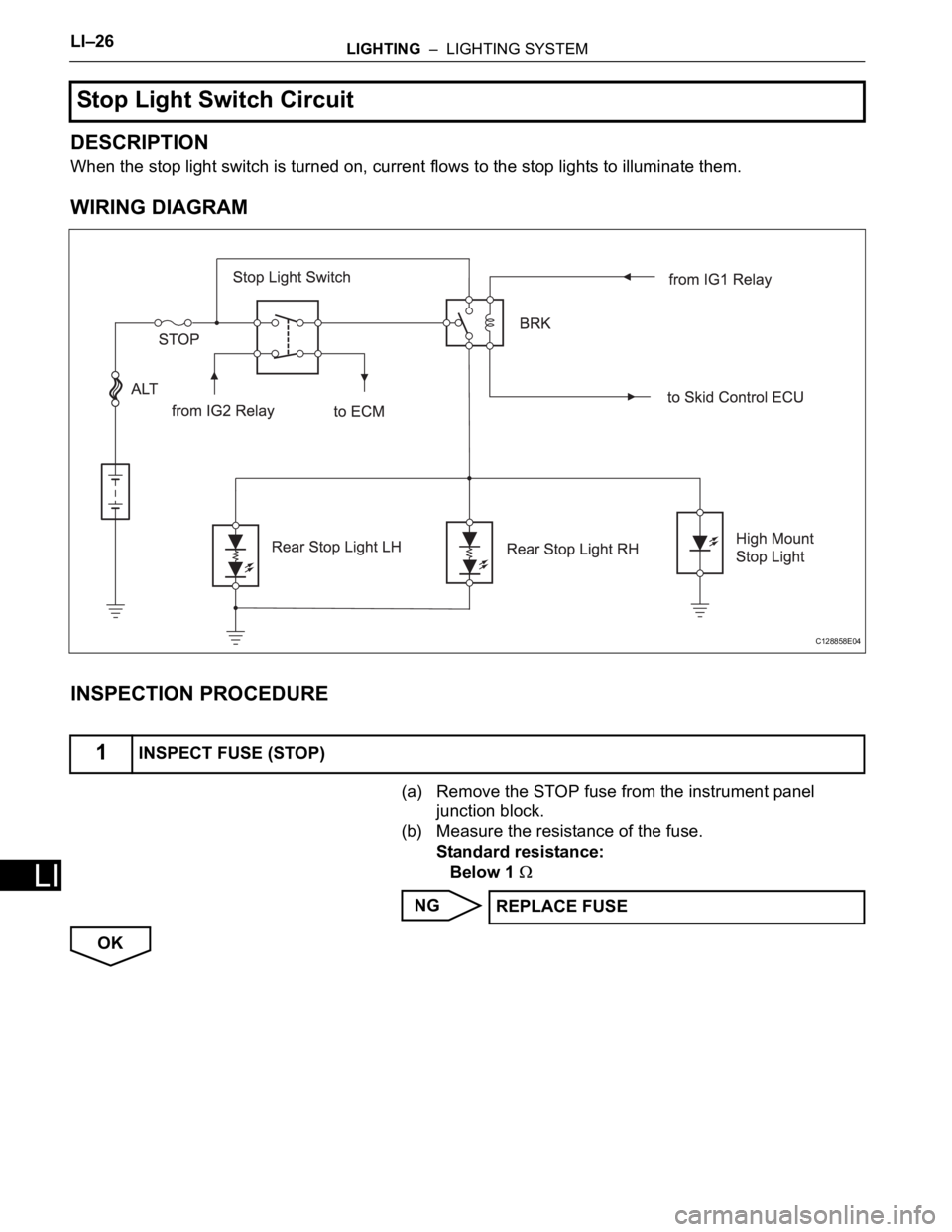
When the stop light switch is turned on, current flows to the stop lights to illuminate them.
WIRING DIAGRAM
INSPECTION PROCEDURE
(a) Remove the STOP fuse from the instrument panel
junction block.
(b) Measure the resistance of the fuse.
Standard resistance:
Below 1
NG
OK
Stop Light Switch Circuit
1INSPECT FUSE (STOP)
C128858E04
REPLACE FUSE
Page 1861 of 2000
LI–30LIGHTING – LIGHTING SYSTEM
LI
DESCRIPTION
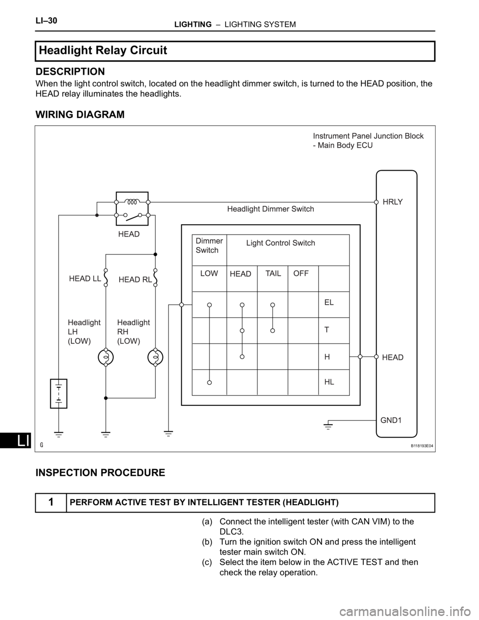
When the light control switch, located on the headlight dimmer switch, is turned to the HEAD position, the
HEAD relay illuminates the headlights.
WIRING DIAGRAM
INSPECTION PROCEDURE
(a) Connect the intelligent tester (with CAN VIM) to the
DLC3.
(b) Turn the ignition switch ON and press the intelligent
tester main switch ON.
(c) Select the item below in the ACTIVE TEST and then
check the relay operation.
Headlight Relay Circuit
1PERFORM ACTIVE TEST BY INTELLIGENT TESTER (HEADLIGHT)
B118193E04
Page 1939 of 2000

2AZ-FE ENGINE CONTROL SYSTEM – SFI SYSTEMES–51
ES
CAT TEMP B1S2Estimated catalyst temperature
(sensor 2):
Min.: -40C, Max.: 6,513.5C--
S O2S B1S2Sub heated oxygen sensor
impedance (sensor2):
Min.: 0
, Max.: 21247.68
--
INI COOL TEMPEngine coolant temperature at
engine start:
Min.: -40
C, Max.: 120CClose to ambient air
temperature-
INI INTAKE TEMPIntake air temperature at engine
start:
Min.: -40
C, Max.: 120CClose to ambient air
temperature-
INJ VOLInjection volume (Cylinder 1):
Min.: 0 ml, Max.: 2.048 ml0 to 0.15 ml: IdlingQuantity of fuel injection volume
for 10 times
STARTER SIGStarter switch (STSW) signal:
ON or OFFON: Cranking -
PS SWPower steering signal:
ON or OFFON: Power steering operation -
PS SIGNALPower steering signal (history):
ON or OFFON: When steering wheel first
turned after battery terminals
connectedSignal status usually ON until
battery terminals disconnected
CTP SWClosed throttle position switch:
ON or OFF• ON: Throttle fully closed
• OFF: Throttle open-
A/C SIGNALA/C signal:
ON or OFFON: A/C ON -
PNP SW [NSW]PNP switch status:
ON or OFFON: P or N position -
ELECT LOAD SIGElectrical load signal:
ON or OFFON: Headlights or defogger
turned ON-
STOP LIGHT SWStop light switch:
ON or OFFON: Brake pedal depressed -
+BMWhether or not electric throttle
control system power inputted:
ON or OFFON: Ignition switch ON and
system normal-
+BM VOLTAGE+BM voltage:
Min.: 0, Max.: 19.9229 to 14 (V): Ignition switch ON
and system normalETCS service data
BATTERY VOLTAGEBattery voltage:
Min.: 0 V, Max.: 65.535 V9 to 14 V: Ignition switch ON -
ACTUATOR POWERActuator power supply:
ON or OFFON: Idling ETCS service data
ATM PRESSUREAtmospheric pressure:
Min.: 0 kPa, Max.: 255 kPaApproximately 100 kPa: Ignition
switch ON-
BATTERY CURRENTBattery current:
Min.: -100 A, Max.: 100 A--
BATTERY TEMPBattery temperature:
Min.: -45
C, Max.: 156.4 F--
ALT OUTPUT DUTYGenerator output duty ratio:
Min.: 0 %, Max.: 100 %- During charge control
ALT V NORMALRequest voltage when regulator
not under forced activation:
Min.: 0 V, Max.: 20 VBattery electrolyte temperature
varies (12.5 to 14.8 V) while
driving:
After engine startAlternator regulator output voltage
is out put
When performing Active Test,
value is 0V
ALT V TSTRequest voltage when regulator
under forced activation:
Min.: 0 V, Max.: 20 VRequest instruction voltage
value:
After engine startCharging control service data
When not performing Active Test,
value is 0V
EVAP (Purge) VSVPurge VSV status:
ON or OFF--
FUEL PUMP / SPDFuel pump status:
ON or OFFON: Engine running Active Test support data Intelligent Tester Display Measurement: Range (Display) Normal Condition*1 Diagnostic Note