check engine TOYOTA RAV4 2006 Service Repair Manual
[x] Cancel search | Manufacturer: TOYOTA, Model Year: 2006, Model line: RAV4, Model: TOYOTA RAV4 2006Pages: 2000, PDF Size: 45.84 MB
Page 1259 of 2000
U241E AUTOMATIC TRANSAXLE – AUTOMATIC TRANSAXLE SYSTEMAX–35
AX
If communication is normal when the tester is connected to
another vehicle, inspect the DLC3 on the original vehicle.
If communication is still not possible when the tester is
connected to another vehicle, the problem is probably in the
tester itself. Consult the Service Department listed in the
tester's instruction manual.
6. CHECK MIL
(a) Check that the MIL illuminates when turning the
ignition switch ON.
If the MIL does not illuminate, there is a problem in
the MIL circuit (see page ES-386).
(b) When the engine is started, the MIL should turn off.
7. ALL READINESS
(a) For this vehicle, using the intelligent tester allows
readiness codes corresponding to all DTCs to be
read. When the diagnosis (normal or
malfunctioning) has been completed, readiness
codes are set. Enter the following menus:
ENHANCED OBD II / MONITOR STATUS.
DTC CHECK / CLEAR
1. CHECK DTC
(a) DTCs which are stored in the ECM can be displayed
with the intelligent tester.
The intelligent tester can display pending DTCs and
current DTCs. Some DTCs are not stored unless a
malfunction is detected in consecutive driving
cycles. When a malfunction is detected in only one
driving cycle, it is stored as a pending DTC.
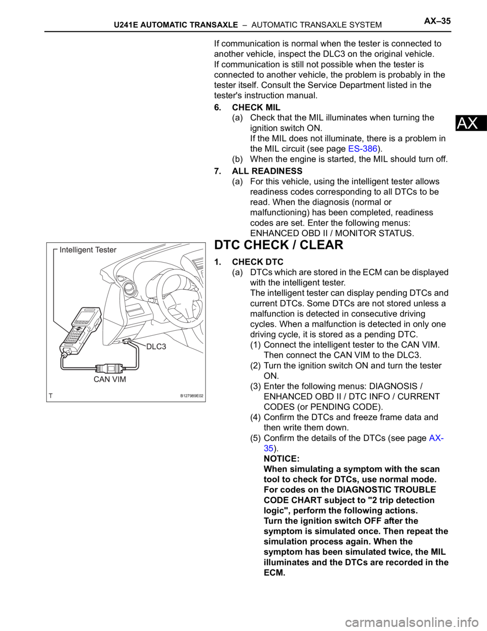
(1) Connect the intelligent tester to the CAN VIM.
Then connect the CAN VIM to the DLC3.
(2) Turn the ignition switch ON and turn the tester
ON.
(3) Enter the following menus: DIAGNOSIS /
ENHANCED OBD II / DTC INFO / CURRENT
CODES (or PENDING CODE).
(4) Confirm the DTCs and freeze frame data and
then write them down.
(5) Confirm the details of the DTCs (see page AX-
35).
NOTICE:
When simulating a symptom with the scan
tool to check for DTCs, use normal mode.
For codes on the DIAGNOSTIC TROUBLE
CODE CHART subject to "2 trip detection
logic", perform the following actions.
Turn the ignition switch OFF after the
symptom is simulated once. Then repeat the
simulation process again. When the
symptom has been simulated twice, the MIL
illuminates and the DTCs are recorded in the
ECM.
B127989E02
Page 1261 of 2000
U241E AUTOMATIC TRANSAXLE – AUTOMATIC TRANSAXLE SYSTEMAX–37
AX
CHECK MODE PROCEDURE
1. DESCRIPTION
(a) Check mode has a higher sensitivity to malfunctions
and can detect malfunctions that normal mode
cannot detect. Check mode can also detect all the
malfunctions that normal mode can detect. In check
mode, DTCs are detected with 1 trip detection logic.
2. CHECK MODE PROCEDURE
(a) Make sure that the following conditions below are
met:
(1) Battery positive voltage 11 V or more
(2) Throttle valve fully closed
(3) Transaxle in the P or N position
(4) A/C OFF
(b) Turn the ignition switch OFF.
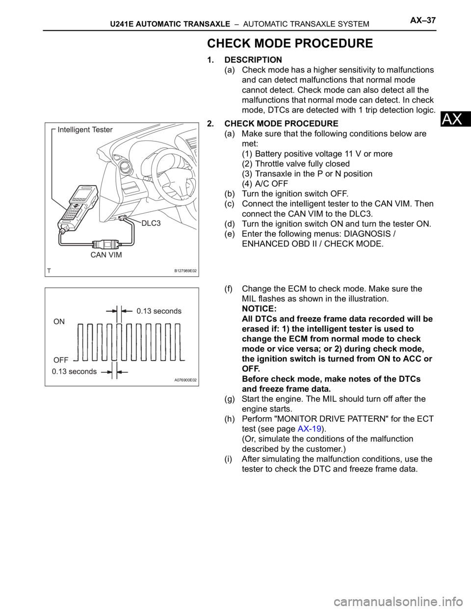
(c) Connect the intelligent tester to the CAN VIM. Then
connect the CAN VIM to the DLC3.
(d) Turn the ignition switch ON and turn the tester ON.
(e) Enter the following menus: DIAGNOSIS /
ENHANCED OBD II / CHECK MODE.
(f) Change the ECM to check mode. Make sure the
MIL flashes as shown in the illustration.
NOTICE:
All DTCs and freeze frame data recorded will be
erased if: 1) the intelligent tester is used to
change the ECM from normal mode to check
mode or vice versa; or 2) during check mode,
the ignition switch is turned from ON to ACC or
OFF.
Before check mode, make notes of the DTCs
and freeze frame data.
(g) Start the engine. The MIL should turn off after the
engine starts.
(h) Perform "MONITOR DRIVE PATTERN" for the ECT
test (see page AX-19).
(Or, simulate the conditions of the malfunction
described by the customer.)
(i) After simulating the malfunction conditions, use the
tester to check the DTC and freeze frame data.
B127989E02
A076900E02
Page 1262 of 2000
U241E AUTOMATIC TRANSAXLE – FLOOR SHIFT ASSEMBLYAX–139
AX
ADJUSTMENT
1. INSPECT SHIFT LEVER POSITION
(a) When shifting the lever from P to the R position with
the ignition switch ON and the brake pedal
depressed, make sure that the shift lever moves
smoothly and moves correctly into position.
(b) Start the engine and make sure that the vehicle
moves forward when shifting the lever from N to the
D position and moves rearward when shifting the
lever to the R position.
If the operation cannot be performed as specified,
inspect the park/neutral position switch assembly
and check the shift lever assembly installation
condition.
2. ADJUST SHIFT LEVER POSITION
(a) Shift the shift lever to the N position
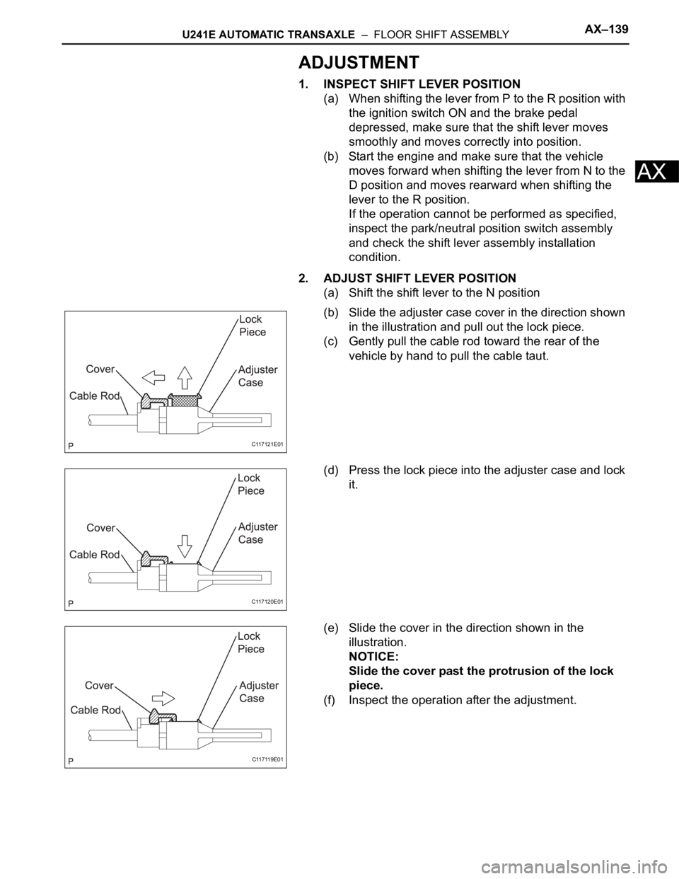
(b) Slide the adjuster case cover in the direction shown
in the illustration and pull out the lock piece.
(c) Gently pull the cable rod toward the rear of the
vehicle by hand to pull the cable taut.
(d) Press the lock piece into the adjuster case and lock
it.
(e) Slide the cover in the direction shown in the
illustration.
NOTICE:
Slide the cover past the protrusion of the lock
piece.
(f) Inspect the operation after the adjustment.
C117121E01
C117120E01
C117119E01
Page 1342 of 2000
TF–14GF1A TRANSFER – ACTIVE TORQUE CONTROL 4WD SYSTEM
TF
NOTICE:
If a part of the 4WD system has a defect, the
4WD indicator light will illuminate.
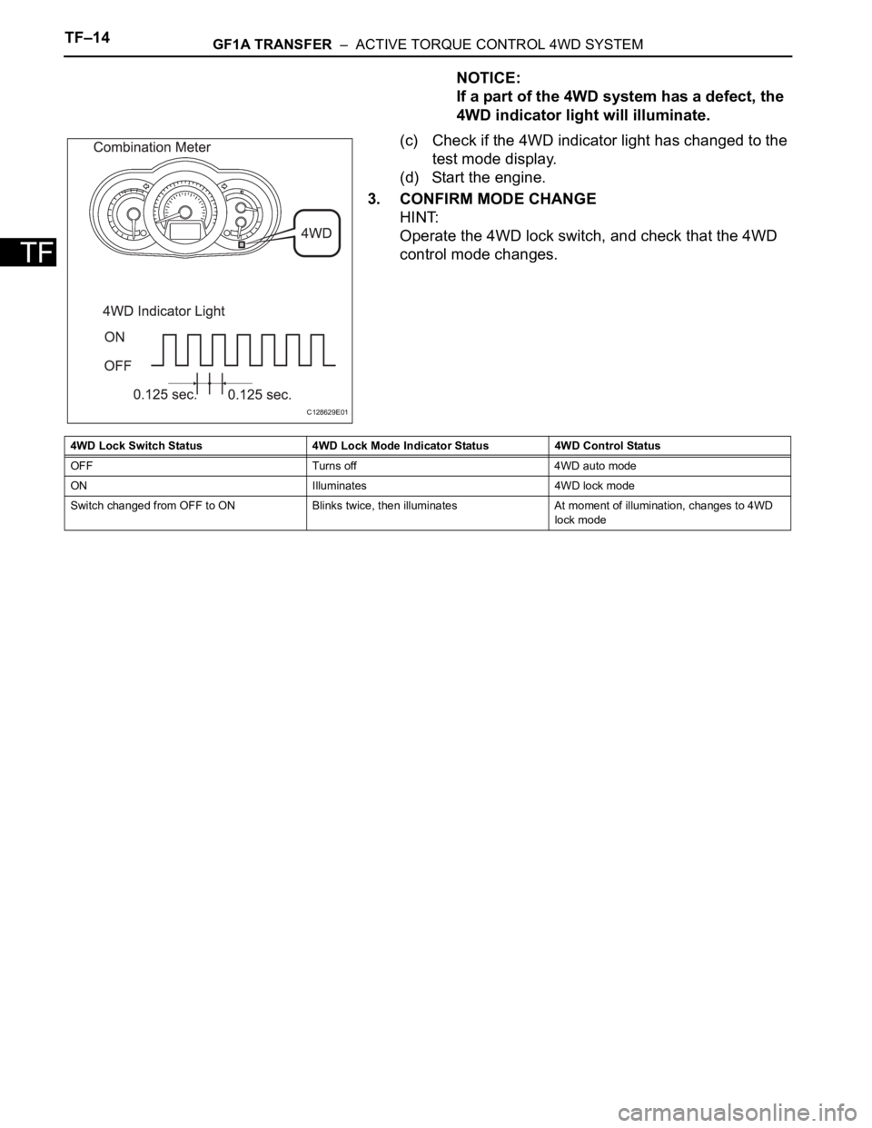
(c) Check if the 4WD indicator light has changed to the
test mode display.
(d) Start the engine.
3. CONFIRM MODE CHANGE
HINT:
Operate the 4WD lock switch, and check that the 4WD
control mode changes.
C128629E01
4WD Lock Switch Status 4WD Lock Mode Indicator Status 4WD Control Status
OFF Turns off 4WD auto mode
ON Illuminates 4WD lock mode
Switch changed from OFF to ON Blinks twice, then illuminates At moment of illumination, changes to 4WD
lock mode
Page 1344 of 2000
TF–16GF1A TRANSFER – ACTIVE TORQUE CONTROL 4WD SYSTEM
TF
TERMINALS OF ECU
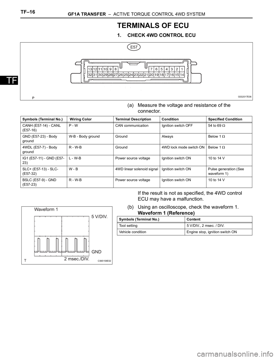
1. CHECK 4WD CONTROL ECU
(a) Measure the voltage and resistance of the
connector.
If the result is not as specified, the 4WD control
ECU may have a malfunction.
(b) Using an oscilloscope, check the waveform 1.
Waveform 1 (Reference)
G032017E06
Symbols (Terminal No.) Wiring Color Terminal Description Condition Specified Condition
CANH (E57-14) - CANL
(E57-16)P - W CAN communication Ignition switch OFF 54 to 69
GND (E57-23) - Body
groundW-B - Body ground Ground Always Below 1
4WDL (E57-7) - Body
groundR - W-B Ground 4WD lock mode switch ON Below 1
IG1 (E57-11) - GND (E57-
23)L - W-B Power source voltage Ignition switch ON 10 to 14 V
SLC+ (E57-13) - SLC-
(E57-32)W - B 4WD linear solenoid signal Ignition switch ON Pulse generation (See
waveform 1)
BSLC (E57-9) - GND
(E57-23)R - W-B Power source voltage Ignition switch ON 10 to 14 V
C065158E02
Symbols (Terminal No.) Content
Tool setting 5 V/DIV., 2 msec. / DIV.
Vehicle condition Engine stop, ignition switch ON
Page 1353 of 2000
GF1A TRANSFER – ACTIVE TORQUE CONTROL 4WD SYSTEMTF–25
TF
(a) Clear the DTC (see page TF-16).
(b) Turn the ignition switch ON and check that no CAN
communication system DTC is output.
(c) Start the engine.
(d) Drive the vehicle, accelerate to a speed of 3 km/h (2
mph) or more, and check that no speed sensor DTC
(brake control system DTC) is output (see page BC-57).
Result
B
C
A
(a) Remove the ECU-IG1 fuse from the instrument junction
block
(b) Measure the resistance of the fuse.
Standard resistance:
Below 1
HINT:
Check for short circuits in all harnesses and connector
connected to the ECU-IG1 fuse (see page IN-5).
NG
OK
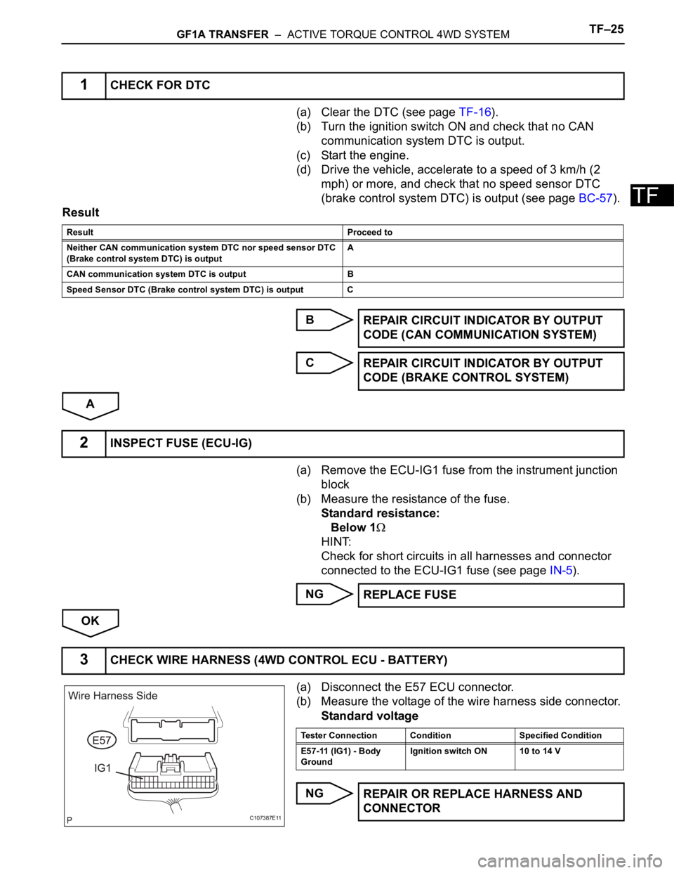
(a) Disconnect the E57 ECU connector.
(b) Measure the voltage of the wire harness side connector.
Standard voltage
NG
1CHECK FOR DTC
Result Proceed to
Neither CAN communication system DTC nor speed sensor DTC
(Brake control system DTC) is outputA
CAN communication system DTC is output B
Speed Sensor DTC (Brake control system DTC) is output C
REPAIR CIRCUIT INDICATOR BY OUTPUT
CODE (CAN COMMUNICATION SYSTEM)
REPAIR CIRCUIT INDICATOR BY OUTPUT
CODE (BRAKE CONTROL SYSTEM)
2INSPECT FUSE (ECU-IG)
REPLACE FUSE
3CHECK WIRE HARNESS (4WD CONTROL ECU - BATTERY)
C107387E11
Tester Connection Condition Specified Condition
E57-11 (IG1) - Body
GroundIgnition switch ON 10 to 14 V
REPAIR OR REPLACE HARNESS AND
CONNECTOR
Page 1354 of 2000
TF–26GF1A TRANSFER – ACTIVE TORQUE CONTROL 4WD SYSTEM
TF
OK
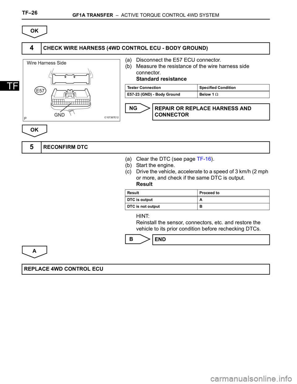
(a) Disconnect the E57 ECU connector.
(b) Measure the resistance of the wire harness side
connector.
Standard resistance
NG
OK
(a) Clear the DTC (see page TF-16).
(b) Start the engine.
(c) Drive the vehicle, accelerate to a speed of 3 km/h (2 mph
or more, and check if the same DTC is output.
Result
HINT:
Reinstall the sensor, connectors, etc. and restore the
vehicle to its prior condition before rechecking DTCs.
B
A
4CHECK WIRE HARNESS (4WD CONTROL ECU - BODY GROUND)
C107387E12
Tester Connection Specified Condition
E57-23 (GND) - Body Ground Below 1
REPAIR OR REPLACE HARNESS AND
CONNECTOR
5RECONFIRM DTC
Result Proceed to
DTC is output A
DTC is not output B
END
REPLACE 4WD CONTROL ECU
Page 1355 of 2000
GF1A TRANSFER – ACTIVE TORQUE CONTROL 4WD SYSTEMTF–27
TF
DESCRIPTION
If a malfunction in the engine control ECU circuit occurs, the 4WD control ECU will output this DTC.
INSPECTION PROCEDURE
HINT:
Check the condition of each related circuit connector before troubleshooting (see page IN-37).
(a) Clear the DTC (see page TF-16).
(b) Turn the ignition switch OFF.
(c) Turn the ignition switch ON and check that can
communication system DTC is not output.
Result
B
A
DTC C1280/82 Engine Circuit Malfunction
DTC No. DTC Detection Condition Trouble Area
C1280/82 When the following continues for 5 seconds
or more:
- Communication with engine control ECU is
operating normally, but throttle position
sensor is malfunctioning.• Throttle position sensor
• Throttle position sensor wire harness and
connector
• CAN communication system
1CHECK FOR DTC
Result Proceed to
CAN communication system DTC is
outputA
Engine control DTC is output B
GO TO ENGINE CONTROL SYSTEM
GO TO CAN COMMUNICATION SYSTEM
Page 1358 of 2000
TF–30GF1A TRANSFER – ACTIVE TORQUE CONTROL 4WD SYSTEM
TF
DESCRIPTION
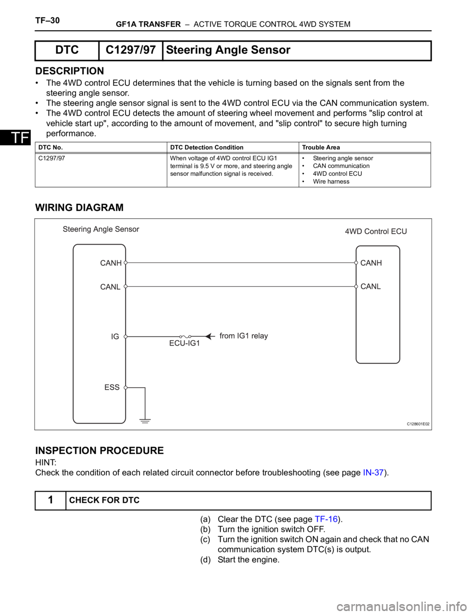
• The 4WD control ECU determines that the vehicle is turning based on the signals sent from the
steering angle sensor.
• The steering angle sensor signal is sent to the 4WD control ECU via the CAN communication system.
• The 4WD control ECU detects the amount of steering wheel movement and performs "slip control at
vehicle start up", according to the amount of movement, and "slip control" to secure high turning
performance.
WIRING DIAGRAM
INSPECTION PROCEDURE
HINT:
Check the condition of each related circuit connector before troubleshooting (see page IN-37).
(a) Clear the DTC (see page TF-16).
(b) Turn the ignition switch OFF.
(c) Turn the ignition switch ON again and check that no CAN
communication system DTC(s) is output.
(d) Start the engine.
DTC C1297/97 Steering Angle Sensor
DTC No. DTC Detection Condition Trouble Area
C1297/97 When voltage of 4WD control ECU IG1
terminal is 9.5 V or more, and steering angle
sensor malfunction signal is received.• Steering angle sensor
• CAN communication
• 4WD control ECU
• Wire harness
1CHECK FOR DTC
C128601E02
Page 1522 of 2000

BRAKE CONTROL – VEHICLE STABILITY CONTROL SYSTEMBC–19
BC
4. FAIL SAFE FUNCTION
(a) When a failure occurs in the ABS with BA, TRC and
VSC systems, the ABS and VSC warning lights
illuminate, the slip indicator light comes on*1 or
remains off*2, and the operations of those systems
are prohibited. In addition to this, when a failure
which disables the EBD operation occurs, the brake
warning light comes on and its operation is
prohibited.
HINT:
*1: for 2WD
*2: for 4WD
(b) If control is prohibited due to a malfunction during
operation, control is disabled gradually to avoid
sudden vehicle instability.
5. INITIAL CHECK
(a) When the vehicle speed first reaches approximately
6 km/h (4 mph) or more after the ignition switch is
turned ON, each solenoid valve and the motor of the
ABS and TRACTION actuator are sequentially
activated to perform electrical checks. During the
initial check, the operating sound of the solenoid
valve and motor can be heard from the engine
compartment, but this does not indicate a
malfunction.
6. SERVICE MODE
(a) VSC operation can be disabled by operating the
intelligent tester.
HINT:
Refer to the intelligent tester operator's manual for
further details.
7. FUNCTION OF COMPONENTS
Components Functions
Speed Sensor
(Semiconductor Type)Detects the wheel speed and sends the signal to skid
control ECU
Skid Control ECU
(Housed in ABS and TRACTION Actuator)• Processes the signals from each sensor to control the
ABS, BA, TRC, and VSC
• Sends and receives control signals to and from the
ECM, yaw rate and deceleration sensor, steering
sensor, etc. via CAN communication.
ABS and TRACTION Actuator • Consists of the master cylinder cut solenoid valve,
holding solenoid valve, pressure reduction solenoid
valve, pump motor, and reservoir, and adjusts the brake
fluid pressure applied to each wheel cylinder
• Houses the skid control ECU
Solenoid Relay • Supplies power to each solenoid
• Housed in the skid control ECU
Motor Relay (VSC MTR Relay) • Supplies power to the pump motor
• Installed in engine room No. 1 relay block
Fail-safe Relay (VSC FAIL Relay) • Cuts off power to the motor when the pump motor circuit
malfunctions
• Installed in engine room No. 1 relay block