check engine TOYOTA RAV4 2006 Service Repair Manual
[x] Cancel search | Manufacturer: TOYOTA, Model Year: 2006, Model line: RAV4, Model: TOYOTA RAV4 2006Pages: 2000, PDF Size: 45.84 MB
Page 1043 of 2000

U151E AUTOMATIC TRANSAXLE – AUTOMATIC TRANSAXLE SYSTEMAX–27
AX
PROBLEM SYMPTOMS TABLE
HINT:
• Use the table below to help determine the cause of the
problem symptom. The potential causes of the symptoms
are listed in order of probability in the "Suspected area"
column of the table. Check each symptom by checking the
suspected areas in the order they are listed. Replace parts
as necessary.
• The Matrix Chart is divided into 2 chapters. When
troubleshooting, check Chapter 1 first. If instructions are
given in Chapter 1 to proceed to 2, proceed as instructed.
• If the instruction "Proceed to next circuit inspection shown
in problem symptoms table" is given in the flowchart for
each circuit, proceed to the next suspected area in the
table.
• If the problem still occurs even though there are no
malfunctions in any of the circuits, check the ECM and
replace it if necessary.
1. Chapter 1: Electronic Circuit Matrix Chart
Symptom Suspected area See page
No down-shift (a particular gear, from 1st to 4th gear, is
not down-shifted)ECMIN-37
No down-shift (5th -> 4th)1. Transmission control switch (4 <--> D position) circuitAX-44
2. Shift solenoid valve S4 circuit*AX-106
3. ECMIN-37
No up-shift (a particular gear, from 1st to 4th gear, is
not up-shifted)ECMIN-37
No up-shift (4th -> 5th)1. Transmission control switch (4 <--> D position) circuitAX-44
2. Shift solenoid valve S4 circuit*AX-106
3. ECMIN-37
No lock-up1. Stop light switch circuit*AX-62
2. Engine coolant temperature sensor circuit*ES-56
3. ECMIN-37
No lock-up off ECMIN-37
Shift point too high or too low1. Throttle position sensor circuit*ES-56
2. ECMIN-37
Up-shift to 5th from 4th while shift lever on 41. Transmission control switch (4 <--> D position) circuitAX-44
2. ECMIN-37
Up-shift to 5th from 4th while engine is cold1. Engine coolant temperature sensor circuit*ES-56
2. ECMIN-37
Up-shift to 2nd from 1st while shift lever is on L1. Transmission control switch (2 <--> L position) circuit*AX-44
2. ECMIN-37
Harsh engagement (N -> D)1. Shift solenoid valve SL1 circuit*AX-76
2. ECMIN-37
Harsh engagement (lock-up) ECMIN-37
Harsh engagement (any driving position) ECMIN-37
Poor acceleration ECMIN-37
No kick-down ECMIN-37
Engine stalls when starting off or stopping ECMIN-37
Malfunction in shifting1. Park/Neutral position switch circuit*AX-44
2. Transmission control switch (4 <--> D position) circuitAX-44
3. ECMIN-37
Page 1048 of 2000
AX–32U151E AUTOMATIC TRANSAXLE – AUTOMATIC TRANSAXLE SYSTEM
AX
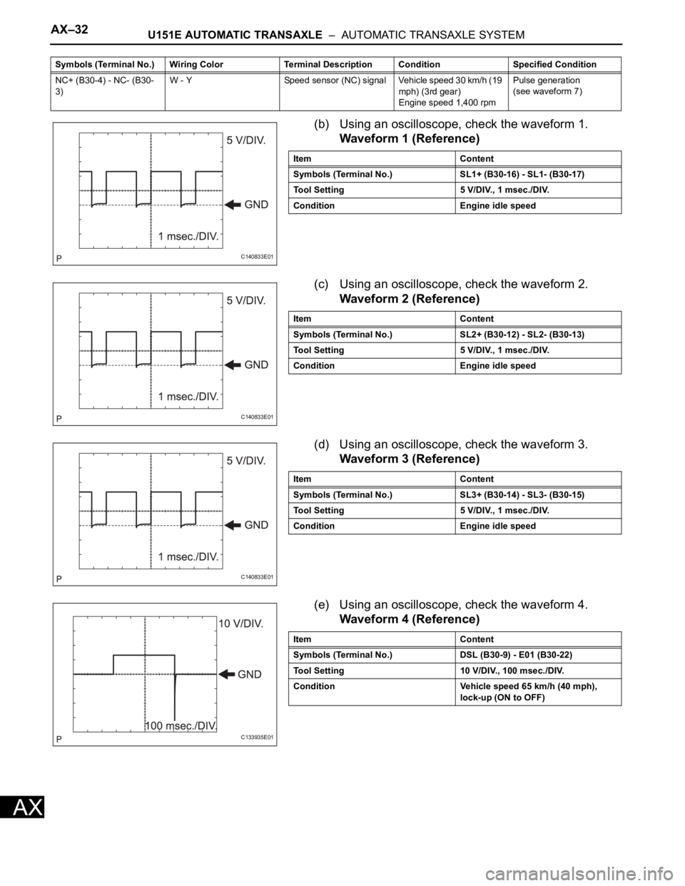
(b) Using an oscilloscope, check the waveform 1.
Waveform 1 (Reference)
(c) Using an oscilloscope, check the waveform 2.
Waveform 2 (Reference)
(d) Using an oscilloscope, check the waveform 3.
Waveform 3 (Reference)
(e) Using an oscilloscope, check the waveform 4.
Waveform 4 (Reference)
NC+ (B30-4) - NC- (B30-
3)W - Y Speed sensor (NC) signal Vehicle speed 30 km/h (19
mph) (3rd gear)
Engine speed 1,400 rpmPulse generation
(see waveform 7) Symbols (Terminal No.) Wiring Color Terminal Description ConditionSpecified Condition
C140833E01
Item Content
Symbols (Terminal No.) SL1+ (B30-16) - SL1- (B30-17)
Tool Setting 5 V/DIV., 1 msec./DIV.
Condition Engine idle speed
C140833E01
Item Content
Symbols (Terminal No.) SL2+ (B30-12) - SL2- (B30-13)
Tool Setting 5 V/DIV., 1 msec./DIV.
Condition Engine idle speed
C140833E01
Item Content
Symbols (Terminal No.) SL3+ (B30-14) - SL3- (B30-15)
Tool Setting 5 V/DIV., 1 msec./DIV.
Condition Engine idle speed
C133935E01
Item Content
Symbols (Terminal No.) DSL (B30-9) - E01 (B30-22)
Tool Setting 10 V/DIV., 100 msec./DIV.
Condition Vehicle speed 65 km/h (40 mph),
lock-up (ON to OFF)
Page 1049 of 2000
U151E AUTOMATIC TRANSAXLE – AUTOMATIC TRANSAXLE SYSTEMAX–33
AX
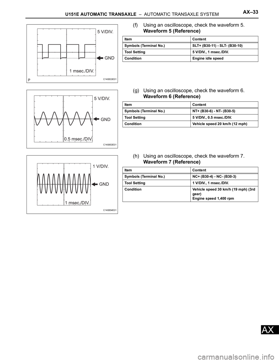
(f) Using an oscilloscope, check the waveform 5.
Waveform 5 (Reference)
(g) Using an oscilloscope, check the waveform 6.
Waveform 6 (Reference)
(h) Using an oscilloscope, check the waveform 7.
Waveform 7 (Reference)
C140833E01
Item Content
Symbols (Terminal No.) SLT+ (B30-11) - SLT- (B30-10)
Tool Setting 5 V/DIV., 1 msec./DIV.
Condition Engine idle speed
C140853E01
Item Content
Symbols (Terminal No.) NT+ (B30-6) - NT- (B30-5)
Tool Setting 5 V/DIV., 0.5 msec./DIV.
Condition Vehicle speed 20 km/h (12 mph)
C140854E01
Item Content
Symbols (Terminal No.) NC+ (B30-4) - NC- (B30-3)
Tool Setting 1 V/DIV., 1 msec./DIV.
Condition Vehicle speed 30 km/h (19 mph) (3rd
gear)
Engine speed 1,400 rpm
Page 1050 of 2000
AX–34U151E AUTOMATIC TRANSAXLE – AUTOMATIC TRANSAXLE SYSTEM
AX
DIAGNOSIS SYSTEM
1. DESCRIPTION
(a) When troubleshooting On-Board Diagnostic (OBD
II) vehicles, the vehicle must be connected to the
OBD II scan tool (complying with SAE J1987).
Various data output from the vehicle's ECM can
then be read.
(b) OBD II regulations require that the vehicle's on-
board computer illuminates the Malfunction
Indicator Lamp (MIL) on the instrument panel when
the computer detects a malfunction in:
(1) The emission control system/components
(2) The powertrain control components (which affect
vehicle emissions)
(3) The computer
In addition, the applicable Diagnostic Trouble
Codes (DTCs) prescribed by SAE J2012 are
recorded in the ECM memory.
When the malfunction does not reoccur, the MIL
stays illuminated until the ignition switch is
turned OFF, and the MIL turns OFF when the
engine is started. However, the DTCs remain
recorded in the ECM memory.
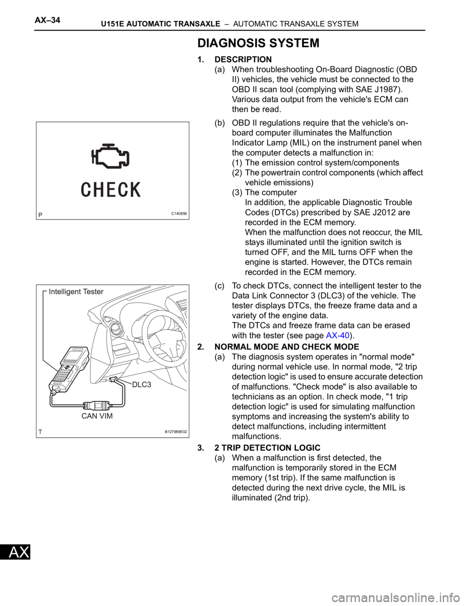
(c) To check DTCs, connect the intelligent tester to the
Data Link Connector 3 (DLC3) of the vehicle. The
tester displays DTCs, the freeze frame data and a
variety of the engine data.
The DTCs and freeze frame data can be erased
with the tester (see page AX-40).
2. NORMAL MODE AND CHECK MODE
(a) The diagnosis system operates in "normal mode"
during normal vehicle use. In normal mode, "2 trip
detection logic" is used to ensure accurate detection
of malfunctions. "Check mode" is also available to
technicians as an option. In check mode, "1 trip
detection logic" is used for simulating malfunction
symptoms and increasing the system's ability to
detect malfunctions, including intermittent
malfunctions.
3. 2 TRIP DETECTION LOGIC
(a) When a malfunction is first detected, the
malfunction is temporarily stored in the ECM
memory (1st trip). If the same malfunction is
detected during the next drive cycle, the MIL is
illuminated (2nd trip).
C140856
B127989E02
Page 1052 of 2000
AX–36U151E AUTOMATIC TRANSAXLE – AUTOMATIC TRANSAXLE SYSTEM
AX
HINT:
Connect the cable of the intelligent tester to the DLC3, turn
the ignition switch ON and attempt to use the tester. If the
screen displays UNABLE TO CONNECT TO VEHICLE, a
problem exists in the vehicle side or the tester side.
If communication is normal when the tester is connected to
another vehicle, inspect the DLC3 on the original vehicle.
If communication is still not possible when the tester is
connected to another vehicle, the problem is probably in the
tester itself. Consult the Service Department listed in the
tester's instruction manual.
6. CHECK MIL
(a) Check that the MIL illuminates when turning the
ignition switch ON.
If the MIL does not illuminate, there is a problem in
the MIL circuit (see page ES-430).
(b) When the engine is started, the MIL should turn off.
7. ALL READINESS
(a) For this vehicle, using the intelligent tester allows
readiness codes corresponding to all DTCs to be
read. When the diagnosis (normal or
malfunctioning) has been completed, readiness
codes are set. Enter the following menus:
ENHANCED OBD II / MONITOR STATUS.
DTC CHECK / CLEAR
1. CHECK DTC
(a) DTCs which are stored in the ECM can be displayed
with the intelligent tester.
The intelligent tester can display pending DTCs and
current DTCs. Some DTCs are not stored unless a
malfunction is detected in consecutive driving
cycles. When a malfunction is detected in only one
driving cycle, it is stored as a pending DTC.
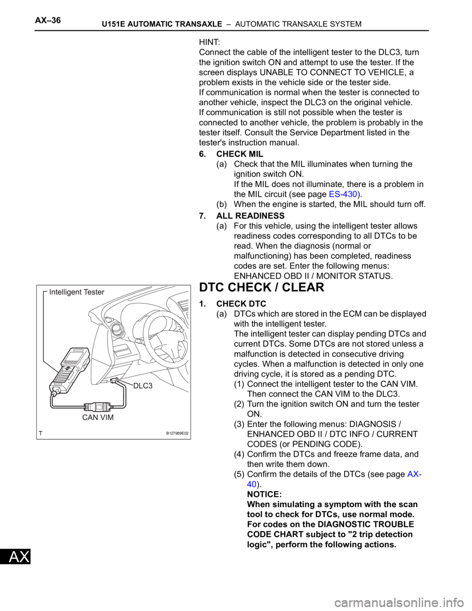
(1) Connect the intelligent tester to the CAN VIM.
Then connect the CAN VIM to the DLC3.
(2) Turn the ignition switch ON and turn the tester
ON.
(3) Enter the following menus: DIAGNOSIS /
ENHANCED OBD II / DTC INFO / CURRENT
CODES (or PENDING CODE).
(4) Confirm the DTCs and freeze frame data, and
then write them down.
(5) Confirm the details of the DTCs (see page AX-
40).
NOTICE:
When simulating a symptom with the scan
tool to check for DTCs, use normal mode.
For codes on the DIAGNOSTIC TROUBLE
CODE CHART subject to "2 trip detection
logic", perform the following actions.
B127989E02
Page 1054 of 2000
AX–38U151E AUTOMATIC TRANSAXLE – AUTOMATIC TRANSAXLE SYSTEM
AX
CHECK MODE PROCEDURE
1. DESCRIPTION
(a) Check mode has a higher sensitivity to malfunctions
and can detect malfunctions that normal mode
cannot detect. Check mode can also detect all the
malfunctions that normal mode can detect. In check
mode, DTCs are detected with 1 trip detection logic.
2. CHECK MODE PROCEDURE
(a) Make sure that the following conditions below are
met:
(1) Battery positive voltage 11 V or more
(2) Throttle valve fully closed
(3) Transaxle in the P or N position
(4) A/C OFF
(b) Turn the ignition switch OFF.
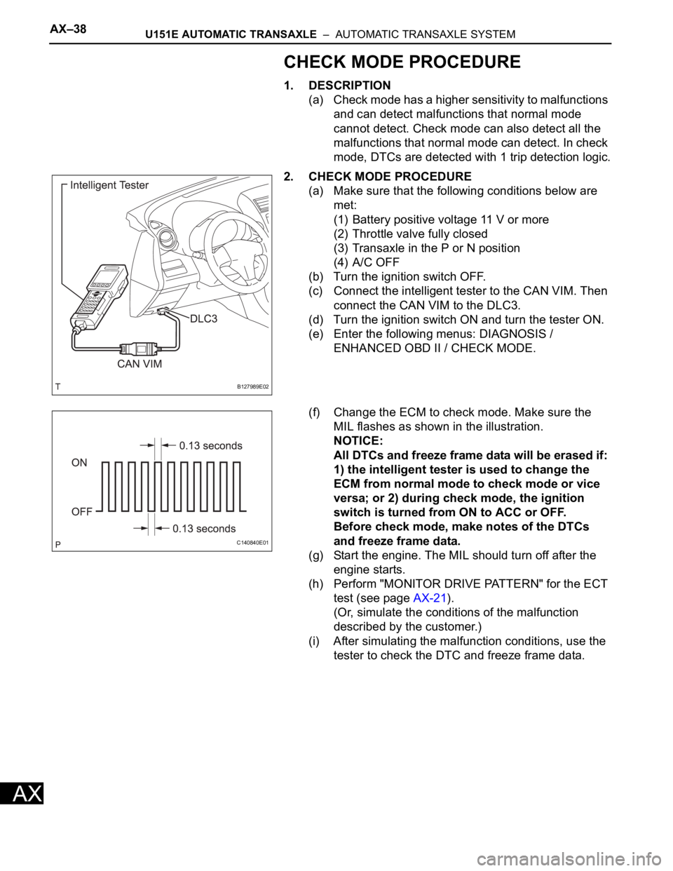
(c) Connect the intelligent tester to the CAN VIM. Then
connect the CAN VIM to the DLC3.
(d) Turn the ignition switch ON and turn the tester ON.
(e) Enter the following menus: DIAGNOSIS /
ENHANCED OBD II / CHECK MODE.
(f) Change the ECM to check mode. Make sure the
MIL flashes as shown in the illustration.
NOTICE:
All DTCs and freeze frame data will be erased if:
1) the intelligent tester is used to change the
ECM from normal mode to check mode or vice
versa; or 2) during check mode, the ignition
switch is turned from ON to ACC or OFF.
Before check mode, make notes of the DTCs
and freeze frame data.
(g) Start the engine. The MIL should turn off after the
engine starts.
(h) Perform "MONITOR DRIVE PATTERN" for the ECT
test (see page AX-21).
(Or, simulate the conditions of the malfunction
described by the customer.)
(i) After simulating the malfunction conditions, use the
tester to check the DTC and freeze frame data.
B127989E02
C140840E01
Page 1055 of 2000
U151E AUTOMATIC TRANSAXLE – FLOOR SHIFT ASSEMBLYAX–165
AX
ADJUSTMENT
1. INSPECT SHIFT LEVER POSITION
(a) When shifting the lever from P to the R position with
the ignition switch ON and the brake pedal
depressed, make sure that the shift lever moves
smoothly and moves correctly into position.
(b) Start the engine and make sure that the vehicle
moves forward when shifting the lever from N to the
D position and moves rearward when shifting the
lever to the R position.
If the operation cannot be performed as specified,
inspect the park/neutral position switch assembly
and check the shift lever assembly installation
condition.
2. ADJUST SHIFT LEVER POSITION
(a) Shift the shift lever to the N position.
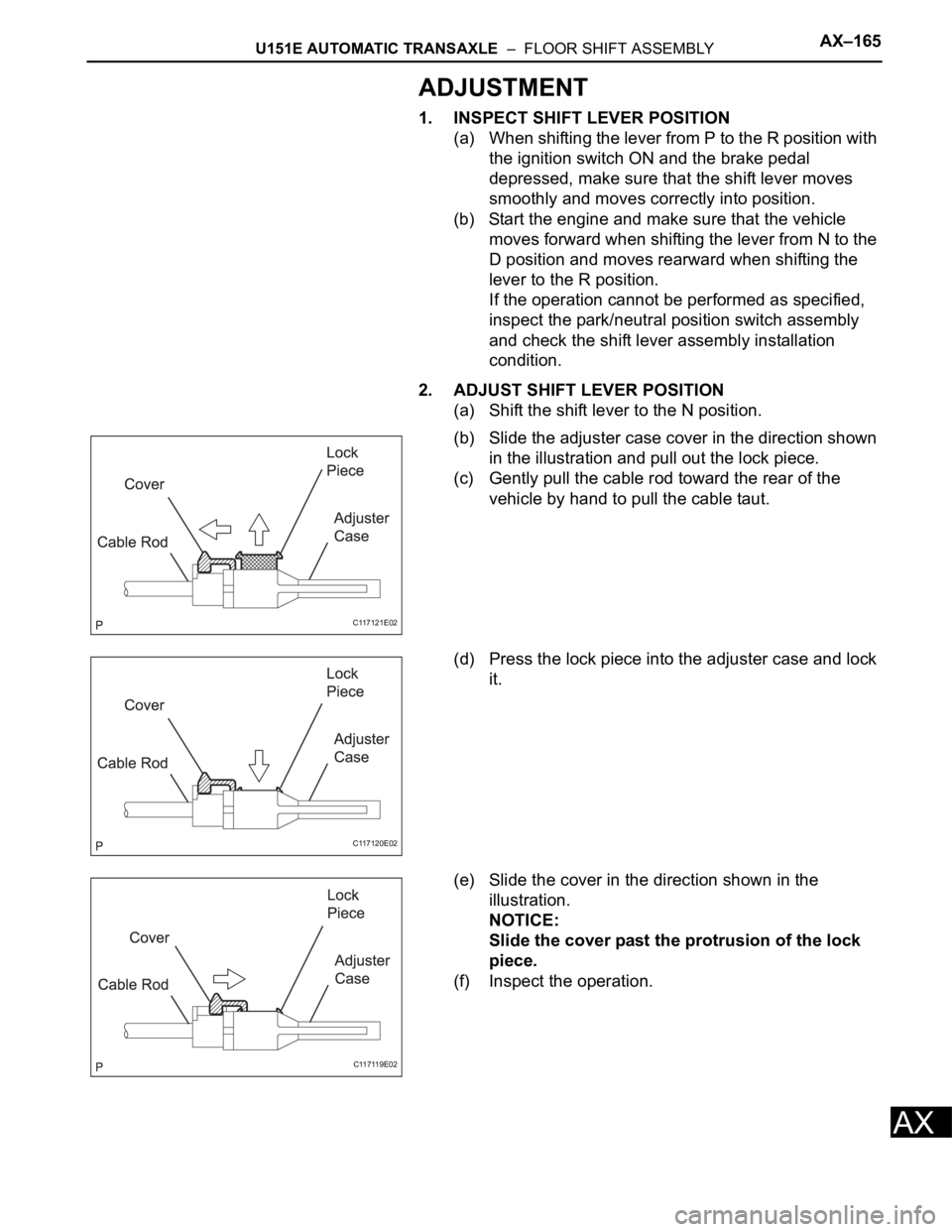
(b) Slide the adjuster case cover in the direction shown
in the illustration and pull out the lock piece.
(c) Gently pull the cable rod toward the rear of the
vehicle by hand to pull the cable taut.
(d) Press the lock piece into the adjuster case and lock
it.
(e) Slide the cover in the direction shown in the
illustration.
NOTICE:
Slide the cover past the protrusion of the lock
piece.
(f) Inspect the operation.
C117121E02
C117120E02
C117119E02
Page 1134 of 2000

U151F AUTOMATIC TRANSAXLE – AUTOMATIC TRANSAXLE SYSTEMAX–15
AX
ROAD TEST
1. PROBLEM SYMPTOM CONFIRMATION
(a) Based on the result of the customer problem
analysis, try to reproduce the symptoms. If the
problem is that the transaxle does not shift up, shift
down, or the shift point is too high or too low,
conduct the following road test referring to the
automatic shift schedule and simulate the problem
symptoms.
2. ROAD TEST
NOTICE:
Perform the test at the normal operating ATF
temperature of 50 to 80
C (122 to 176F).
(a) D position test:
Move the shift lever to D and fully depress the
accelerator pedal. Check the following:
(1) Check up-shift operation.
Check that the 1
2, 2 3, 3 4 and 4 5th
up-shifts take place at the shift point shown in
the automatic shift schedule (see page SS-49).
HINT:
5th Gear Up-shift Prohibition Control
• Engine coolant temperature is 55
C (131F)
or less and vehicle speed is at 80 km/h (50
mph) or less.
• ATF temperature is -2
C (28F) or less.
4th Gear Up-shift Prohibition Control
• Engine coolant temperature is 47
C (117F)
or less and vehicle speed is at 55 km/h (34
mph) or less.
5th and 4th Gear Lock-up Prohibition Control
• Brake pedal is depressed.
• Accelerator pedal is released.
• Engine coolant temperature is 60
C (140F)
or less.
(2) Check for shift shock and slip.
Check for shock and slip at the 1
2, 2 3, 3
4 and 4 5th up-shifts.
(3) Check for abnormal noise and vibration.
Check for abnormal noise and vibration when
up-shifting from 1
2, 2 3, 3 4 and 4
5th while driving with the shift lever on D, and
check while driving in the lock-up condition.
HINT:
The check for the cause of abnormal noise and
vibration must be done thoroughly as it could
also be due to loss of balance in the differential,
torque converter clutch, etc.
Page 1135 of 2000

AX–16U151F AUTOMATIC TRANSAXLE – AUTOMATIC TRANSAXLE SYSTEM
AX
(4) Check kick-down operation.
While driving the vehicle in the 2nd, 3rd, 4th and
5th gears with the shift lever on D, check that the
possible kick-down vehicle speed limits for 2
1, 3
2, 4 3 and 5 4 kick-downs conform
to those indicated in the automatic shift schedule
(see page SS-49).
(5) Check for abnormal shock and slip at kick-down.
(6) Check the lock-up mechanism.
• Drive the vehicle in the 5th gear with the shift
lever on D. Maintain a steady speed (lock-up
ON).
• Lightly depress the accelerator pedal and
check that the engine speed does not change
abruptly.
HINT:
• There is no lock-up in the 1st, 2nd and 3rd
gear.
• 4th lock-up operates while uphill-downhill
control is active with the shift lever on D.
• If there is a sudden increase in engine speed,
there is no lock-up.
(b) 4 (O/D OFF) position test:
Move the shift lever to 4 and fully depress the
accelerator pedal. Check the following:
(1) Check up-shift operation.
Check that the 1
2, 2 3 and 3 4 up-shifts
take place and that the shift point conforms to
the automatic shift schedule (see page SS-49).
HINT:
There is no 5th up-shift in the 4 position.
(2) Check engine braking.
While driving the vehicle in the 4th gear with the
shift lever on 4, release the accelerator pedal
and check the engine braking effect.
(3) Check for abnormal noise during acceleration
and deceleration, and for shock at up-shift and
down-shift.
(c) 3 position test:
Move the shift lever to 3 and fully depress the
accelerator pedal. Check the following:
(1) Check up-shift operation.
Check that the 1
2 and 2 3 up-shifts take
place and that the shift point conforms to the
automatic shift schedule (see page SS-49).
HINT:
There is no 3rd up-shift and lock-up in the 3
position.
(2) Check engine braking.
While driving the vehicle in the 3rd gear with the
shift lever on 3, release the accelerator pedal
and check the engine braking effect.
Page 1136 of 2000

U151F AUTOMATIC TRANSAXLE – AUTOMATIC TRANSAXLE SYSTEMAX–17
AX
(3) Check for abnormal noise during acceleration
and deceleration, and for shock at up-shift and
down-shift.
(d) 2 position test:
Move the shift lever to 2 and fully depress the
accelerator pedal. Check the following:
(1) Check up-shift operation.
Check that the 1
2 up-shifts take place and
that the shift point conforms to the automatic
shift schedule (see page SS-49).
HINT:
There is no 3rd up-shift and lock-up when the
shift lever is on 2.
(2) Check engine braking.
While driving the vehicle in the 2nd gear with the
shift lever on 2, release the accelerator pedal
and check the engine braking effect.
(3) Check for abnormal noise during acceleration
and deceleration, and for shock at up-shift and
down-shift.
(e) L position test:
Move the shift lever to L and fully depress the
accelerator pedal. Check the following:
(1) Check no up-shift.
While driving the vehicle with the shift lever on L,
check that there is no up-shift to 2nd gear.
HINT:
There is no lock-up in L.
(2) Check engine braking.
While driving the vehicle with the shift lever on L,
release the accelerator pedal and check the
engine braking effect.
(3) Check for abnormal noises during acceleration
and deceleration.
(f) R position test:
Move the shift lever to R and lightly depress the
accelerator pedal. Check that the vehicle moves
backward without any abnormal noise or vibration.
CAUTION:
Before conducting this test, ensure that no
people or obstacles are in the test area.
(g) P position test:
Stop the vehicle on an incline (more than 5
). Then
move the shift lever to P and release the parking
brake. Check that the parking lock pawl holds the
vehicle in place.
(h) Uphill/downhill control function test:
(1) Check that the gear does not up-shift to the 4th
or 5th gear while the vehicle is driving uphill.
(2) Check that the gear automatically down-shifts
from 5
4 or from 4 3 when the brake is
applied while the vehicle is driving downhill.