sensor TOYOTA RAV4 2006 Service Repair Manual
[x] Cancel search | Manufacturer: TOYOTA, Model Year: 2006, Model line: RAV4, Model: TOYOTA RAV4 2006Pages: 2000, PDF Size: 45.84 MB
Page 1702 of 2000
SUPPLEMENTAL RESTRAINT SYSTEM – AIRBAG SYSTEMRS–53
RS
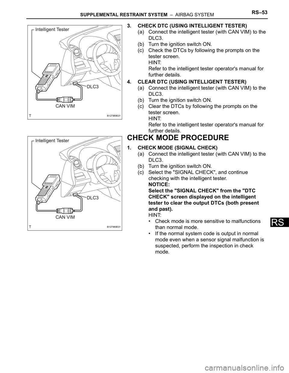
3. CHECK DTC (USING INTELLIGENT TESTER)
(a) Connect the intelligent tester (with CAN VIM) to the
DLC3.
(b) Turn the ignition switch ON.
(c) Check the DTCs by following the prompts on the
tester screen.
HINT:
Refer to the intelligent tester operator's manual for
further details.
4. CLEAR DTC (USING INTELLIGENT TESTER)
(a) Connect the intelligent tester (with CAN VIM) to the
DLC3.
(b) Turn the ignition switch ON.
(c) Clear the DTCs by following the prompts on the
tester screen.
HINT:
Refer to the intelligent tester operator's manual for
further details.
CHECK MODE PROCEDURE
1. CHECK MODE (SIGNAL CHECK)
(a) Connect the intelligent tester (with CAN VIM) to the
DLC3.
(b) Turn the ignition switch ON.
(c) Select the "SIGNAL CHECK", and continue
checking with the intelligent tester.
NOTICE:
Select the "SIGNAL CHECK" from the "DTC
CHECK" screen displayed on the intelligent
tester to clear the output DTCs (both present
and past).
HINT:
• Check mode is more sensitive to malfunctions
than normal mode.
• If the normal system code is output in normal
mode even when a sensor signal malfunction is
suspected, perform the inspection in check
mode.
B127989E01
B127989E01
Page 1703 of 2000

RS–54SUPPLEMENTAL RESTRAINT SYSTEM – AIRBAG SYSTEM
RS
DATA LIST / ACTIVE TEST
1. READ DATA LIST
HINT:
Using the intelligent tester's Data List allows switch,
sensor, actuator and other item values to be read without
removing any parts. Reading the Data List early in
troubleshooting in one way to save time.
(a) Connect the intelligent tester (with CAN VIM) to the
DLC3.
(b) Turn the ignition switch ON.
(c) Read the Data List according to the display on the
tester.
Center airbag sensor
Item Measure Item / Range (Display) Normal Condition Diagnostic Note
D SEAT POSITIONSeat position (Driver side)/
FORWARD: Seat position
forward
BKWARD: Seat position
backward
FAIL: Failure detectedFORWARD/BKWARD -
PASSENGER CLASSFront passenger classification/
NG: Data is not determined
OFF: Vacant
CHILD: Child (Less than 36 kg
[79.37 lb]) seated
AF05: Adult (36 to 54 kg [79.37 to
119.05 lb]) seated
AM50: Adult (More than 54 kg
[119.05 lb]) seated
FAIL: Failure detectedNG/OFF/CHILD/AF05/AM50/FAIL -
D BUCKLE SWBuckle switch (Driver side)/
UNSET: Seat belt not fastened
SET: Seat belt fastened
NG: Data not determinedUNSET/SET -
P BUCKLE SWBuckle switch (Front passenger
side)/
UNSET: Seat belt not fastened
SET: Seat belt fastened
NG: Data not determinedUNSET/SET -
DISPLAY TYPEDisplay type identification
information/
LR: Display indicated by LH/RH
DP: Display indicated by Driver/
PassengerDP -
PAST CODESNumber of past DTCs / Min.: 0,
Max.: 2550-
Page 1704 of 2000

SUPPLEMENTAL RESTRAINT SYSTEM – AIRBAG SYSTEMRS–55
RS
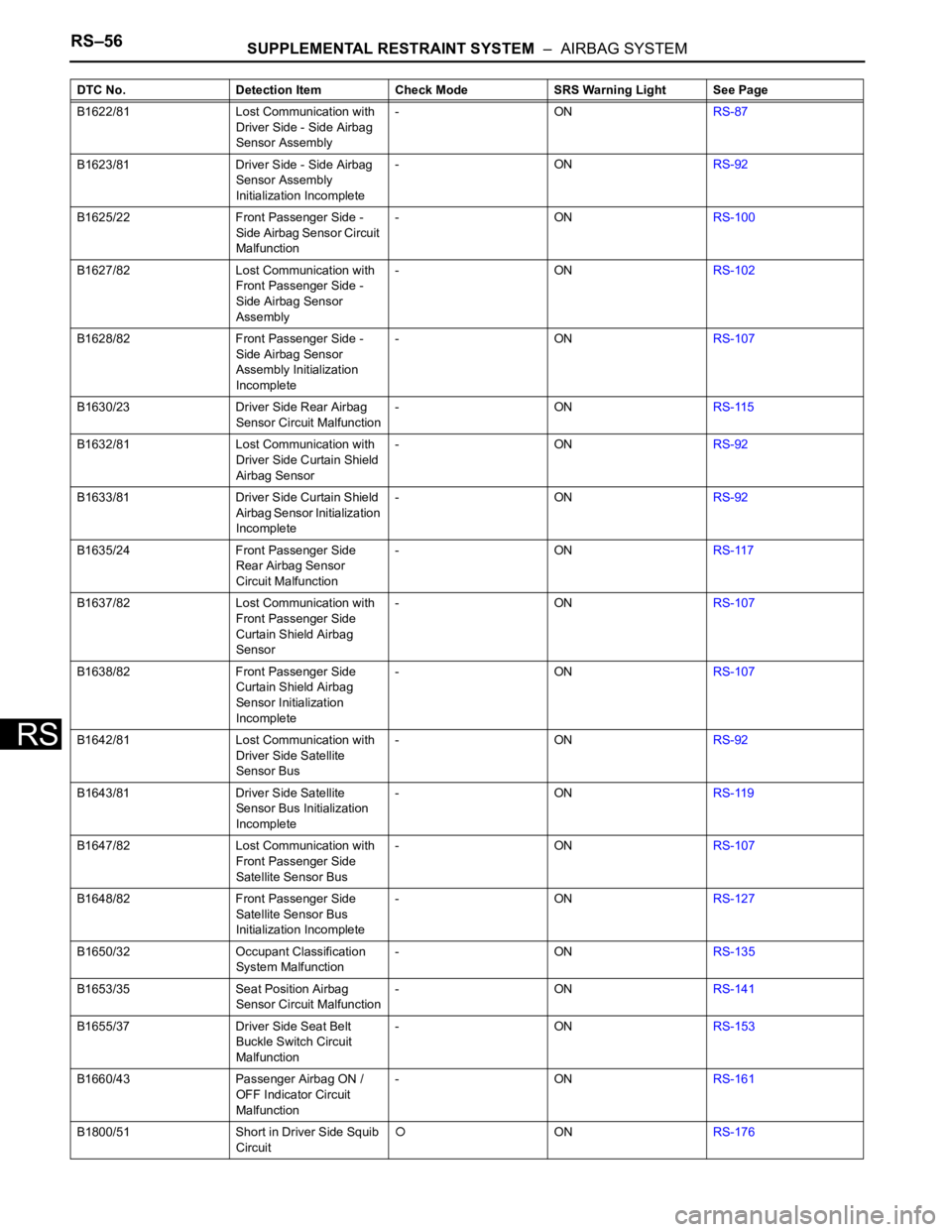
DIAGNOSTIC TROUBLE CODE CHART
If a DTC is displayed during the DTC check, check the circuit
listed for the DTC in the table below (refer to the appropriate
page).
HINT:
• When the SRS warning light remains on and the normal
system code is output, a decrease in the source voltage is
likely to occur. This malfunction is not stored in the
memory of the center airbag sensor. If the power source
voltage returns to normal, the SRS warning light will
automatically go off.
• When 2 or more DTCs are indicated, the DTC with the
lowest number appears first.
• If a DTC is not listed on the DTC chart, the center airbag
sensor may have malfunctioned.
• In the case of any malfunctions concerning open circuits,
shorts to ground, or shorts to B+ due to squibs, other
DTCs may not be set. In this case, repair the malfunction
currently indicated and then perform a malfunction
diagnosis again.
• Mark in the check mode column:
-: DTC does not correspond to check mode.
: DTC corresponds to check mode.
• When DTC B1650/32 is set as a result of troubleshooting
the Supplemental Restraint System (SRS), perform
troubleshooting for the occupant classification system.
Airbag System
DTC No. Detection Item Check Mode SRS Warning Light See Page
B1000/31 Center Airbag Sensor
Assembly Malfunction-ONRS-58
B1602/83 Lost Communication with
Front Satellite Sensor Bus
RH-ONRS-59
B1603/83 Front Satellite Sensor Bus
RH Initialization
Incomplete-ONRS-59
B1607/84 Lost Communication with
Front Satellite Sensor Bus
LH-ONRS-70
B1608/84 Front Satellite Sensor Bus
LH Initialization
Incomplete-ONRS-70
B1610/13 Front Airbag Sensor RH
Circuit Malfunction-ONRS-81
B1612/83 Lost Communication with
Front Airbag Sensor RH-ONRS-59
B1613/83 Front Airbag Sensor RH
Initialization Incomplete-ONRS-59
B1615/14 Front Airbag Sensor LH
Circuit Malfunction-ONRS-83
B1617/84 Lost Communication with
Front Airbag Sensor LH-ONRS-70
B1618/84 Front Airbag Sensor LH
Initialization Incomplete-ONRS-70
B1620/21 Driver Side - Side Airbag
Sensor Circuit Malfunction-ONRS-85
Page 1705 of 2000
RS–56SUPPLEMENTAL RESTRAINT SYSTEM – AIRBAG SYSTEM
RS
B1622/81 Lost Communication with
Driver Side - Side Airbag
Sensor Assembly-ONRS-87
B1623/81 Driver Side - Side Airbag
Sensor Assembly
Initialization Incomplete-ONRS-92
B1625/22 Front Passenger Side -
Side Airbag Sensor Circuit
Malfunction-ONRS-100
B1627/82 Lost Communication with
Front Passenger Side -
Side Airbag Sensor
Assembly-ONRS-102
B1628/82 Front Passenger Side -
Side Airbag Sensor
Assembly Initialization
Incomplete-ONRS-107
B1630/23 Driver Side Rear Airbag
Sensor Circuit Malfunction-ONRS-115
B1632/81 Lost Communication with
Driver Side Curtain Shield
Airbag Sensor-ONRS-92
B1633/81 Driver Side Curtain Shield
Airbag Sensor Initialization
Incomplete-ONRS-92
B1635/24 Front Passenger Side
Rear Airbag Sensor
Circuit Malfunction-ONRS-117
B1637/82 Lost Communication with
Front Passenger Side
Curtain Shield Airbag
Sensor-ONRS-107
B1638/82 Front Passenger Side
Curtain Shield Airbag
Sensor Initialization
Incomplete-ONRS-107
B1642/81 Lost Communication with
Driver Side Satellite
Sensor Bus-ONRS-92
B1643/81 Driver Side Satellite
Sensor Bus Initialization
Incomplete-ONRS-119
B1647/82 Lost Communication with
Front Passenger Side
Satellite Sensor Bus-ONRS-107
B1648/82 Front Passenger Side
Satellite Sensor Bus
Initialization Incomplete-ONRS-127
B1650/32 Occupant Classification
System Malfunction-ONRS-135
B1653/35 Seat Position Airbag
Sensor Circuit Malfunction-ONRS-141
B1655/37 Driver Side Seat Belt
Buckle Switch Circuit
Malfunction-ONRS-153
B1660/43 Passenger Airbag ON /
OFF Indicator Circuit
Malfunction-ONRS-161
B1800/51 Short in Driver Side Squib
Circuit
ONRS-176 DTC No. Detection Item Check Mode SRS Warning Light See Page
Page 1708 of 2000
SUPPLEMENTAL RESTRAINT SYSTEM – AIRBAG SYSTEMRS–59
RS
DESCRIPTION
The center airbag sensor consists of the airbag sensor, the safing sensor, the drive circuit, the diagnosis
circuit and the ignition control.
If the center airbag sensor receives signals from the airbag sensor, it determines whether or not the SRS
should be activated.
DTC B1000/31 is recorded when a malfunction is detected in the center airbag sensor.
HINT:
When a malfunction code is displayed simultaneously with DTC B1000/31, repair the malfunction
indicated by this code (except DTC B1000/31) first.
INSPECTION PROCEDURE
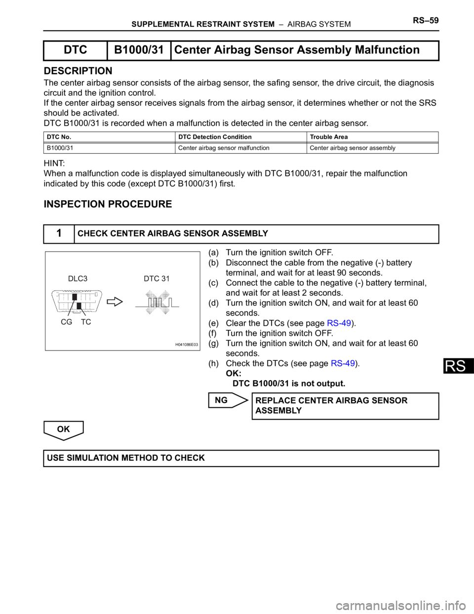
(a) Turn the ignition switch OFF.
(b) Disconnect the cable from the negative (-) battery
terminal, and wait for at least 90 seconds.
(c) Connect the cable to the negative (-) battery terminal,
and wait for at least 2 seconds.
(d) Turn the ignition switch ON, and wait for at least 60
seconds.
(e) Clear the DTCs (see page RS-49).
(f) Turn the ignition switch OFF.
(g) Turn the ignition switch ON, and wait for at least 60
seconds.
(h) Check the DTCs (see page RS-49).
OK:
DTC B1000/31 is not output.
NG
OK
DTC B1000/31 Center Airbag Sensor Assembly Malfunction
DTC No. DTC Detection Condition Trouble Area
B1000/31 Center airbag sensor malfunction Center airbag sensor assembly
1CHECK CENTER AIRBAG SENSOR ASSEMBLY
H041086E03
REPLACE CENTER AIRBAG SENSOR
ASSEMBLY
USE SIMULATION METHOD TO CHECK
Page 1709 of 2000

RS–60SUPPLEMENTAL RESTRAINT SYSTEM – AIRBAG SYSTEM
RS
DESCRIPTION
The front airbag sensor RH consists of the diagnostic circuit and the frontal deceleration sensor.
If the center airbag sensor receives signals from the frontal deceleration sensor, it determines whether or
not the SRS should be activated.
DTC B1602/83, B1603/83, B1612/83 or B1613/83 is recorded when a malfunction is detected in the front
airbag sensor RH circuit.
DTC B1602/83Lost Communication with Front Satellite Sen-
sor Bus RH
DTC B1603/83Front Satellite Sensor Bus RH Initialization
Incomplete
DTC B1612/83Lost Communication with Front Airbag Sensor
RH
DTC B1613/83Front Airbag Sensor RH Initialization Incom-
plete
DTC No. DTC Detection Condition Trouble Area
B1602/83
B1603/83
B1612/83
B1613/83When one of following conditions is met:
• Center airbag sensor detects line short
signal, open signal, short to ground signal
or short to B+ signal in the front airbag
sensor RH circuit for 2 seconds.
• Front airbag sensor RH malfunction
• Center airbag sensor malfunction• Instrument panel wire
• Engine room main wire
• Front airbag sensor RH
• Center airbag sensor
Page 1710 of 2000
SUPPLEMENTAL RESTRAINT SYSTEM – AIRBAG SYSTEMRS–61
RS
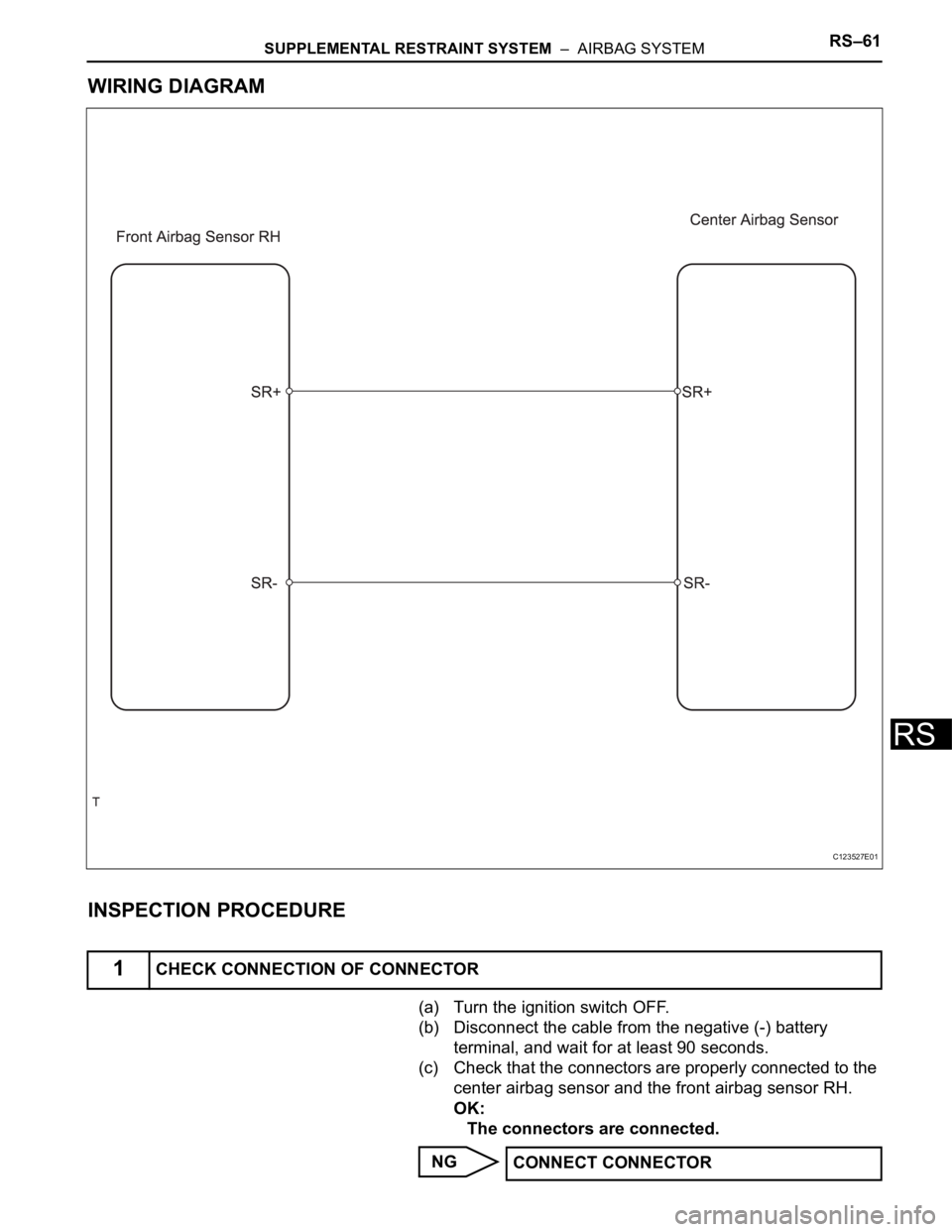
WIRING DIAGRAM
INSPECTION PROCEDURE
(a) Turn the ignition switch OFF.
(b) Disconnect the cable from the negative (-) battery
terminal, and wait for at least 90 seconds.
(c) Check that the connectors are properly connected to the
center airbag sensor and the front airbag sensor RH.
OK:
The connectors are connected.
NG
1CHECK CONNECTION OF CONNECTOR
C123527E01
CONNECT CONNECTOR
Page 1711 of 2000
RS–62SUPPLEMENTAL RESTRAINT SYSTEM – AIRBAG SYSTEM
RS
OK
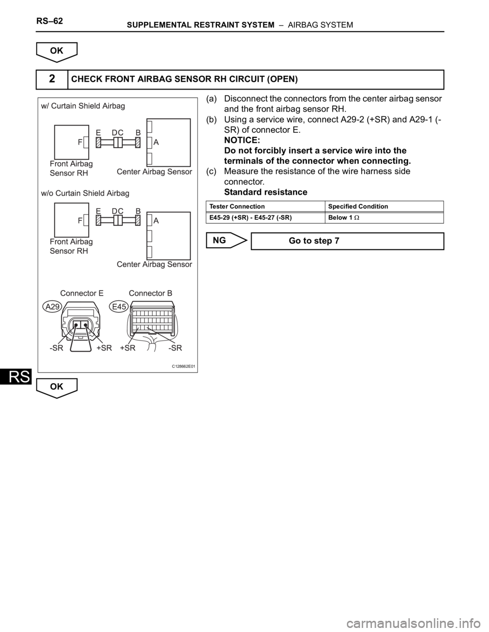
(a) Disconnect the connectors from the center airbag sensor
and the front airbag sensor RH.
(b) Using a service wire, connect A29-2 (+SR) and A29-1 (-
SR) of connector E.
NOTICE:
Do not forcibly insert a service wire into the
terminals of the connector when connecting.
(c) Measure the resistance of the wire harness side
connector.
Standard resistance
NG
OK
2CHECK FRONT AIRBAG SENSOR RH CIRCUIT (OPEN)
C128662E01
Tester Connection Specified Condition
E45-29 (+SR) - E45-27 (-SR) Below 1
Go to step 7
Page 1712 of 2000
SUPPLEMENTAL RESTRAINT SYSTEM – AIRBAG SYSTEMRS–63
RS
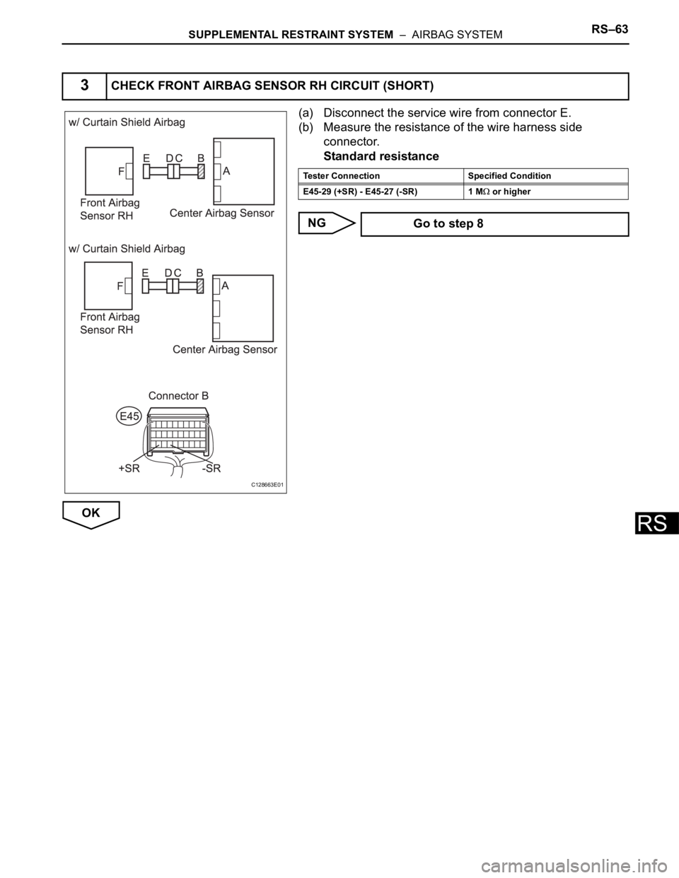
(a) Disconnect the service wire from connector E.
(b) Measure the resistance of the wire harness side
connector.
Standard resistance
NG
OK
3CHECK FRONT AIRBAG SENSOR RH CIRCUIT (SHORT)
C128663E01
Tester Connection Specified Condition
E45-29 (+SR) - E45-27 (-SR) 1 M
or higher
Go to step 8
Page 1713 of 2000

RS–64SUPPLEMENTAL RESTRAINT SYSTEM – AIRBAG SYSTEM
RS
(a) Connect the cable to the negative (-) battery terminal,
and wait for at least 2 seconds.
(b) Turn the ignition switch ON.
(c) Measure the voltage of the wire harness side connector.
Standard voltage
NG
OK
4CHECK FRONT AIRBAG SENSOR RH CIRCUIT (TO B+)
C128663E01
Tester Connection Specified Condition
E45-29 (+SR) -Body ground Below 1 V
E45-27 (-SR) - Body ground Below 1 V
Go to step 9