sensor TOYOTA RAV4 2006 Service Repair Manual
[x] Cancel search | Manufacturer: TOYOTA, Model Year: 2006, Model line: RAV4, Model: TOYOTA RAV4 2006Pages: 2000, PDF Size: 45.84 MB
Page 1678 of 2000
SUPPLEMENTAL RESTRAINT SYSTEM – AIRBAG SYSTEMRS–29
RS
HINT:
* : In case of a frontal collision, the ignition signal
could be output with the deceleration sensor ON
signal even without a signal from the front airbag
sensor.
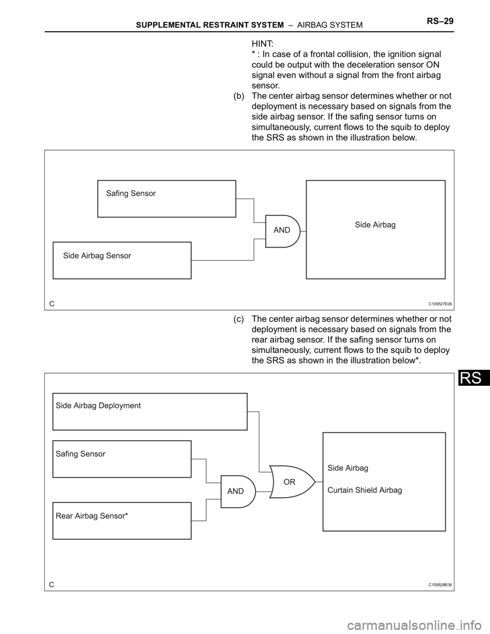
(b) The center airbag sensor determines whether or not
deployment is necessary based on signals from the
side airbag sensor. If the safing sensor turns on
simultaneously, current flows to the squib to deploy
the SRS as shown in the illustration below.
(c) The center airbag sensor determines whether or not
deployment is necessary based on signals from the
rear airbag sensor. If the safing sensor turns on
simultaneously, current flows to the squib to deploy
the SRS as shown in the illustration below*.
C109527E06
C109528E06
Page 1679 of 2000
RS–30SUPPLEMENTAL RESTRAINT SYSTEM – AIRBAG SYSTEM
RS
HINT:
*: If the side airbag deploys, the curtain shield
airbag will also deploy, regardless of whether the
signal is output from the rear airbag sensor.
(d) The center airbag sensor contains a roll rate sensor
and roll rate sensor (that determine the inclination
angle the vehicle) and a lateral deceleration sensor
(that determine the lateral force that is applied to the
vehicle). These sensors detect the vehicle's roll
angle (a), rotational speed (b), and lateral
acceleration speed (c). Based on the information
obtained from sensors, the airbag sensor makes an
overall judgment of the vehicle's roll angle (a),
rotational speed (b), and lateral acceleration speed
(c). If the airbag sensor determines that the vehicle
has rolled over due to cause other than the side
collision, it deploys the right and left curtain shield
airbag and the front right and left seat belt
pretensioner.
Page 1685 of 2000
RS–36SUPPLEMENTAL RESTRAINT SYSTEM – AIRBAG SYSTEM
RS
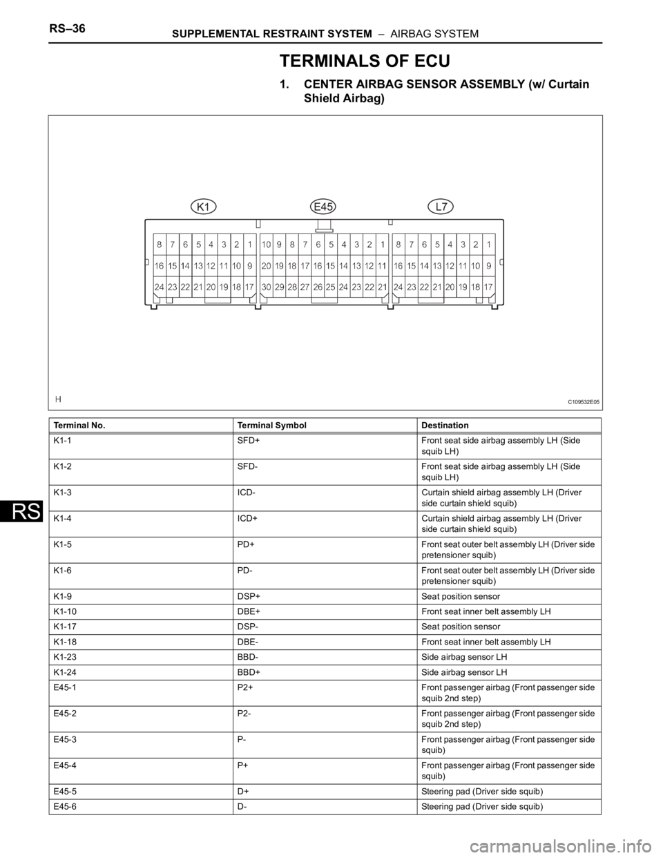
TERMINALS OF ECU
1. CENTER AIRBAG SENSOR ASSEMBLY (w/ Curtain
Shield Airbag)
Terminal No. Terminal Symbol Destination
K1-1 SFD+ Front seat side airbag assembly LH (Side
squib LH)
K1-2 SFD- Front seat side airbag assembly LH (Side
squib LH)
K1-3 ICD- Curtain shield airbag assembly LH (Driver
side curtain shield squib)
K1-4 ICD+ Curtain shield airbag assembly LH (Driver
side curtain shield squib)
K1-5 PD+ Front seat outer belt assembly LH (Driver side
pretensioner squib)
K1-6 PD- Front seat outer belt assembly LH (Driver side
pretensioner squib)
K1-9 DSP+ Seat position sensor
K1-10 DBE+ Front seat inner belt assembly LH
K1-17 DSP- Seat position sensor
K1-18 DBE- Front seat inner belt assembly LH
K1-23 BBD- Side airbag sensor LH
K1-24 BBD+ Side airbag sensor LH
E45-1 P2+ Front passenger airbag (Front passenger side
squib 2nd step)
E45-2 P2- Front passenger airbag (Front passenger side
squib 2nd step)
E45-3 P- Front passenger airbag (Front passenger side
squib)
E45-4 P+ Front passenger airbag (Front passenger side
squib)
E45-5 D+ Steering pad (Driver side squib)
E45-6 D- Steering pad (Driver side squib)
C109532E05
Page 1686 of 2000
SUPPLEMENTAL RESTRAINT SYSTEM – AIRBAG SYSTEMRS–37
RS
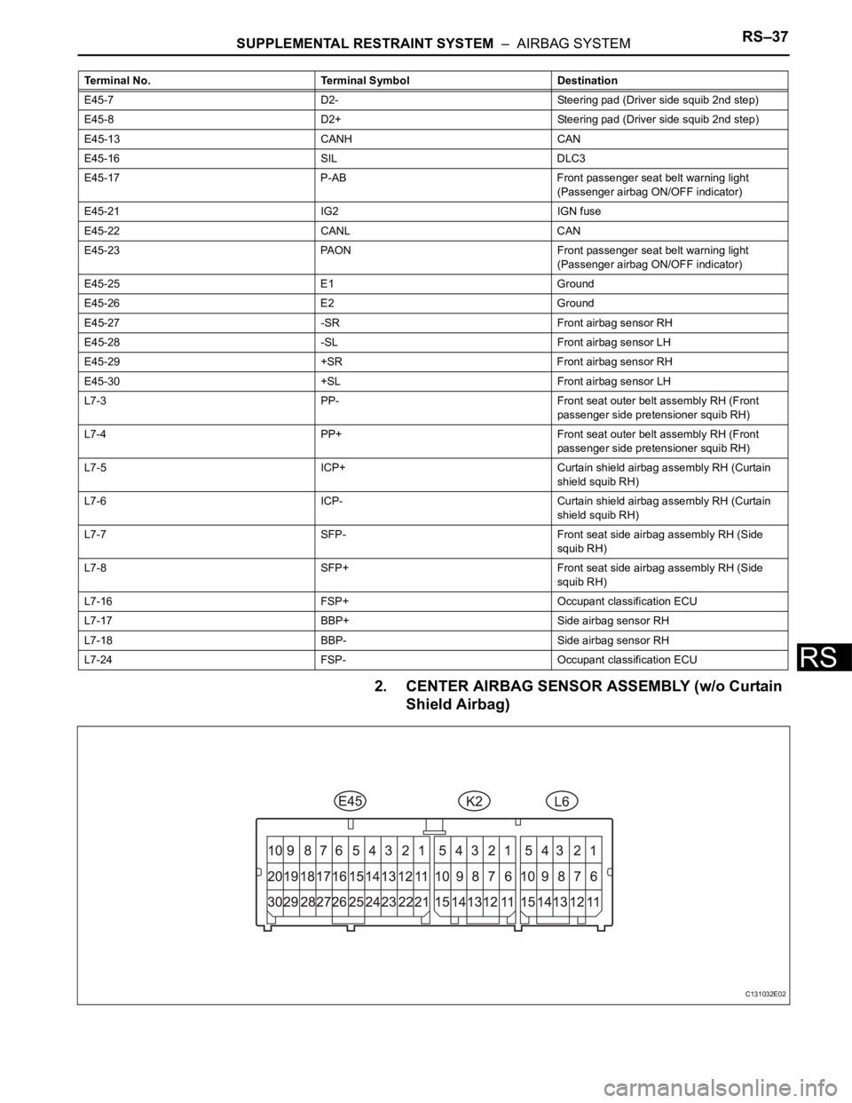
2. CENTER AIRBAG SENSOR ASSEMBLY (w/o Curtain
Shield Airbag)
E45-7 D2- Steering pad (Driver side squib 2nd step)
E45-8 D2+ Steering pad (Driver side squib 2nd step)
E45-13 CANH CAN
E45-16 SIL DLC3
E45-17 P-AB Front passenger seat belt warning light
(Passenger airbag ON/OFF indicator)
E45-21 IG2 IGN fuse
E45-22 CANL CAN
E45-23 PAON Front passenger seat belt warning light
(Passenger airbag ON/OFF indicator)
E45-25 E1 Ground
E45-26 E2 Ground
E45-27 -SR Front airbag sensor RH
E45-28 -SL Front airbag sensor LH
E45-29 +SR Front airbag sensor RH
E45-30 +SL Front airbag sensor LH
L7-3 PP- Front seat outer belt assembly RH (Front
passenger side pretensioner squib RH)
L7-4 PP+ Front seat outer belt assembly RH (Front
passenger side pretensioner squib RH)
L7-5 ICP+ Curtain shield airbag assembly RH (Curtain
shield squib RH)
L7-6 ICP- Curtain shield airbag assembly RH (Curtain
shield squib RH)
L7-7 SFP- Front seat side airbag assembly RH (Side
squib RH)
L7-8 SFP+ Front seat side airbag assembly RH (Side
squib RH)
L7-16 FSP+ Occupant classification ECU
L7-17 BBP+ Side airbag sensor RH
L7-18 BBP- Side airbag sensor RH
L7-24 FSP- Occupant classification ECU Terminal No. Terminal Symbol Destination
C131032E02
Page 1687 of 2000
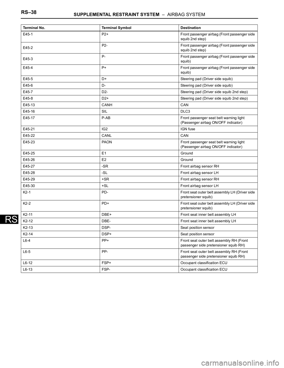
RS–38SUPPLEMENTAL RESTRAINT SYSTEM – AIRBAG SYSTEM
RS
Terminal No. Terminal Symbol Destination
E45-1 P2+ Front passenger airbag (Front passenger side
squib 2nd step)
E45-2P2- Front passenger airbag (Front passenger side
squib 2nd step)
E45-3P- Front passenger airbag (Front passenger side
squib)
E45-4 P+ Front passenger airbag (Front passenger side
squib)
E45-5 D+ Steering pad (Driver side squib)
E45-6 D- Steering pad (Driver side squib)
E45-7 D2- Steering pad (Driver side squib 2nd step)
E45-8 D2+ Steering pad (Driver side squib 2nd step)
E45-13 CANH CAN
E45-16 SIL DLC3
E45-17 P-AB Front passenger seat belt warning light
(Passenger airbag ON/OFF indicator)
E45-21 IG2 IGN fuse
E45-22 CANL CAN
E45-23 PAON Front passenger seat belt warning light
(Passenger airbag ON/OFF indicator)
E45-25 E1 Ground
E45-26 E2 Ground
E45-27 -SR Front airbag sensor RH
E45-28 -SL Front airbag sensor LH
E45-29 +SR Front airbag sensor RH
E45-30 +SL Front airbag sensor LH
K2-1 PD- Front seat outer belt assembly LH (Driver side
pretensioner squib)
K2-2 PD+ Front seat outer belt assembly LH (Driver side
pretensioner squib)
K2-11 DBE+ Front seat inner belt assembly LH
K2-12 DBE- Front seat inner belt assembly LH
K2-13 DSP- Seat position sensor
K2-14 DSP+ Seat position sensor
L6-4 PP+ Front seat outer belt assembly RH (Front
passenger side pretensioner squib RH)
L6-5 PP- Front seat outer belt assembly RH (Front
passenger side pretensioner squib RH)
L6-12 FSP+ Occupant classification ECU
L6-13 FSP- Occupant classification ECU
Page 1688 of 2000
SUPPLEMENTAL RESTRAINT SYSTEM – AIRBAG SYSTEMRS–39
RS
DIAGNOSIS SYSTEM
1. DESCRIPTION
The center airbag sensor controls the functions of the
Supplemental Restraint System (SRS) on the vehicle.
Data of the SRS can be read in the Data Link Connector
3 (DLC3) of the vehicle. When the system seems to be
malfunctioning, use the intelligent tester to check for a
malfunction and perform repairs.
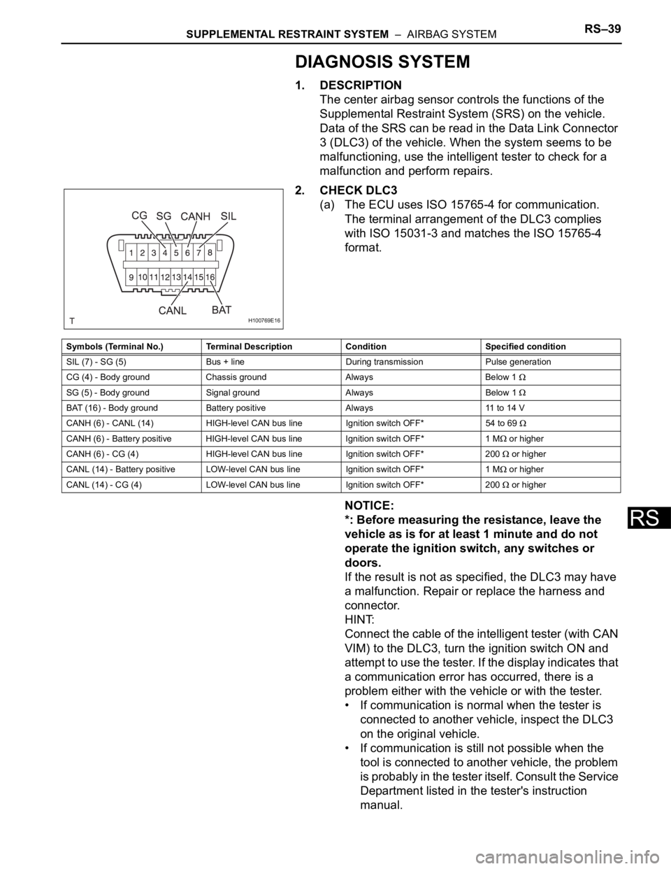
2. CHECK DLC3
(a) The ECU uses ISO 15765-4 for communication.
The terminal arrangement of the DLC3 complies
with ISO 15031-3 and matches the ISO 15765-4
format.
NOTICE:
*: Before measuring the resistance, leave the
vehicle as is for at least 1 minute and do not
operate the ignition switch, any switches or
doors.
If the result is not as specified, the DLC3 may have
a malfunction. Repair or replace the harness and
connector.
HINT:
Connect the cable of the intelligent tester (with CAN
VIM) to the DLC3, turn the ignition switch ON and
attempt to use the tester. If the display indicates that
a communication error has occurred, there is a
problem either with the vehicle or with the tester.
• If communication is normal when the tester is
connected to another vehicle, inspect the DLC3
on the original vehicle.
• If communication is still not possible when the
tool is connected to another vehicle, the problem
is probably in the tester itself. Consult the Service
Department listed in the tester's instruction
manual.
H100769E16
Symbols (Terminal No.) Terminal Description Condition Specified condition
SIL (7) - SG (5) Bus + line During transmission Pulse generation
CG (4) - Body ground Chassis ground Always Below 1
SG (5) - Body ground Signal ground Always Below 1
BAT (16) - Body ground Battery positive Always 11 to 14 V
CANH (6) - CANL (14) HIGH-level CAN bus line Ignition switch OFF*54 to 69
CANH (6) - Battery positive HIGH-level CAN bus line Ignition switch OFF* 1 M or higher
CANH (6) - CG (4) HIGH-level CAN bus line Ignition switch OFF* 200
or higher
CANL (14) - Battery positive LOW-level CAN bus line Ignition switch OFF* 1 M
or higher
CANL (14) - CG (4) LOW-level CAN bus line Ignition switch OFF* 200
or higher
Page 1689 of 2000
RS–40SUPPLEMENTAL RESTRAINT SYSTEM – AIRBAG SYSTEM
RS
3. SYMPTOM SIMULATION
HINT:
The most difficult case in troubleshooting is when no
problem symptoms occur. In such a case, a through
problem analysis must be carried out. A simulation of the
same or similar conditions and environment in which the
problem occurred in the customer's vehicle should be
carried out. No matter how much skill or experience a
technician has, troubleshooting without confirming the
problem symptoms will lead to important repairs being
overlooked and mistakes or delays.
This leads to a standstill in troubleshooting.
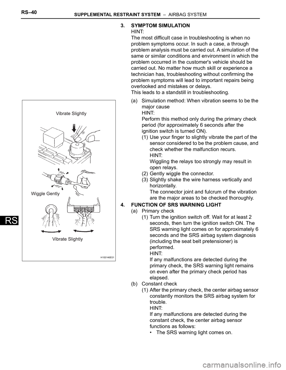
(a) Simulation method: When vibration seems to be the
major cause
HINT:
Perform this method only during the primary check
period (for approximately 6 seconds after the
ignition switch is turned ON).
(1) Use your finger to slightly vibrate the part of the
sensor considered to be the problem cause, and
check whether the malfunction recurs.
HINT:
Wiggling the relays too strongly may result in
open relays.
(2) Gently wiggle the connector.
(3) Slightly shake the wire harness vertically and
horizontally.
The connector joint and fulcrum of the vibration
are the major areas to be checked thoroughly.
4. FUNCTION OF SRS WARNING LIGHT
(a) Primary check
(1) Turn the ignition switch off. Wait for at least 2
seconds, then turn the ignition switch ON. The
SRS warning light comes on for approximately 6
seconds and the SRS airbag system diagnosis
(including the seat belt pretensioner) is
performed.
HINT:
If any malfunctions are detected during the
primary check, the SRS warning light remains
on even after the primary check period has
elapsed.
(b) Constant check
(1) After the primary check, the center airbag sensor
constantly monitors the SRS airbag system for
trouble.
HINT:
If any malfunctions are detected during the
constant check, the center airbag sensor
functions as follows:
• The SRS warning light comes on.
H100146E01
Page 1690 of 2000
SUPPLEMENTAL RESTRAINT SYSTEM – AIRBAG SYSTEMRS–41
RS
• The SRS warning light goes off, and then
comes on again. This blinking pattern
indicates a source voltage drop. The SRS
warning light goes off 10 seconds after the
source voltage returns to normal.
(c) Review
(1) When the airbag system is normal:
The SRS warning light comes on only during the
primary check period (for approximately 6
seconds after the ignition switch is turned ON).
(2) When the airbag system malfunctions:
• The SRS warning light blinks after the
primary check period has elapsed.
• The SRS warning light goes off after the
primary check, but comes on again during the
constant check.
• The SRS warning light remains off even after
the ignition switch is turned from LOCK to
ON. However, if malfunctions such as an
open circuit have occurred in the wire
harness between the meter and ECU, the
warning light comes on 10 seconds after the
ignition switch is turned ON.
HINT:
The center airbag sensor keeps the SRS
warning light on if any malfunctions have been
detected in the airbag system.
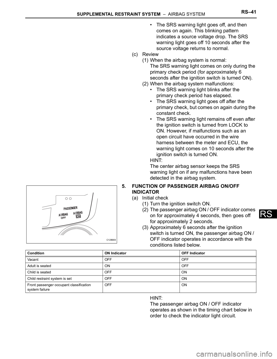
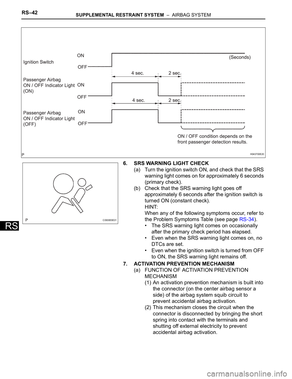
5. FUNCTION OF PASSENGER AIRBAG ON/OFF
INDICATOR
(a) Initial check
(1) Turn the ignition switch ON.
(2) The passenger airbag ON / OFF indicator comes
on for approximately 4 seconds, then goes off
for approximately 2 seconds.
(3) Approximately 6 seconds after the ignition
switch is turned ON, the passenger airbag ON /
OFF indicator operates in accordance with the
conditions listed below.
HINT:
The passenger airbag ON / OFF indicator
operates as shown in the timing chart below in
order to check the indicator light circuit.
C128669
Condition ON Indicator OFF Indicator
Va c a n t O F F O F F
Adult is seated ON OFF
Child is seated OFF ON
Child restraint system is set OFF ON
Front passenger occupant classification
system failureOFF ON
Page 1691 of 2000
RS–42SUPPLEMENTAL RESTRAINT SYSTEM – AIRBAG SYSTEM
RS
6. SRS WARNING LIGHT CHECK
(a) Turn the ignition switch ON, and check that the SRS
warning light comes on for approximately 6 seconds
(primary check).
(b) Check that the SRS warning light goes off
approximately 6 seconds after the ignition switch is
turned ON (constant check).
HINT:
When any of the following symptoms occur, refer to
the Problem Symptoms Table (see page RS-34).
• The SRS warning light comes on occasionally
after the primary check period has elapsed.
• Even when the SRS warning light comes on, no
DTCs are set.
• Even when the ignition switch is turned from OFF
to ON, the SRS warning light remains off.
7. ACTIVATION PREVENTION MECHANISM
(a) FUNCTION OF ACTIVATION PREVENTION
MECHANISM
(1) An activation prevention mechanism is built into
the connector (on the center airbag sensor a
side) of the airbag system squib circuit to
prevent accidental airbag activation.
(2) This mechanism closes the circuit when the
connector is disconnected by bringing the short
spring into contact with the terminals and
shutting off external electricity to prevent
accidental airbag activation.
H043700E20
C093955E01
Page 1700 of 2000
SUPPLEMENTAL RESTRAINT SYSTEM – AIRBAG SYSTEMRS–51
RS
(c) Read the DTCs.
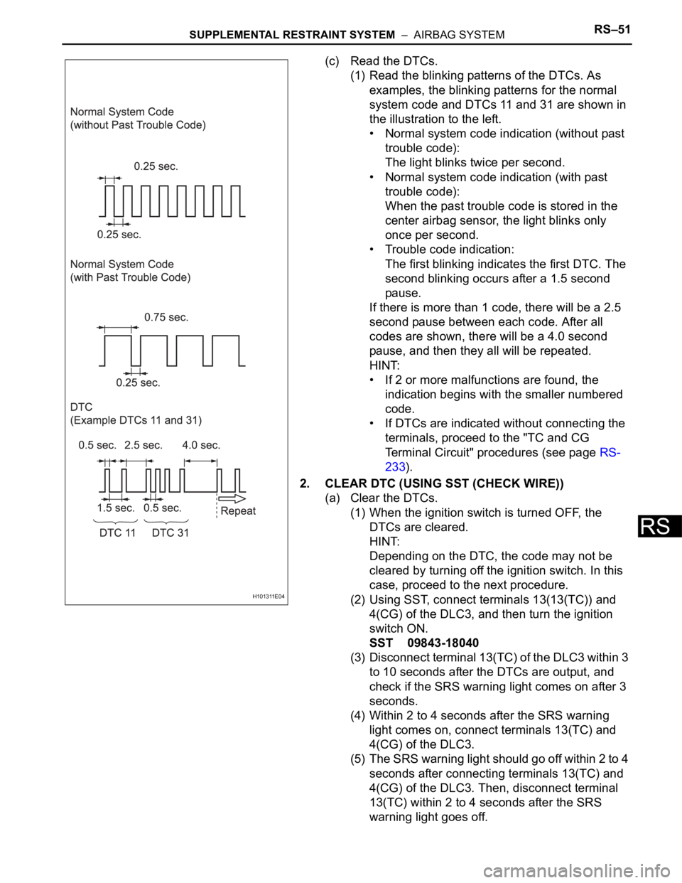
(1) Read the blinking patterns of the DTCs. As
examples, the blinking patterns for the normal
system code and DTCs 11 and 31 are shown in
the illustration to the left.
• Normal system code indication (without past
trouble code):
The light blinks twice per second.
• Normal system code indication (with past
trouble code):
When the past trouble code is stored in the
center airbag sensor, the light blinks only
once per second.
• Trouble code indication:
The first blinking indicates the first DTC. The
second blinking occurs after a 1.5 second
pause.
If there is more than 1 code, there will be a 2.5
second pause between each code. After all
codes are shown, there will be a 4.0 second
pause, and then they all will be repeated.
HINT:
• If 2 or more malfunctions are found, the
indication begins with the smaller numbered
code.
• If DTCs are indicated without connecting the
terminals, proceed to the "TC and CG
Terminal Circuit" procedures (see page RS-
233).
2. CLEAR DTC (USING SST (CHECK WIRE))
(a) Clear the DTCs.
(1) When the ignition switch is turned OFF, the
DTCs are cleared.
HINT:
Depending on the DTC, the code may not be
cleared by turning off the ignition switch. In this
case, proceed to the next procedure.
(2) Using SST, connect terminals 13(13(TC)) and
4(CG) of the DLC3, and then turn the ignition
switch ON.
SST 09843-18040
(3) Disconnect terminal 13(TC) of the DLC3 within 3
to 10 seconds after the DTCs are output, and
check if the SRS warning light comes on after 3
seconds.
(4) Within 2 to 4 seconds after the SRS warning
light comes on, connect terminals 13(TC) and
4(CG) of the DLC3.
(5) The SRS warning light should go off within 2 to 4
seconds after connecting terminals 13(TC) and
4(CG) of the DLC3. Then, disconnect terminal
13(TC) within 2 to 4 seconds after the SRS
warning light goes off.
H101311E04