sensor TOYOTA RAV4 2006 Service Repair Manual
[x] Cancel search | Manufacturer: TOYOTA, Model Year: 2006, Model line: RAV4, Model: TOYOTA RAV4 2006Pages: 2000, PDF Size: 45.84 MB
Page 1609 of 2000
POWER STEERING – ELECTRONIC POWER STEERING SYSTEMPS–9
PS
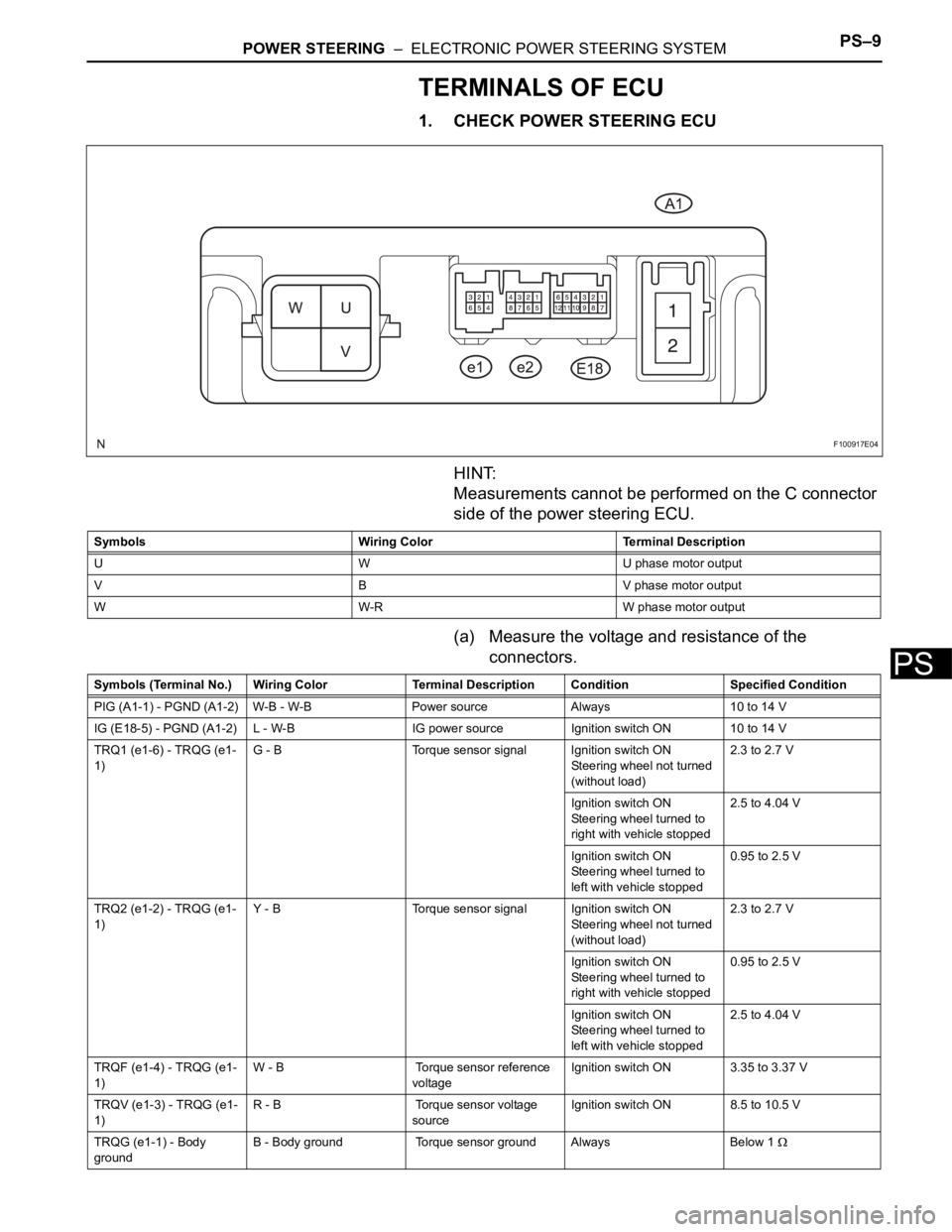
TERMINALS OF ECU
1. CHECK POWER STEERING ECU
HINT:
Measurements cannot be performed on the C connector
side of the power steering ECU.
(a) Measure the voltage and resistance of the
connectors.
F100917E04
Symbols Wiring Color Terminal Description
U W U phase motor output
V B V phase motor output
W W-R W phase motor output
Symbols (Terminal No.) Wiring Color Terminal Description ConditionSpecified Condition
PIG (A1-1) - PGND (A1-2) W-B - W-B Power source Always 10 to 14 V
IG (E18-5) - PGND (A1-2) L - W-B IG power source Ignition switch ON 10 to 14 V
TRQ1 (e1-6) - TRQG (e1-
1)G - B Torque sensor signal Ignition switch ON
Steering wheel not turned
(without load)2.3 to 2.7 V
Ignition switch ON
Steering wheel turned to
right with vehicle stopped2.5 to 4.04 V
Ignition switch ON
Steering wheel turned to
left with vehicle stopped0.95 to 2.5 V
TRQ2 (e1-2) - TRQG (e1-
1)Y - B Torque sensor signal Ignition switch ON
Steering wheel not turned
(without load)2.3 to 2.7 V
Ignition switch ON
Steering wheel turned to
right with vehicle stopped0.95 to 2.5 V
Ignition switch ON
Steering wheel turned to
left with vehicle stopped2.5 to 4.04 V
TRQF (e1-4) - TRQG (e1-
1)W - B Torque sensor reference
voltageIgnition switch ON 3.35 to 3.37 V
TRQV (e1-3) - TRQG (e1-
1)R - B Torque sensor voltage
sourceIgnition switch ON 8.5 to 10.5 V
TRQG (e1-1) - Body
groundB - Body ground Torque sensor ground Always Below 1
Page 1616 of 2000

PS–16POWER STEERING – ELECTRONIC POWER STEERING SYSTEM
PS
FAIL-SAFE CHART
If a problem occurs in the electric power steering system, the
P/S warning light will come on in the combination meter and
steering power assist will be stopped, fixed at a particular
point, or decreased simultaneously to protect the system.
Electronic power steering system
HINT:
The amount of power assist may be decreased to prevent the
motor and ECUs from overheating if the steering wheel is
continuously turned when the vehicle is either stopped or
driven at a low speed, or if the steering wheel is kept at either
full lock position for a long time. In such cases, the amount of
power assist returns to normal if the steering wheel is not
turned for approximately 10 minutes with the engine idling.
DTC No. Detection Condition Fail-safe
C1511/11 Torque sensor malfunction Power assist stops
C1512/11
C1513/11
C1514/11
C1521/25 Motor malfunction
C1524/24
C1528/12 Motor rotation angle sensor malfunction
C1531/25 ECU malfunction
C1532/25
C1534/25
C1551/25 IG power source voltage error
C1552/22 PIG power source voltage error
C1554/23 Power source relay malfunction
C1555/25 Motor relay malfunction
C1533/25 ECU malfunction Assist force restricted
U0073/49 CAN bus malfunction Amount of power assist is locked at 140 km/h
(87.5 mph) level of power assist
U0121/42 Skid control ECU communication error
U0105/41 ECM communication error Power assist stops
Page 1617 of 2000

POWER STEERING – ELECTRONIC POWER STEERING SYSTEMPS–17
PS
DATA LIST / ACTIVE TEST
1. READ DATA LIST
HINT:
Using the intelligent tester's DATA LIST allows switch,
sensor, actuator and other item values to be read without
removing any parts. Reading the DATA LIST early in
troubleshooting is one way to save time.
(a) Connect the intelligent tester (with CAN VIM) to the
DLC3.
(b) Turn the ignition switch ON and press the intelligent
tester main switch ON.
(c) Read the DATA LIST by following the directions on
the tester screen.
Tester Display Measurement Item/Range Normal Condition Reference Value
BATTERY VOLTAGE Battery voltage:
Min.: 0 V
Max.: 25.5 V- 10 to 14 V
SPD Vehicle speed from meter:
Min.: 0 km/h (0 mph)
Max.: 300 km/h (187.5 mph)Vehicle stopped 0 km/h (0 mph)
Vehicle driven at constant speed No significant fluctuation
SPD SIG INVALID Record of vehicle speed signal
invalid:
REC or UNREC- UNREC
ENGINE REV Show the engine revolution:
Min.: 0 rpm
Max.: 12800 rpmEngine is running at a constant
speedNo significant fluctuation
ENG REV INTER Record of engine revolution
signal interruption
REC or UNREC- UNREC
MOTOR ACTUAL Amount of current to motor:
Min.: -327.68 A
Max.: 327.67 APower steering is in operation Value changes in proportion to
steering effort
COMMAND VALUE Demanded amount of current to
motor:
Min.: -327.68 A
Max.: 327.68 APower steering is in operation Value changes in proportion to
steering effort
STR ANGL VEL Steering angle speed:
Min.: -32768
/sec.
Max.: 32767
/sec.Steering wheel is turned Value changes in proportion to
steering effort
STEERING TORQUE Steering wheel torque:
Min.: -7 Nm
Max.: 7 Nm--
THERMISTOR TEMP ECU substrate temperature:
Min.: -40
C
Max.: 150
CIgnition switch ON -
PIG SUPPLY Power source voltage to activate
motor:
Min.: 0 V
Max.: 20.1531 VPower steering in operation 10 to 14 V
IG SUPPLY ECU power source voltage:
Min.: 0 V
Max.: 20.1531 VIgnition switch ON 10 to 14 V
MTR OVERHEAT Continuous overheat prevention
control record:
REC or UNREC- UNREC
MTR LOW POWER PIG power source voltage drop
record:
REC or UNREC- UNREC
Page 1619 of 2000
POWER STEERING – ELECTRONIC POWER STEERING SYSTEMPS–19
PS
DIAGNOSTIC TROUBLE CODE CHART
HINT:
If any DTCs are displayed during the DTC check, inspect the
circuit listed for these DTCs. For details of each DTC, refer to
the page indicated in the DTC chart.
Electric Power Steering System
DTC No. Detection Item Trouble Area Normal Function
Return ConditionP/S Warning Light See page
C1511/11 Torque Sensor 1
Malfunction- Steering column
assembly (Torque
sensor)
- Power steering ECUIgnition switch ON
again
PS-18
C1512/11 Torque Sensor 2
Malfunction- Steering column
assembly (Torque
sensor)
- Power steering ECUIgnition switch ON
again
PS-18
C1513/11 Torque Sensor
Deviation Excessive- Steering column
assembly (Torque
sensor)
- Power steering ECUIgnition switch ON
again
PS-18
C1514/11 Torque Sensor Power
Supply Voltage
Malfunction- Steering column
assembly (Torque
sensor)
- Power steering ECUIgnition switch ON
again
PS-18
C1521/25 Short in Motor Circuit - Power steering ECU Ignition switch ON
again
PS-21
C1524/24 Motor Terminal
Voltage Malfunction- Steering column
assembly (Torque
sensor)
- Power steering ECUIgnition switch ON
again
PS-22
C1528/12 Motor Rotation Angle
Sensor Malfunction- Steering column
assembly (Torque
sensor)
- Power steering ECUIgnition switch ON
again
PS-24
C1531/25 ECU Malfunction - Power steering ECU Ignition switch ON
again
PS-26
C1532/25 ECU Malfunction - Power steering ECU Ignition switch ON
again
PS-26
C1533/25 Temperature Sensor
Circuit is Low or High- Power steering ECU Ignition switch ON
again or after normal
confirmation
PS-26
C1534/25 EEPROM
Malfunction- Power steering ECU Ignition switch ON
again
PS-26
C1551/25 IG Power Supply
Voltage Malfunction- ECU-IG1 fuse
- IG power source
circuit
- Power steering ECUIgnition switch ON
again or after normal
confirmation
PS-27
C1552/22 PIG Power Supply
Voltage Malfunction- PIG power source
circuit
- Power steering ECUIgnition switch ON
again or after normal
confirmation
PS-29
C1554/23 Power Supply Relay
Failure- PIG power source
circuit
- Power steering ECUIgnition switch ON
again
PS-31
C1555/25 Motor Relay Welding
Failure- Power steering ECU Ignition switch ON
again
PS-31
C1581/26 Assist Map Number
Un-Writing- Power steering ECU Assist map write or
ignition switch ON
again
PS-32
U0073/49 Control Module
Communication Bus
Off- CAN
communication
systemIgnition switch ON
again
PS-34
Page 1621 of 2000
POWER STEERING – ELECTRONIC POWER STEERING SYSTEMPS–21
PS
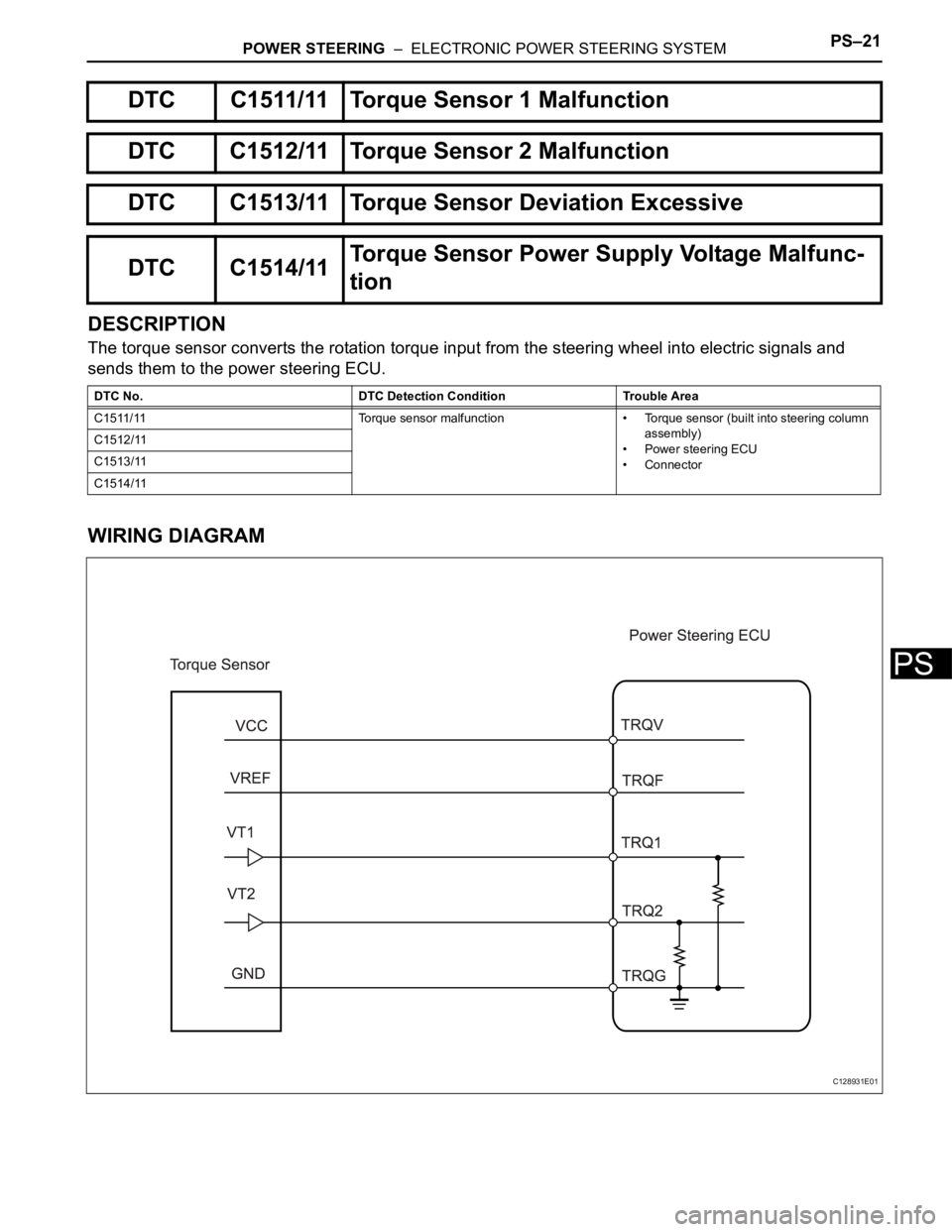
DESCRIPTION
The torque sensor converts the rotation torque input from the steering wheel into electric signals and
sends them to the power steering ECU.
WIRING DIAGRAM
DTC C1511/11 Torque Sensor 1 Malfunction
DTC C1512/11 Torque Sensor 2 Malfunction
DTC C1513/11 Torque Sensor Deviation Excessive
DTC C1514/11Torque Sensor Power Supply Voltage Malfunc-
tion
DTC No. DTC Detection Condition Trouble Area
C1511/11 Torque sensor malfunction • Torque sensor (built into steering column
assembly)
• Power steering ECU
• Connector C1512/11
C1513/11
C1514/11
C128931E01
Page 1622 of 2000
PS–22POWER STEERING – ELECTRONIC POWER STEERING SYSTEM
PS
INSPECTION PROCEDURE
(a) Check the installation condition of the torque sensor
connector.
OK:
Torque sensor connector is securely installed to
the power steering ECU.
Result
B
A
(a) Reinstall the torque sensor connector.
(b) Check for DTCs.
OK:
DTC is not output.
B
A
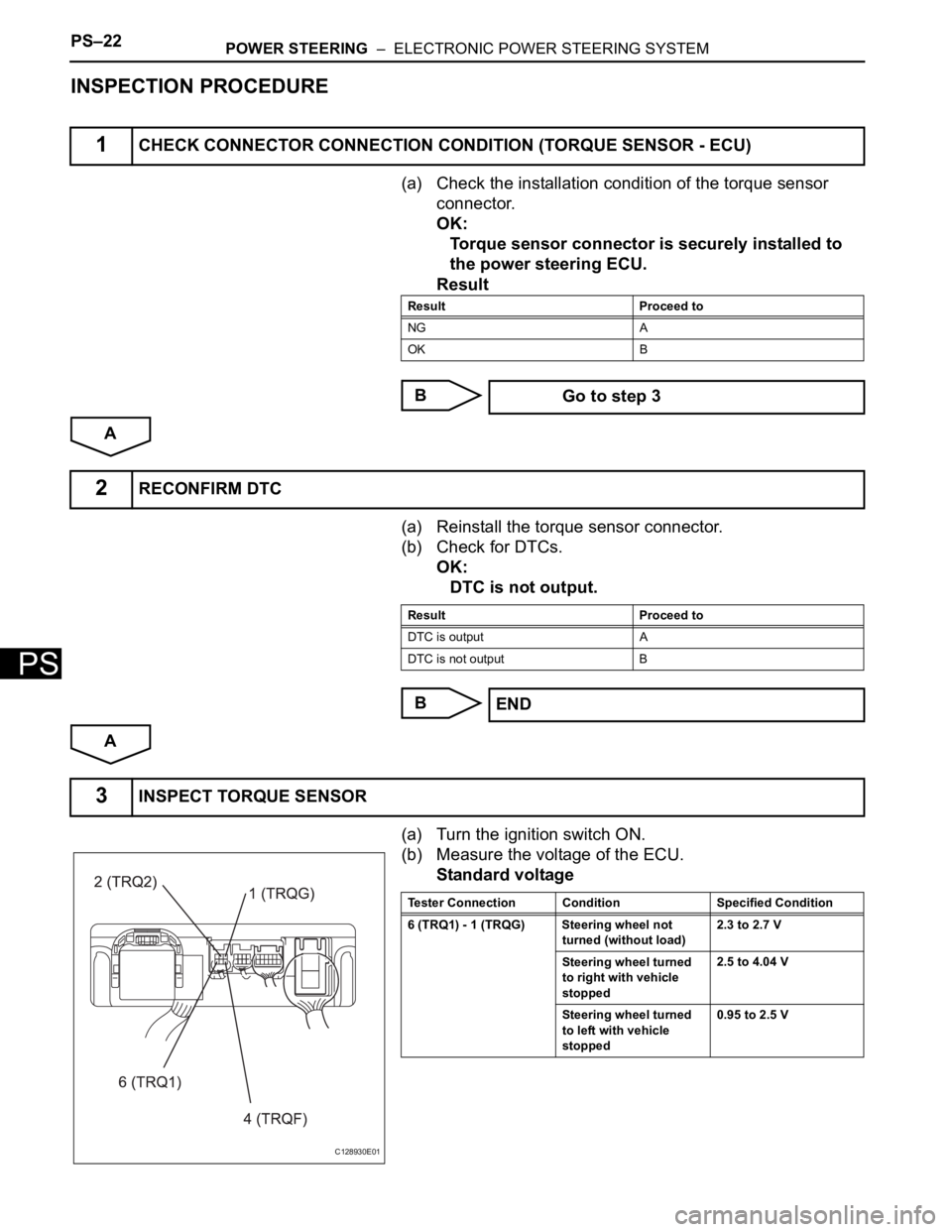
(a) Turn the ignition switch ON.
(b) Measure the voltage of the ECU.
Standard voltage
1CHECK CONNECTOR CONNECTION CONDITION (TORQUE SENSOR - ECU)
Result Proceed to
NG A
OK B
Go to step 3
2RECONFIRM DTC
Result Proceed to
DTC is output A
DTC is not output B
END
3INSPECT TORQUE SENSOR
C128930E01
Tester Connection Condition Specified Condition
6 (TRQ1) - 1 (TRQG) Steering wheel not
turned (without load)2.3 to 2.7 V
Steering wheel turned
to right with vehicle
stopped2.5 to 4.04 V
Steering wheel turned
to left with vehicle
stopped0.95 to 2.5 V
Page 1627 of 2000
POWER STEERING – ELECTRONIC POWER STEERING SYSTEMPS–27
PS
DESCRIPTION
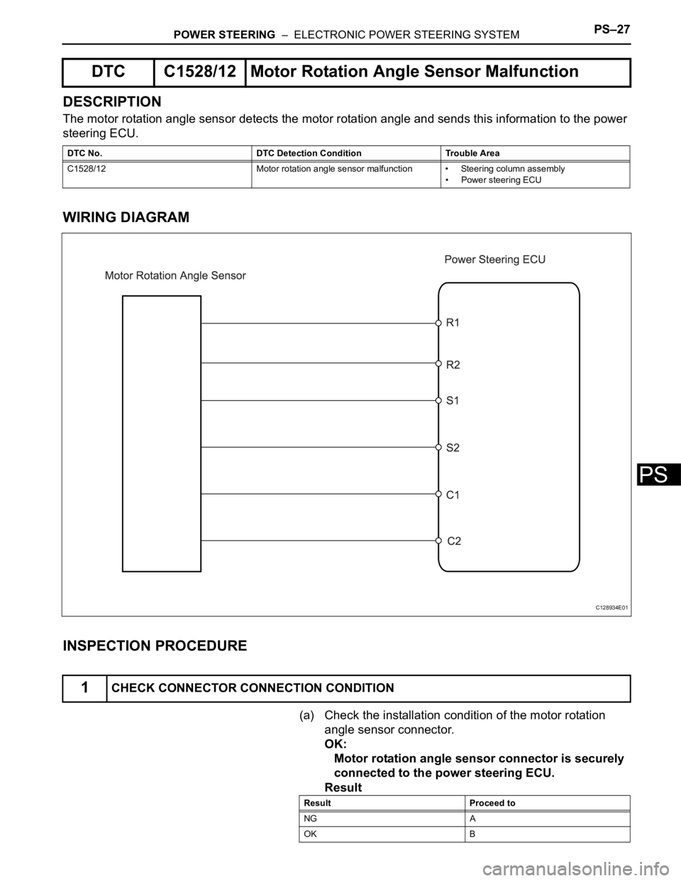
The motor rotation angle sensor detects the motor rotation angle and sends this information to the power
steering ECU.
WIRING DIAGRAM
INSPECTION PROCEDURE
(a) Check the installation condition of the motor rotation
angle sensor connector.
OK:
Motor rotation angle sensor connector is securely
connected to the power steering ECU.
Result
DTC C1528/12 Motor Rotation Angle Sensor Malfunction
DTC No. DTC Detection Condition Trouble Area
C1528/12 Motor rotation angle sensor malfunction • Steering column assembly
• Power steering ECU
1CHECK CONNECTOR CONNECTION CONDITION
C128934E01
Result Proceed to
NG A
OK B
Page 1628 of 2000
PS–28POWER STEERING – ELECTRONIC POWER STEERING SYSTEM
PS
B
A
(a) Reinstall motor rotation angle sensor connector.
(b) Check for DTC.
OK:
DTC is not output.
Result
B
A
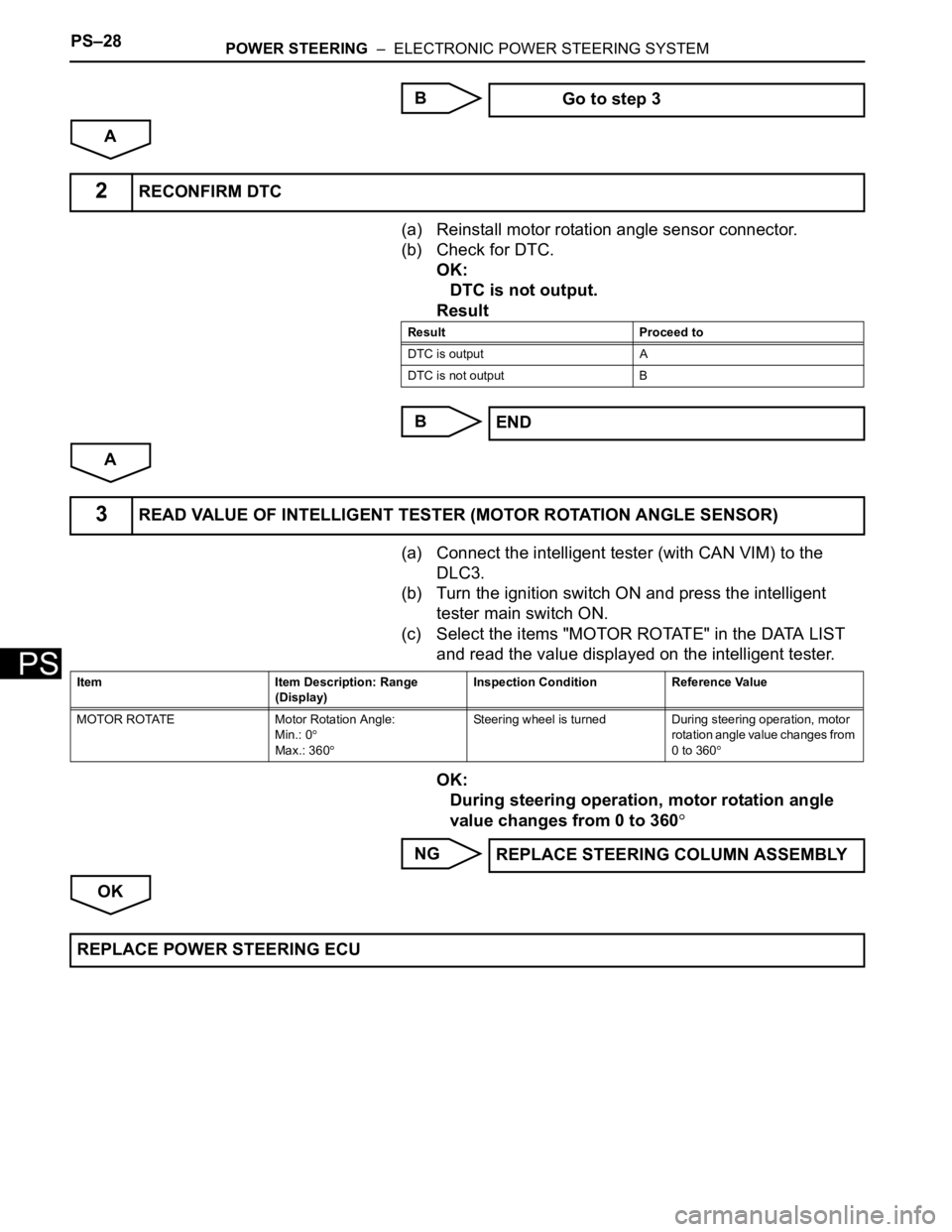
(a) Connect the intelligent tester (with CAN VIM) to the
DLC3.
(b) Turn the ignition switch ON and press the intelligent
tester main switch ON.
(c) Select the items "MOTOR ROTATE" in the DATA LIST
and read the value displayed on the intelligent tester.
OK:
During steering operation, motor rotation angle
value changes from 0 to 360
NG
OK Go to step 3
2RECONFIRM DTC
Result Proceed to
DTC is output A
DTC is not output B
END
3READ VALUE OF INTELLIGENT TESTER (MOTOR ROTATION ANGLE SENSOR)
Item Item Description: Range
(Display)Inspection Condition Reference Value
MOTOR ROTATE Motor Rotation Angle:
Min.: 0
Max.: 360
Steering wheel is turned During steering operation, motor
rotation angle value changes from
0 to 360
REPLACE STEERING COLUMN ASSEMBLY
REPLACE POWER STEERING ECU
Page 1629 of 2000
POWER STEERING – ELECTRONIC POWER STEERING SYSTEMPS–29
PS
DESCRIPTION
INSPECTION PROCEDURE
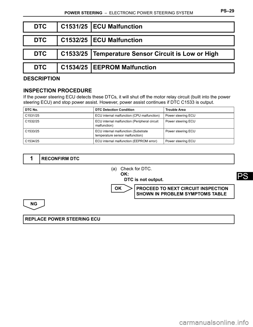
If the power steering ECU detects these DTCs, it will shut off the motor relay circuit (built into the power
steering ECU) and stop power assist. However, power assist continues if DTC C1533 is output.
(a) Check for DTC.
OK:
DTC is not output.
OK
NG
DTC C1531/25 ECU Malfunction
DTC C1532/25 ECU Malfunction
DTC C1533/25 Temperature Sensor Circuit is Low or High
DTC C1534/25 EEPROM Malfunction
DTC No. DTC Detection Condition Trouble Area
C1531/25 ECU internal malfunction (CPU malfunction) Power steering ECU
C1532/25 ECU internal malfunction (Peripheral circuit
malfunction)Power steering ECU
C1533/25 ECU internal malfunction (Substrate
temperature sensor malfunction)Power steering ECU
C1534/25 ECU internal malfunction (EEPROM error) Power steering ECU
1RECONFIRM DTC
PROCEED TO NEXT CIRCUIT INSPECTION
SHOWN IN PROBLEM SYMPTOMS TABLE
REPLACE POWER STEERING ECU
Page 1641 of 2000

AIR CONDITIONING – AIR CONDITIONING SYSTEM (for Automatic Air Conditioning Sys-
tem)AC–13
AC
SYSTEM DESCRIPTION
1. GENERAL
(a) The air conditioning system has the following
features:
• In accordance with the temperature set using the
temperature control switch, the air conditioning
amplifier determines the outlet temperature
based on the input signals from various sensors.
In addition, corrections are made in accordance
with the signals from the water temperature
sensor to control the outlet air temperature.
• Controls the blower motor in accordance with the
airflow volume determined by the air conditioning
amplifier based on the input signals from various
sensors.
• Automatically changes the outlets in accordance
with the outlet mode ratio that is determined by
the air conditioning amplifier based on the input
signals from various sensors.
• Based on the signals from the ambient
temperature sensor, this system calculates the
outside temperature and indicates it in the multi-
information display in the combination meter
assembly.
• The left/right independent temperature control
and neural network control make air conditioner
control available to suit the persons in the driver
seat and in the passenger seat.
• Turns the rear defogger and outside rear mirror
heaters on for 15 minutes when the rear
defogger switch is pressed. Turns them off if the
switch is pressed while they are operating.
• Checks the sensors in accordance with the
operation of the air conditioner switches.
• The air conditioning amplifier has the function of
controlling the indicator lighting.