sensor TOYOTA RAV4 2006 Service Repair Manual
[x] Cancel search | Manufacturer: TOYOTA, Model Year: 2006, Model line: RAV4, Model: TOYOTA RAV4 2006Pages: 2000, PDF Size: 45.84 MB
Page 1746 of 2000

SB–8SEAT BELT – SEAT BELT WARNING SYSTEM
SB
PROBLEM SYMPTOMS TABLE
HINT:
Use the table below to help determine the cause of the
problem symptom. The potential causes of the symptoms are
listed in order of probability in the "Suspected Area" column
of the table. Check each symptom by checking the suspected
areas in the order they are listed. Replace parts as
necessary.
Seat belt warning system
Symptom Suspected area See page
Diver side seat belt warning light does not operate1. Front seat inner belt LHSB-12
2. Center airbag sensor assemblySB-12
3. Combination meterSB-12
4. Wire harnessSB-12
Front passenger side seat belt warning light does not
operate1. Front seat inner belt RHSB-15
2. Combination meterSB-15
3. Occupant detection sensorSB-15
4. Heater control panelSB-15
5. Wire harnessSB-15
Page 1750 of 2000

SB–12SEAT BELT – SEAT BELT WARNING SYSTEM
SB
DATA LIST / ACTIVE TEST
1. ACTIVE TEST
HINT:
Performing the intelligent tester ACTIVE TEST allows
relay, VSV, actuator and other items to be operated
without removing any parts. Performing the ACTIVE
TEST early in troubleshooting is one way to save time.
The DATA LIST can be displayed during the ACTIVE
TEST.
(a) Connect the intelligent tester to the DLC3.
(b) Turn the ignition switch ON.
(c) Perform the ACTIVE TEST according to the display
on the tester.
Center airbag sensor:
Item Test Details Diagnostic Note
D-BELT REMIND D-SEAT BELT warning light (OFF / ON) Confirm that the vehicle is stopped, engine
idling
P-BELT REMIND P-SEAT BELT warning light (OFF / ON) Confirm that the vehicle is stopped, engine
idling
Page 1752 of 2000

SB–14SEAT BELT – SEAT BELT WARNING SYSTEM
SB
DESCRIPTION
When the ignition switch is ON, the center airbag sensor transmits front seat inner belt status signals to
the combination meter through the CAN bus line. If the driver seat belt is not fastened, the combination
meter blinks the driver side seat belt warning light. If the seat belt is fastened, the warning light goes off.
NOTICE:
The seat belt warning system uses the CAN bus line. Before troubleshooting the seat belt warning
system, perform "COMMUNICATION FUNCTION CHECK" by following "HOW TO PROCEED WITH
TROUBLESHOOTING" to confirm that the communication systems are normal.
Driver Side Seat Belt Warning Light does not Operate
Page 1754 of 2000

SB–16SEAT BELT – SEAT BELT WARNING SYSTEM
SB
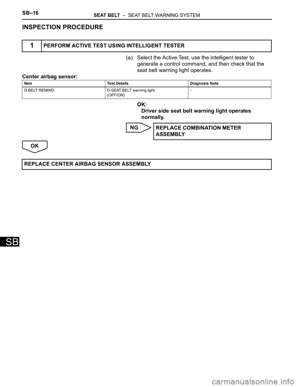
INSPECTION PROCEDURE
(a) Select the Active Test, use the intelligent tester to
generate a control command, and then check that the
seat belt warning light operates.
Center airbag sensor:
OK:
Driver side seat belt warning light operates
normally.
NG
OK
1PERFORM ACTIVE TEST USING INTELLIGENT TESTER
Item Test Details Diagnosis Note
D-BELT REMIND D-SEAT BELT warning light
(OFF/ON)-
REPLACE COMBINATION METER
ASSEMBLY
REPLACE CENTER AIRBAG SENSOR ASSEMBLY
Page 1755 of 2000

SEAT BELT – SEAT BELT WARNING SYSTEMSB–17
SB
DESCRIPTION
When the ignition switch is ON, the center airbag sensor transmits front seat inner belt status signals to
the combination meter through the CAN bus line. If the front passenger seat belt is not fastened, the
heater control panel (automatic A/C) or clock (manual A/C) blinks the front passenger seat belt warning
light. If the seat belt is fastened, the warning light goes off.
NOTICE:
The seat belt warning system uses the CAN bus line. Before troubleshooting the seat belt warning
system, perform "COMMUNICATION FUNCTION CHECK" by following "HOW TO PROCEED WITH
TROUBLESHOOTING" to confirm that the communication systems are normal.
Front Passenger Side Seat Belt Warning Light Malfunction
Page 1757 of 2000

SEAT BELT – SEAT BELT WARNING SYSTEMSB–19
SB
INSPECTION PROCEDURE
(a) Select the Active Test, use the intelligent tester to
generate a control command, and then check that the
seat belt warning light operates.
Center airbag sensor:
OK:
Passenger side seat belt warning light operates
normally.
OK
NG
(a) Check system.
B
A
(a) Disconnect the E23 panel connector.
(b) Measure the voltage and resistance of the wire harness
side connector.
Standard voltage
Standard resistance
NG
1PERFORM ACTIVE TEST BY INTELLIGENT TESTER
Item Test Details Diagnostic Note
P-BELT REMIND P-SEAT BELT warning light
(OFF/ON)Confirm that the vehicle is stopped, engine
idling
REPLACE CENTER AIRBAG SENSOR
ASSEMBLY
2CHECK A/C TYPE
A/C type Proceed to
for Automatic air conditioning system A
for Manual air conditioning system B
Go to step 6
3CHECK HEATER CONTROL PANEL (POWER SOURCE CIRCUIT)
B130079E01
Tester Connection Condition Specified Condition
E23-1 (+B) - Body
groundAlways 10 to 14 V
E23-2 (IG+) - Body
groundIgnition switch ON 10 to 14 V
E23-3 (ACC) - Body
groundIgnition switch ON
(ACC)10 to 14 V
Tester Connection Specified Condition
E23-7 (GND) - Body ground Below 1
REPAIR OR REPLACE HARNESS AND
CONNECTOR
Page 1792 of 2000

ENGINE IMMOBILISER – ENGINE IMMOBILISER SYSTEMEI–21
EI
DATA LIST / ACTIVE TEST
1. READ DATA LIST
HINT:
Using the intelligent tester's DATA LIST allows switch,
sensor, actuator and other item values to be read without
removing any parts. Reading the DATA LIST early in
troubleshooting is one way to save time.
(a) Connect the intelligent tester (with CAN VIM) to the
DLC3.
(b) Turn the ignition switch ON and turn the tester ON.
(c) Select the following menu items: DIAGNOSIS /
OBD/MOBD / IMMOBILISER / DATA LIST.
(d) Check the results by referring to the table below.
Transponder key ECU:
ItemMeasurement Item / Display
(Range)Normal Condition Diagnostic Note
KEY SWUnlock warning switch signal /
ON or OFFON: Key is in ignition key cylinder
OFF: No key is in ignition key
cylinder-
IG SW Ignition switch signal / ON or OFFON: Ignition switch ON (IG or
ACC)
OFF: Ignition switch OFF-
IMMOBILISERImmobiliser system status / SET
or UNSETSET: No key is in ignition key
cylinder
UNSET: Key is in ignition key
cylinder-
PERMIT (START)Engine starting control / OK or
NGOK: Engine start is permitted
NG: Engine start is not permitted-
RESPONSETransponder chip data / NG or
OKNG: Data error
OK: Data OK-
FRAME ERRORTransponder chip data / NG or
OKNG: Data error
OK: Data OK-
SERIAL NUMBERTransponder chip data / NG or
OKNG: Data error
OK: Data OK-
ENCRYPT CODETransponder chip data / NG or
OKNG: Data error
OK: Data OK-
STATUSTransponder chip data / NG or
OKNG: Data error
OK: Data OK-
BCCTransponder chip signal / NG or
OKNG: Incorrect data sent
OK: Correct data sent-
SUB KEYSub-key code signal / MATCH or
NOMATCHMATCH: Registered sub-key
code is sent
NOMATCH: Unmatched sub-key
code is sent-
MASTER KEYMaster key code signal / MATCH
or NOMATCHMATCH: Registered master key
code is sent
NOMATCH: Unmatched master
key code is sent-
REGIST SUB CODENumber of registered sub-keys /
min.: 0, max.: 15Number of registered sub-keys -
REGIST MAS CODENumber of registered master
keys / min.: 0, max.: 15Number of registered master
keys-
REG CODE SPACEKey registration code memory
space full / NOTFULL or FULLNOTFULL: Possible to register
more key codes
FULL: Cannot register any more
key codes-
Page 1813 of 2000

CC–14CRUISE CONTROL – CRUISE CONTROL SYSTEM
CC
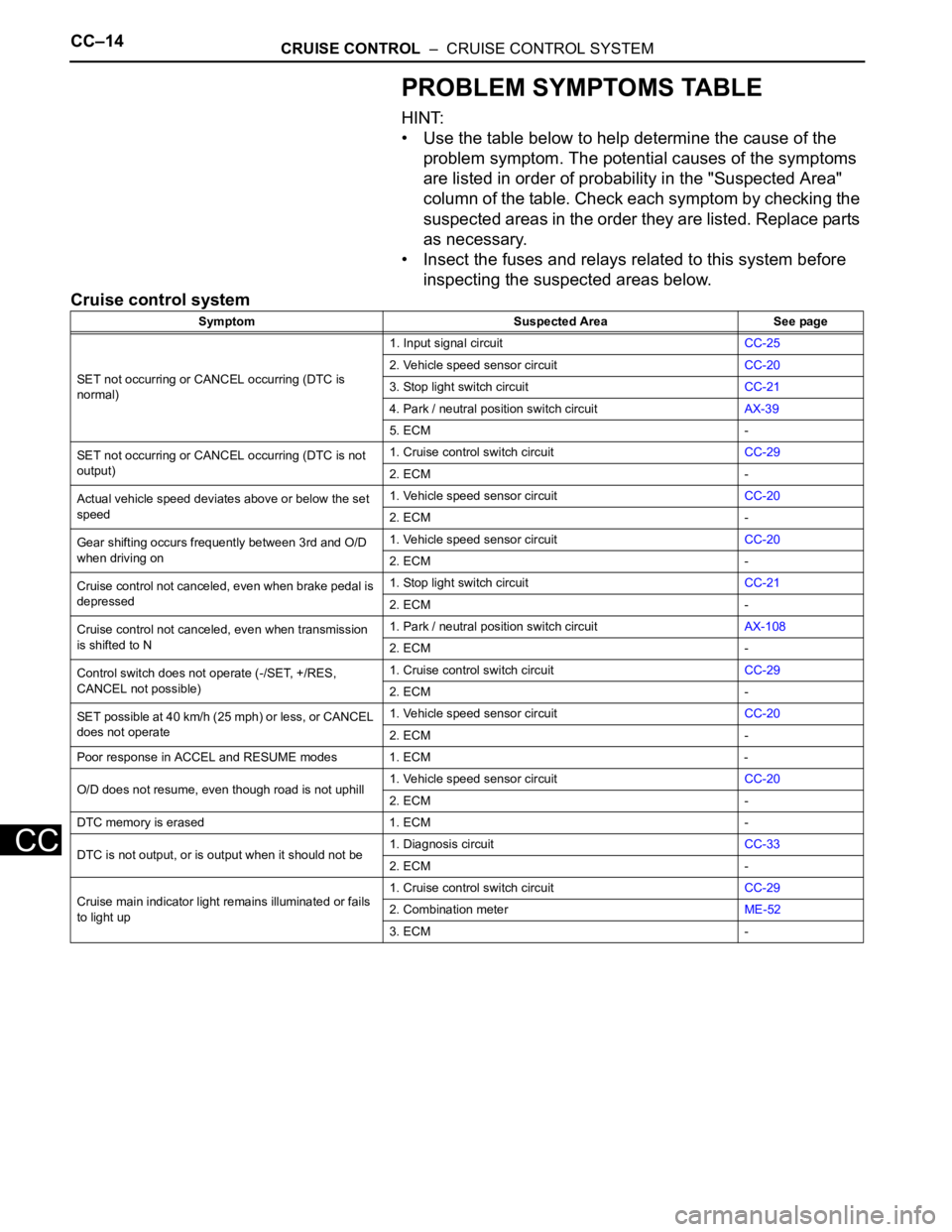
PROBLEM SYMPTOMS TABLE
HINT:
• Use the table below to help determine the cause of the
problem symptom. The potential causes of the symptoms
are listed in order of probability in the "Suspected Area"
column of the table. Check each symptom by checking the
suspected areas in the order they are listed. Replace parts
as necessary.
• Insect the fuses and relays related to this system before
inspecting the suspected areas below.
Cruise control system
Symptom Suspected Area See page
SET not occurring or CANCEL occurring (DTC is
normal)1. Input signal circuitCC-25
2. Vehicle speed sensor circuitCC-20
3. Stop light switch circuitCC-21
4. Park / neutral position switch circuitAX-39
5. ECM -
SET not occurring or CANCEL occurring (DTC is not
output)1. Cruise control switch circuitCC-29
2. ECM -
Actual vehicle speed deviates above or below the set
speed1. Vehicle speed sensor circuitCC-20
2. ECM -
Gear shifting occurs frequently between 3rd and O/D
when driving on1. Vehicle speed sensor circuitCC-20
2. ECM -
Cruise control not canceled, even when brake pedal is
depressed1. Stop light switch circuitCC-21
2. ECM -
Cruise control not canceled, even when transmission
is shifted to N1. Park / neutral position switch circuitAX-108
2. ECM -
Control switch does not operate (-/SET, +/RES,
CANCEL not possible)1. Cruise control switch circuitCC-29
2. ECM -
SET possible at 40 km/h (25 mph) or less, or CANCEL
does not operate1. Vehicle speed sensor circuitCC-20
2. ECM -
Poor response in ACCEL and RESUME modes 1. ECM -
O/D does not resume, even though road is not uphill1. Vehicle speed sensor circuitCC-20
2. ECM -
DTC memory is erased 1. ECM -
DTC is not output, or is output when it should not be1. Diagnosis circuitCC-33
2. ECM -
Cruise main indicator light remains illuminated or fails
to light up1. Cruise control switch circuitCC-29
2. Combination meterME-52
3. ECM -
Page 1816 of 2000

CRUISE CONTROL – CRUISE CONTROL SYSTEMCC–17
CC
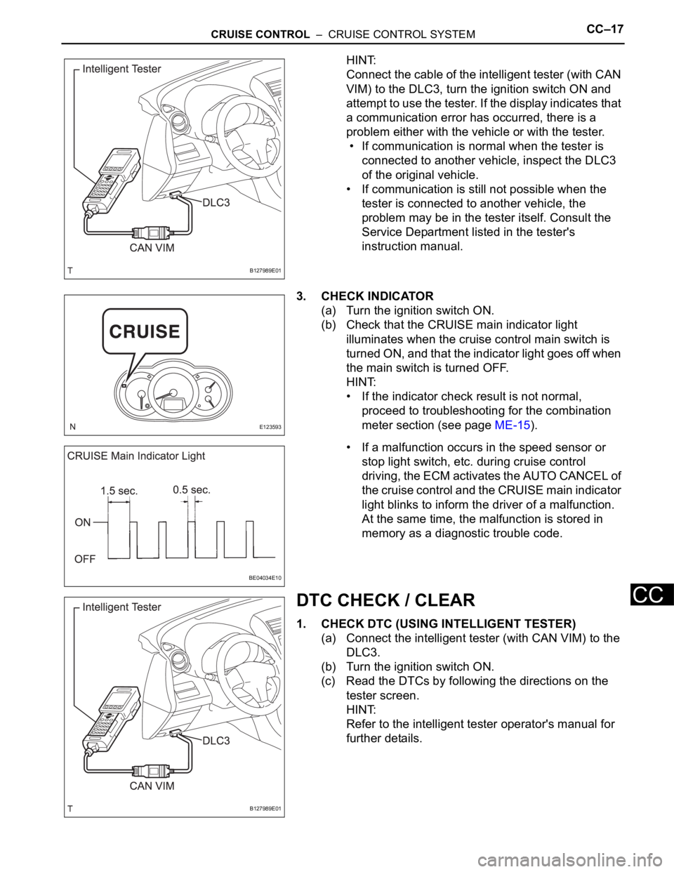
HINT:
Connect the cable of the intelligent tester (with CAN
VIM) to the DLC3, turn the ignition switch ON and
attempt to use the tester. If the display indicates that
a communication error has occurred, there is a
problem either with the vehicle or with the tester.
• If communication is normal when the tester is
connected to another vehicle, inspect the DLC3
of the original vehicle.
• If communication is still not possible when the
tester is connected to another vehicle, the
problem may be in the tester itself. Consult the
Service Department listed in the tester's
instruction manual.
3. CHECK INDICATOR
(a) Turn the ignition switch ON.
(b) Check that the CRUISE main indicator light
illuminates when the cruise control main switch is
turned ON, and that the indicator light goes off when
the main switch is turned OFF.
HINT:
• If the indicator check result is not normal,
proceed to troubleshooting for the combination
meter section (see page ME-15).
• If a malfunction occurs in the speed sensor or
stop light switch, etc. during cruise control
driving, the ECM activates the AUTO CANCEL of
the cruise control and the CRUISE main indicator
light blinks to inform the driver of a malfunction.
At the same time, the malfunction is stored in
memory as a diagnostic trouble code.
DTC CHECK / CLEAR
1. CHECK DTC (USING INTELLIGENT TESTER)
(a) Connect the intelligent tester (with CAN VIM) to the
DLC3.
(b) Turn the ignition switch ON.
(c) Read the DTCs by following the directions on the
tester screen.
HINT:
Refer to the intelligent tester operator's manual for
further details.
B127989E01
E123593
BE04034E10
B127989E01
Page 1819 of 2000

CC–20CRUISE CONTROL – CRUISE CONTROL SYSTEM
CC
FAIL-SAFE CHART
HINT:
If the following conditions are detected while the cruise
control is in operation, the system clears the stored vehicle
speed in the ECM and cancels the cruise control operation.
Cruise control system
HINT:
*: w/ VSC
Vehicle Condition Auto Cancel Condition Fail-safe Deactivation Condition
CRUISE main indicator light blinks• There is open or short in stop light switch
circuit
• There is problem with vehicle speed
signal
• There is problem with throttle position
sensor and motor
• VSC is damaged*
• There is communication malfunction
between VSC and ECM*Turn cruise control main switch ON again
CRUISE main indicator light blinks• There is problem with input circuit of stop
light switch circuit
• There is problem with cancel circuitTurn ignition switch ON