wheel TOYOTA RAV4 2006 Service Owner's Guide
[x] Cancel search | Manufacturer: TOYOTA, Model Year: 2006, Model line: RAV4, Model: TOYOTA RAV4 2006Pages: 2000, PDF Size: 45.84 MB
Page 648 of 2000
2AZ-FE ENGINE MECHANICAL – ENGINE ASSEMBLYEM–113
EM
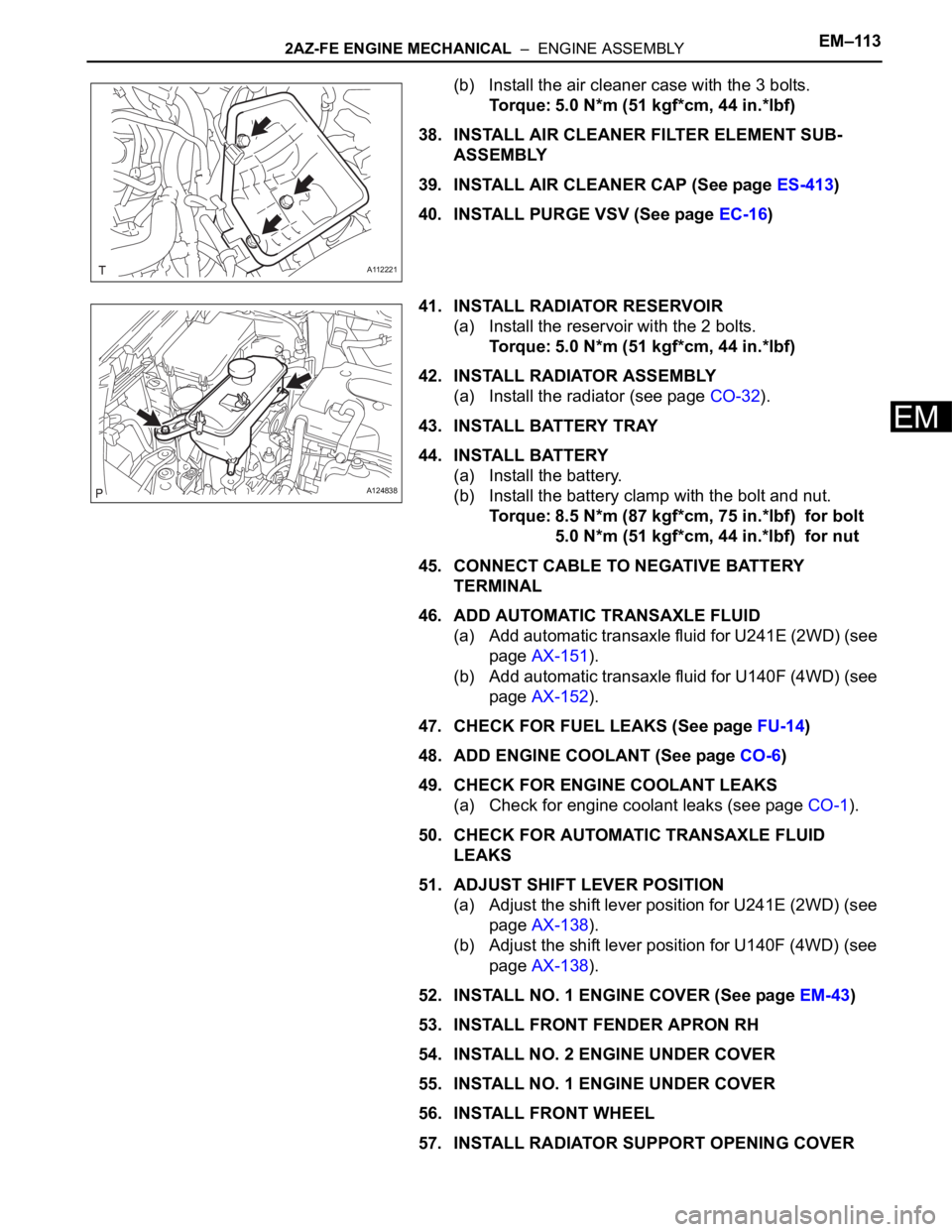
(b) Install the air cleaner case with the 3 bolts.
Torque: 5.0 N*m (51 kgf*cm, 44 in.*lbf)
38. INSTALL AIR CLEANER FILTER ELEMENT SUB-
ASSEMBLY
39. INSTALL AIR CLEANER CAP (See page ES-413)
40. INSTALL PURGE VSV (See page EC-16)
41. INSTALL RADIATOR RESERVOIR
(a) Install the reservoir with the 2 bolts.
Torque: 5.0 N*m (51 kgf*cm, 44 in.*lbf)
42. INSTALL RADIATOR ASSEMBLY
(a) Install the radiator (see page CO-32).
43. INSTALL BATTERY TRAY
44. INSTALL BATTERY
(a) Install the battery.
(b) Install the battery clamp with the bolt and nut.
Torque: 8.5 N*m (87 kgf*cm, 75 in.*lbf) for bolt
5.0 N*m (51 kgf*cm, 44 in.*lbf) for nut
45. CONNECT CABLE TO NEGATIVE BATTERY
TERMINAL
46. ADD AUTOMATIC TRANSAXLE FLUID
(a) Add automatic transaxle fluid for U241E (2WD) (see
page AX-151).
(b) Add automatic transaxle fluid for U140F (4WD) (see
page AX-152).
47. CHECK FOR FUEL LEAKS (See page FU-14)
48. ADD ENGINE COOLANT (See page CO-6)
49. CHECK FOR ENGINE COOLANT LEAKS
(a) Check for engine coolant leaks (see page CO-1).
50. CHECK FOR AUTOMATIC TRANSAXLE FLUID
LEAKS
51. ADJUST SHIFT LEVER POSITION
(a) Adjust the shift lever position for U241E (2WD) (see
page AX-138).
(b) Adjust the shift lever position for U140F (4WD) (see
page AX-138).
52. INSTALL NO. 1 ENGINE COVER (See page EM-43)
53. INSTALL FRONT FENDER APRON RH
54. INSTALL NO. 2 ENGINE UNDER COVER
55. INSTALL NO. 1 ENGINE UNDER COVER
56. INSTALL FRONT WHEEL
57. INSTALL RADIATOR SUPPORT OPENING COVER
A112221
A124838
Page 649 of 2000
EM–1142AZ-FE ENGINE MECHANICAL – ENGINE ASSEMBLY
EM
58. INSTALL HOOD SUB-ASSEMBLY
(a) Install the hood (see page ED-7).
(b) Adjust the hood (see page ED-5).
59. INSPECT AND ADJUST FRONT WHEEL ALIGNMENT
(a) Inspect and adjust the front wheel alignment (see
page SP-3).
60. PERFORM REGISTRATION
(a) When replacing the engine assembly, perform
vehicle stability control system recognition in ECM
(see page CC-12).
61. RESET MEMORY (for Automatic Transaxle)
(a) When replacing the engine assembly, perform the
RESET MEMORY procedure (A/T initialization) for
U241E (2WD) (see page AX-18) and for U140F
(4WD) (see page AX-18).
Page 681 of 2000
2GR-FE ENGINE MECHANICAL – ENGINE ASSEMBLYEM–35
EM
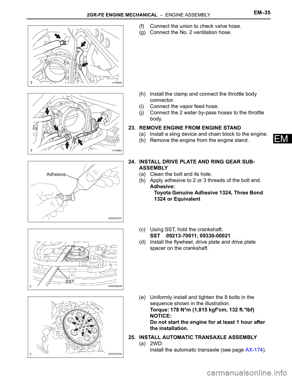
(f) Connect the union to check valve hose.
(g) Connect the No. 2 ventilation hose.
(h) Install the clamp and connect the throttle body
connector.
(i) Connect the vapor feed hose.
(j) Connect the 2 water by-pass hoses to the throttle
body.
23. REMOVE ENGINE FROM ENGINE STAND
(a) Install a sling device and chain block to the engine.
(b) Remove the engine from the engine stand.
24. INSTALL DRIVE PLATE AND RING GEAR SUB-
ASSEMBLY
(a) Clean the bolt and its hole.
(b) Apply adhesive to 2 or 3 threads of the bolt end.
Adhesive:
Toyota Genuine Adhesive 1324, Three Bond
1324 or Equivalent
(c) Using SST, hold the crankshaft.
SST 09213-70011, 09330-00021
(d) Install the flywheel, drive plate and drive plate
spacer on the crankshaft.
(e) Uniformly install and tighten the 8 bolts in the
sequence shown in the illustration.
Torque: 178 N*m (1,815 kgf*cm, 132 ft.*lbf)
NOTICE:
Do not start the engine for at least 1 hour after
the installation.
25. INSTALL AUTOMATIC TRANSAXLE ASSEMBLY
(a) 2WD:
Install the automatic transaxle (see page AX-174).
A139490
A129464
A054047E01
A076326E04
A076327E03
Page 684 of 2000
EM–382GR-FE ENGINE MECHANICAL – ENGINE ASSEMBLY
EM
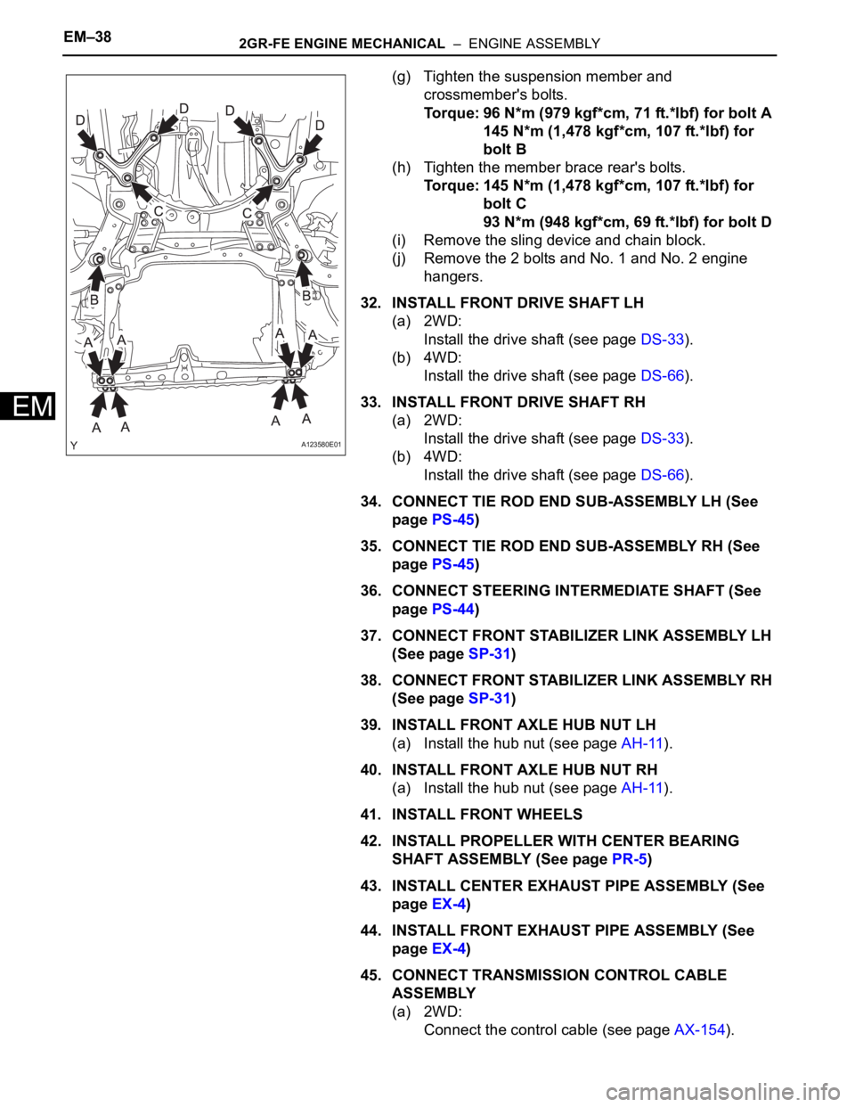
(g) Tighten the suspension member and
crossmember's bolts.
Torque: 96 N*m (979 kgf*cm, 71 ft.*lbf) for bolt A
145 N*m (1,478 kgf*cm, 107 ft.*lbf) for
bolt B
(h) Tighten the member brace rear's bolts.
Torque: 145 N*m (1,478 kgf*cm, 107 ft.*lbf) for
bolt C
93 N*m (948 kgf*cm, 69 ft.*lbf) for bolt D
(i) Remove the sling device and chain block.
(j) Remove the 2 bolts and No. 1 and No. 2 engine
hangers.
32. INSTALL FRONT DRIVE SHAFT LH
(a) 2WD:
Install the drive shaft (see page DS-33).
(b) 4WD:
Install the drive shaft (see page DS-66).
33. INSTALL FRONT DRIVE SHAFT RH
(a) 2WD:
Install the drive shaft (see page DS-33).
(b) 4WD:
Install the drive shaft (see page DS-66).
34. CONNECT TIE ROD END SUB-ASSEMBLY LH (See
page PS-45)
35. CONNECT TIE ROD END SUB-ASSEMBLY RH (See
page PS-45)
36. CONNECT STEERING INTERMEDIATE SHAFT (See
page PS-44)
37. CONNECT FRONT STABILIZER LINK ASSEMBLY LH
(See page SP-31)
38. CONNECT FRONT STABILIZER LINK ASSEMBLY RH
(See page SP-31)
39. INSTALL FRONT AXLE HUB NUT LH
(a) Install the hub nut (see page AH-11).
40. INSTALL FRONT AXLE HUB NUT RH
(a) Install the hub nut (see page AH-11).
41. INSTALL FRONT WHEELS
42. INSTALL PROPELLER WITH CENTER BEARING
SHAFT ASSEMBLY (See page PR-5)
43. INSTALL CENTER EXHAUST PIPE ASSEMBLY (See
page EX-4)
44. INSTALL FRONT EXHAUST PIPE ASSEMBLY (See
page EX-4)
45. CONNECT TRANSMISSION CONTROL CABLE
ASSEMBLY
(a) 2WD:
Connect the control cable (see page AX-154).
A123580E01
Page 688 of 2000
EM–422GR-FE ENGINE MECHANICAL – ENGINE ASSEMBLY
EM
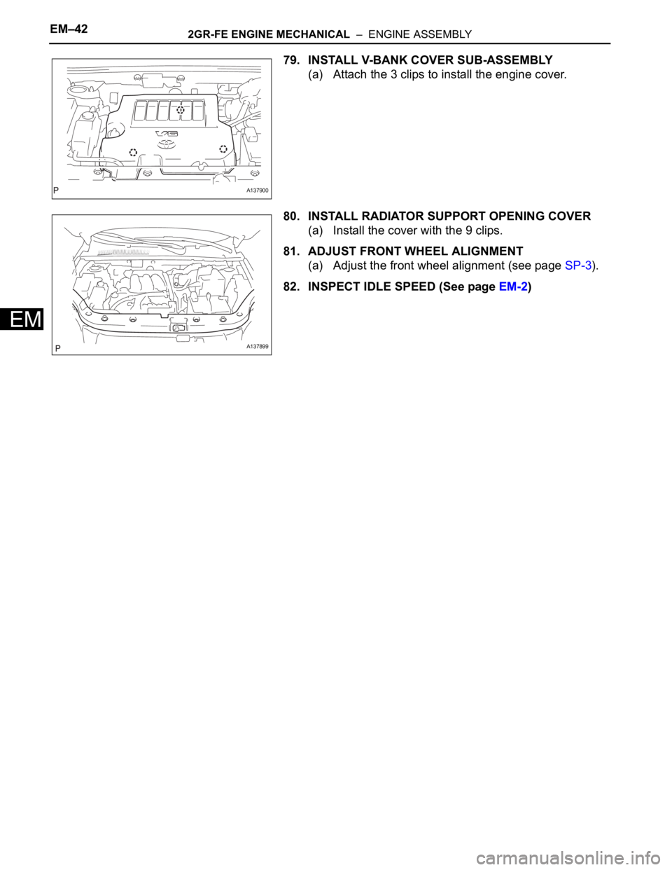
79. INSTALL V-BANK COVER SUB-ASSEMBLY
(a) Attach the 3 clips to install the engine cover.
80. INSTALL RADIATOR SUPPORT OPENING COVER
(a) Install the cover with the 9 clips.
81. ADJUST FRONT WHEEL ALIGNMENT
(a) Adjust the front wheel alignment (see page SP-3).
82. INSPECT IDLE SPEED (See page EM-2)
A137900
A137899
Page 859 of 2000
2GR-FE COOLING – THERMOSTATCO–19
CO
REMOVAL
1. REMOVE FRONT WHEEL RH
2. REMOVE NO. 1 ENGINE UNDER COVER (See page
EM-21)
3. REMOVE ENGINE UNDER COVER REAR RH (See
page EM-21)
4. REMOVE FRONT SUSPENSION MEMBER
REINFORCEMENT RH (See page EM-7)
5. DRAIN ENGINE COOLANT (See page CO-8)
6. REMOVE V-BANK COVER SUB-ASSEMBLY (See
page EM-21)
7. REMOVE RADIATOR SUPPORT OPENING COVER
(See page EM-22)
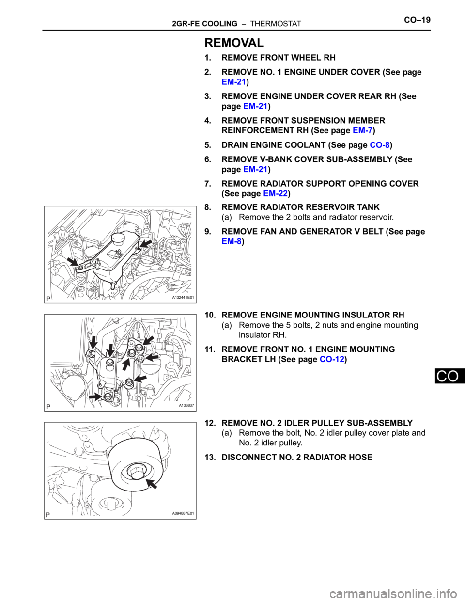
8. REMOVE RADIATOR RESERVOIR TANK
(a) Remove the 2 bolts and radiator reservoir.
9. REMOVE FAN AND GENERATOR V BELT (See page
EM-8)
10. REMOVE ENGINE MOUNTING INSULATOR RH
(a) Remove the 5 bolts, 2 nuts and engine mounting
insulator RH.
11. REMOVE FRONT NO. 1 ENGINE MOUNTING
BRACKET LH (See page CO-12)
12. REMOVE NO. 2 IDLER PULLEY SUB-ASSEMBLY
(a) Remove the bolt, No. 2 idler pulley cover plate and
No. 2 idler pulley.
13. DISCONNECT NO. 2 RADIATOR HOSE
A132441E01
A136837
A094887E01
Page 862 of 2000
CO–222GR-FE COOLING – THERMOSTAT
CO
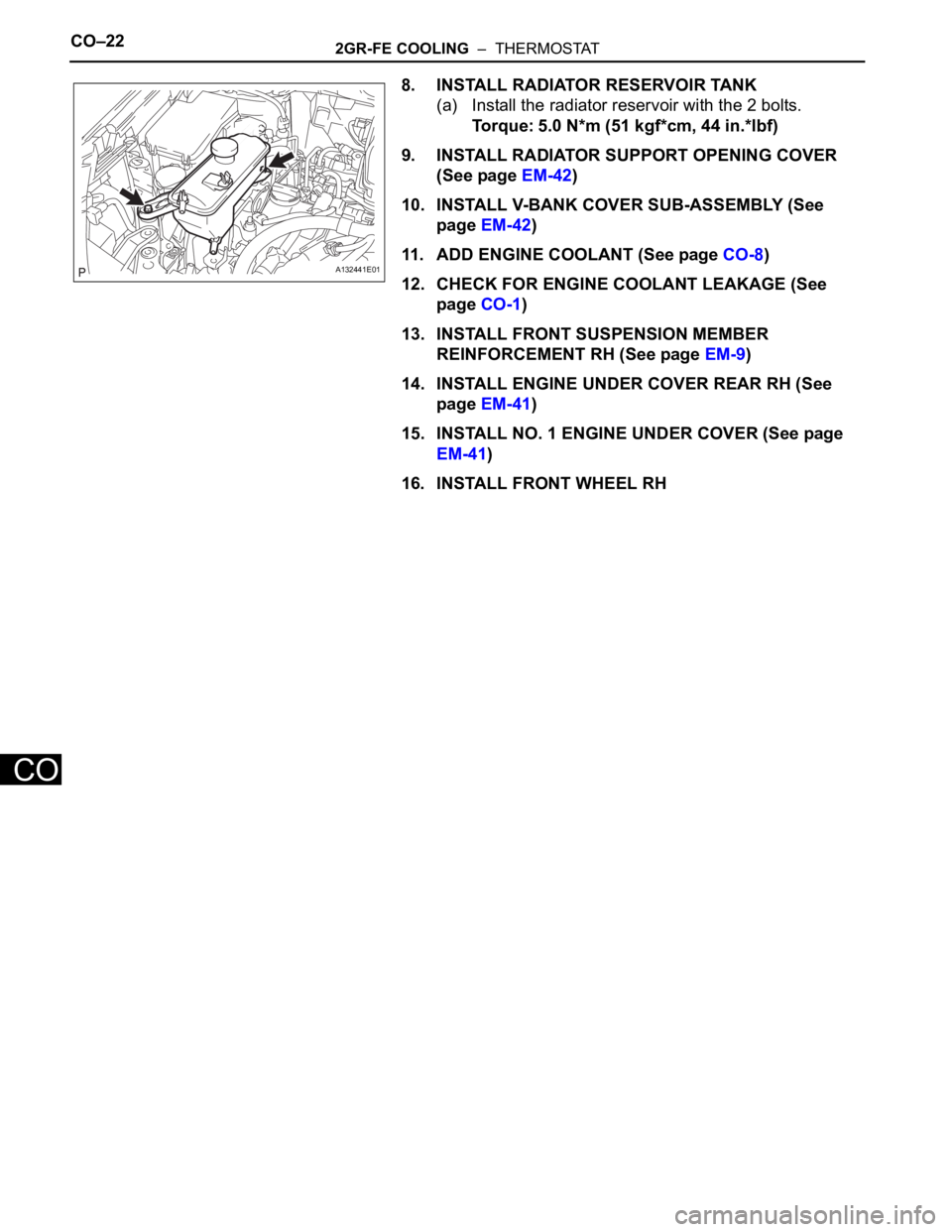
8. INSTALL RADIATOR RESERVOIR TANK
(a) Install the radiator reservoir with the 2 bolts.
Torque: 5.0 N*m (51 kgf*cm, 44 in.*lbf)
9. INSTALL RADIATOR SUPPORT OPENING COVER
(See page EM-42)
10. INSTALL V-BANK COVER SUB-ASSEMBLY (See
page EM-42)
11. ADD ENGINE COOLANT (See page CO-8)
12. CHECK FOR ENGINE COOLANT LEAKAGE (See
page CO-1)
13. INSTALL FRONT SUSPENSION MEMBER
REINFORCEMENT RH (See page EM-9)
14. INSTALL ENGINE UNDER COVER REAR RH (See
page EM-41)
15. INSTALL NO. 1 ENGINE UNDER COVER (See page
EM-41)
16. INSTALL FRONT WHEEL RH
A132441E01
Page 931 of 2000
CH–122GR-FE CHARGING – GENERATOR
CH
REMOVAL
1. REMOVE RADIATOR ASSEMBLY
(a) Remove the radiator (see page CO-36).
2. REMOVE FRONT WHEEL RH
3. REMOVE ENGINE UNDER COVER REAR RH (See
page EM-21)
4. REMOVE FRONT SUSPENSION MEMBER
REINFORCEMENT RH (See page EM-7)
5. REMOVE RADIATOR RESERVOIR TANK (See page
CO-19)
6. REMOVE FAN AND GENERATOR V BELT (See page
EM-8)
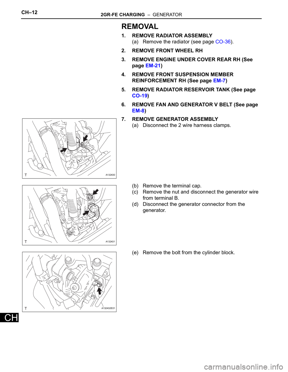
7. REMOVE GENERATOR ASSEMBLY
(a) Disconnect the 2 wire harness clamps.
(b) Remove the terminal cap.
(c) Remove the nut and disconnect the generator wire
from terminal B.
(d) Disconnect the generator connector from the
generator.
(e) Remove the bolt from the cylinder block.
A132430
A132431
A132432E01
Page 939 of 2000
CH–202GR-FE CHARGING – GENERATOR
CH
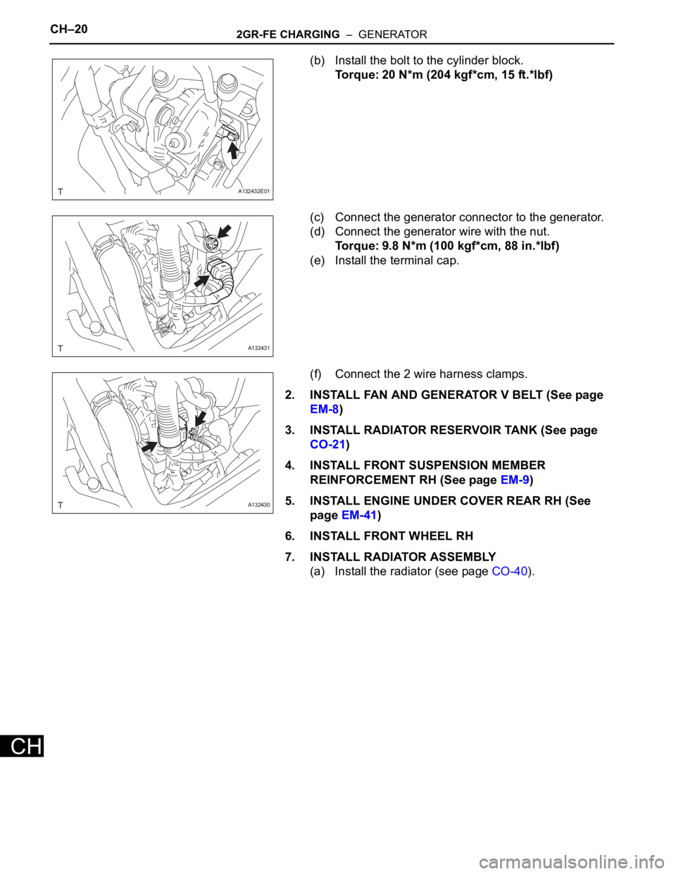
(b) Install the bolt to the cylinder block.
Torque: 20 N*m (204 kgf*cm, 15 ft.*lbf)
(c) Connect the generator connector to the generator.
(d) Connect the generator wire with the nut.
Torque: 9.8 N*m (100 kgf*cm, 88 in.*lbf)
(e) Install the terminal cap.
(f) Connect the 2 wire harness clamps.
2. INSTALL FAN AND GENERATOR V BELT (See page
EM-8)
3. INSTALL RADIATOR RESERVOIR TANK (See page
CO-21)
4. INSTALL FRONT SUSPENSION MEMBER
REINFORCEMENT RH (See page EM-9)
5. INSTALL ENGINE UNDER COVER REAR RH (See
page EM-41)
6. INSTALL FRONT WHEEL RH
7. INSTALL RADIATOR ASSEMBLY
(a) Install the radiator (see page CO-40).
A132432E01
A132431
A132430
Page 952 of 2000

AX–18U140F AUTOMATIC TRANSAXLE – AUTOMATIC TRANSAXLE SYSTEM
AX
MECHANICAL SYSTEM TESTS
1. STALL SPEED TEST
HINT:
This test is to check the overall performance of the
engine and transaxle.
NOTICE:
• Do not perform the stall speed test longer than 5
seconds.
• To ensure safety, perform this test in an open and
level area that provides good traction.
• The stall speed test should always be performed
with at least 2 people. One person should observe
the condition of the wheels and wheel chocks
while the other is performing the test.
(a) Connect the intelligent tester to the CAN VIM. Then
connect the CAN VIM to the DLC3.
(b) Run the vehicle until the transmission fluid
temperature has reached 50 to 80
C (122 to 176F).
(c) Allow the engine to idle with the air conditioning
OFF.
(d) Chock all 4 wheels.
(e) Set the parking brake and keep the brake pedal
depressed firmly with your left foot.
(f) Move the shift lever to the D position.
(g) Depress the accelerator pedal as much as possible
with your right foot.
(h) Read the engine rpm (stall speed) and release the
accelerator pedal immediately.
Standard value:
2,150 to 2,450 rpm
Evaluation:
NOTICE:
Perform the test at the normal operating ATF
temperature of 50 to 80
C (122 to 176F).
2. SHIFT TIME LAG TEST
HINT:
This test is to check the condition of the direct clutch,
forward clutch, 1st brake and reverse brake.
(a) Connect the intelligent tester to the CAN VIM. Then
connect the CAN VIM to the DLC3.
(b) Run the vehicle until the transmission fluid
temperature has reached 50 to 80
C (122 to 176F).
(c) Allow the engine to idle with the air conditioning
OFF.
Test Result Possible Cause
Stall speed is lower than standard value • Stator one-way clutch is not operating properly
• Torque converter is faulty (stall speed is less than standard value
by 600 rpm or more)
• Engine power may be insufficient
Stall speed is higher than standard value • Line pressure is low
• C1 clutch slipping
• F3 one-way clutch is not operating properly
• F4 one-way clutch is not operating properly