wheel TOYOTA RAV4 2006 Service User Guide
[x] Cancel search | Manufacturer: TOYOTA, Model Year: 2006, Model line: RAV4, Model: TOYOTA RAV4 2006Pages: 2000, PDF Size: 45.84 MB
Page 195 of 2000
2AZ-FE ENGINE MECHANICAL – DRIVE BELTEM–7
EM
REMOVAL
1. REMOVE RADIATOR SUPPORT OPENING COVER
2. REMOVE FRONT WHEEL RH
3. REMOVE FRONT FENDER APRON RH
4. REMOVE FRONT SUSPENSION MEMBER
REINFORCEMENT RH
(a) Remove the 4 bolts and reinforcement RH.
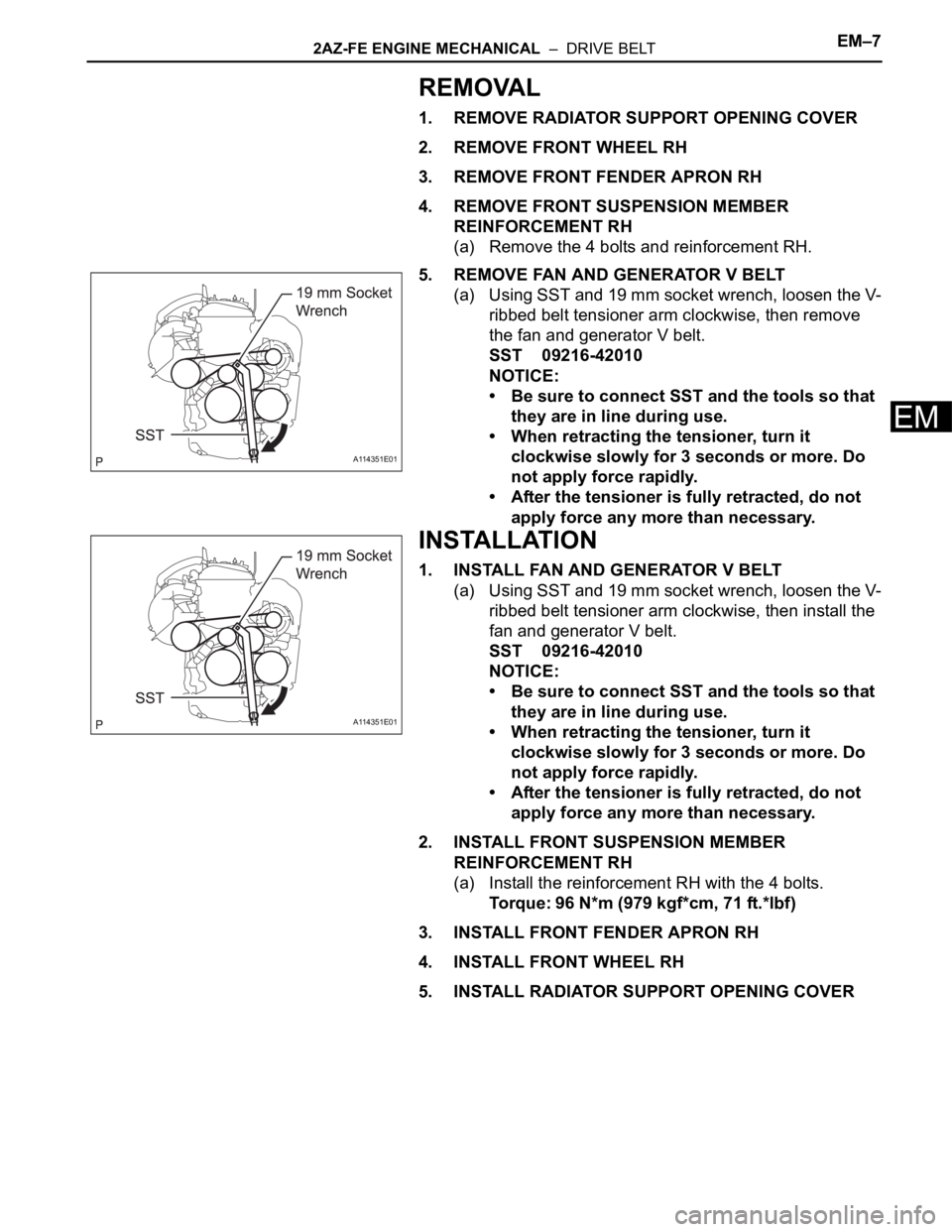
5. REMOVE FAN AND GENERATOR V BELT
(a) Using SST and 19 mm socket wrench, loosen the V-
ribbed belt tensioner arm clockwise, then remove
the fan and generator V belt.
SST 09216-42010
NOTICE:
• Be sure to connect SST and the tools so that
they are in line during use.
• When retracting the tensioner, turn it
clockwise slowly for 3 seconds or more. Do
not apply force rapidly.
• After the tensioner is fully retracted, do not
apply force any more than necessary.
INSTALLATION
1. INSTALL FAN AND GENERATOR V BELT
(a) Using SST and 19 mm socket wrench, loosen the V-
ribbed belt tensioner arm clockwise, then install the
fan and generator V belt.
SST 09216-42010
NOTICE:
• Be sure to connect SST and the tools so that
they are in line during use.
• When retracting the tensioner, turn it
clockwise slowly for 3 seconds or more. Do
not apply force rapidly.
• After the tensioner is fully retracted, do not
apply force any more than necessary.
2. INSTALL FRONT SUSPENSION MEMBER
REINFORCEMENT RH
(a) Install the reinforcement RH with the 4 bolts.
Torque: 96 N*m (979 kgf*cm, 71 ft.*lbf)
3. INSTALL FRONT FENDER APRON RH
4. INSTALL FRONT WHEEL RH
5. INSTALL RADIATOR SUPPORT OPENING COVER
A114351E01
A114351E01
Page 199 of 2000

EM–242GR-FE ENGINE MECHANICAL – ENGINE ASSEMBLY
EM
(b) 4WD:
Disconnect the control cable (see page AX-154).
31. REMOVE FRONT EXHAUST PIPE ASSEMBLY (See
page EX-3)
32. REMOVE CENTER EXHAUST PIPE ASSEMBLY (See
page EX-2)
33. REMOVE PROPELLER WITH CENTER BEARING
SHAFT ASSEMBLY (See page PR-3)
34. REMOVE FRONT WHEELS
35. REMOVE FRONT AXLE HUB NUT LH
(a) Remove the hub nut (see page AH-8).
36. REMOVE FRONT AXLE HUB NUT RH
(a) Remove the hub nut (see page AH-8).
37. DISCONNECT FRONT STABILIZER LINK ASSEMBLY
LH (See page SP-30)
38. DISCONNECT FRONT STABILIZER LINK ASSEMBLY
RH (See page SP-30)
39. DISCONNECT STEERING INTERMEDIATE SHAFT
(See page PS-44)
40. DISCONNECT TIE ROD END SUB-ASSEMBLY RH
(See page PS-42)
41. DISCONNECT TIE ROD END SUB-ASSEMBLY LH
(See page PS-42)
42. REMOVE FRONT DRIVE SHAFT LH
(a) 2WD:
Remove the drive shaft (see page DS-10).
(b) 4WD:
Remove the drive shaft (see page DS-43).
43. REMOVE FRONT DRIVE SHAFT RH
(a) 2WD:
Remove the drive shaft (see page DS-10).
(b) 4WD:
Remove the drive shaft (see page DS-43).
44. REMOVE ENGINE WITH TRANSAXLE
(a) Install the No. 1 and No. 2 engine hangers with the
4 bolts as shown in the illustration.
Torque: 33 N*m (337 kgf*cm, 24 ft.*lbf)
HINT:
• Insert the claw of the hanger into hole of the
cylinder head.
• Fit the fork part of the hanger onto the rib of the
cylinder head.
A129635E02
Part Name Part No.
No. 1 engine hanger 12281-31120
No. 2 engine hanger 12282-31100
Bolt 91671-10825
Page 333 of 2000

PREPARATION – SUPPLEMENTAL RESTRAINT SYSTEMPP–85
PP
EQUIPMENT
Bolt
Length: 35.0 mm (1.378 in.)
Pitch: 1.0 mm (0.039 in.)
Diameter: 6.0 mm (0.236 in.)Airbag disposal
Plastic bag Airbag disposal
Tire
Width: 185 mm (7.28 in.)
Inner diameter: 360 mm (14.17 in.)Airbag disposal
Tire with disc wheel
Width: 185 mm (7.28 in.)
Inner diameter: 360 mm (14.17 in.)Airbag disposal
Torque wrench -
Page 386 of 2000

SERVICE SPECIFICATIONS – U151F AUTOMATIC TRANSMISSIONSS–53
SS
TORQUE SPECIFICATIONS
Automatic Transaxle Assembly
Part Tightened N*m kgf*cm ft*lbf
Park/neutral position switch Nut 6.9 70 61 in.*lbf
Bolt 5.4 55 48 in.*lbf
Control shaft lever x Control shaft 13 133 10
Shift control cable x Control shaft lever 15 153 11
Transaxle housing x Engine block Upper side
bolt64 653 47
Lower side
bolt A37 377 27
Lower side
bolt B46 470 34
Torque converter clutch x Drive plate 41 418 30
Flywheel housing under cover x Automatic transaxle 7.8 80 69 in.*lbf
Front engine mounting bracket x Transaxle 64 653 47
Rear engine mounting bracket x Transaxle 45 459 33
Engine mounting bracket LH x Transaxle 64 653 47
Oil filler tube x Transaxle
Oil filler tube x Front engine mounting bracket5.5 56 49 in.*lbf
Control cable bracket No. 1 x Transaxle 12 122 9
Control cable bracket No. 2 x Transaxle 12 122 9
Oil cooler inlet elbow x Transaxle 27 276 20
Oil cooler outlet elbow x Transaxle 27 276 20
Starter x Transaxle37 377 27
Starter wire x Starter9.8 100 88 in.*lbf
Speed sensor (NC) x Transaxle11 11 2 8
Speed sensor (NT) x Transaxle11 11 2 8
Drain plug x Oil pan47 479 35
Transmission wire x Transaxle5.4 55 48 in.*lbf
ATF temperature sensor x Valve body 6.6 67 58 in.*lbf
Oil pan x Transaxle7.8 80 69 in.*lbf
Solenoid valve x Valve body SL2, DSL,
S411 11 0 8
SL1, SL3 6.6 67 58 in.*lbf
Valve body x Transaxle11 11 2 8
Oil strainer x Valve body11 11 2 8
Floor shift assembly x Body12 122 9
Control cable clamp x Engine mounting insulator 12 122 9
Differential gear lube apply tube x Transaxle housing 9.8 100 87 in.*lbf
Front planetary gear lock nut280 3,355 207
Brake apply tube clamp x Transaxle case 5.4 55 48 in.*lbf
Transaxle case No. 1 plug x Transaxle rear cover 7.4 75 65 in.*lbf
Transaxle rear cover x Transaxle case Bolt A 19 194 14
Other bolt 25 255 18
Parking lock pawl shaft x Transaxle case 9.8 100 87 in.*lbf
Oil pump assembly x Transaxle case 22 226 16
Transaxle housing x Transaxle case Bolt A 22 254 16
Bolt B 29 295 21
Bolt C 29 295 21
Bolt D 22 254 16
Automatic transmission case plug x Transaxle housing 7.4 75 65 in.*lbf
Page 393 of 2000
SS–72SERVICE SPECIFICATIONS – DRIVE SHAFT
SS
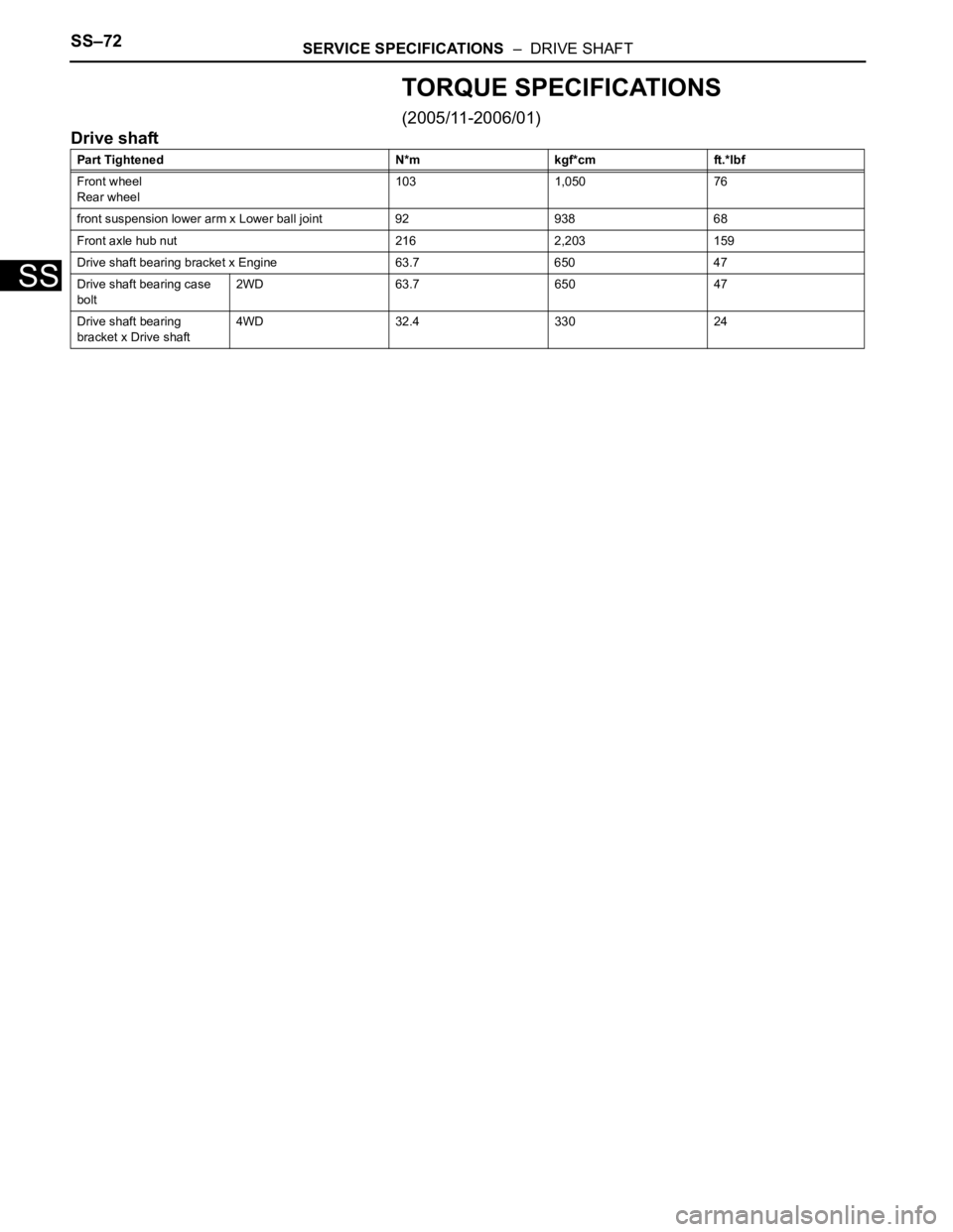
TORQUE SPECIFICATIONS
(2005/11-2006/01)
Drive shaft
Part Tightened N*m kgf*cm ft.*lbf
Front wheel
Rear wheel103 1,050 76
front suspension lower arm x Lower ball joint 92 938 68
Front axle hub nut 216 2,203 159
Drive shaft bearing bracket x Engine 63.7 650 47
Drive shaft bearing case
bolt2WD 63.7 650 47
Drive shaft bearing
bracket x Drive shaft4WD 32.4 330 24
Page 394 of 2000

SERVICE SPECIFICATIONS – DRIVE SHAFTSS–73
SS
TORQUE SPECIFICATIONS
(2006/01- )
Drive shaft
Part Tightened N*m kgf*cm ft.*lbf
Front wheel
Rear wheel103 1,050 76
front suspension lower arm x Lower ball joint 92 938 68
Front axle hub nut
26 216 2,203 159
30 292 2,978 215
Drive shaft bearing bracket x Engine 63.7 650 47
Drive shaft bearing case
bolt2WD 63.7 650 47
Drive shaft bearing
bracket x Drive shaft4WD 32.4 330 24
Page 403 of 2000
AH–6AXLE – FRONT AXLE HUB
AH
ON-VEHICLE INSPECTION
1. CHECK FRONT AXLE HUB BEARING
(a) Remove the front wheel.
(b) Disconnect the front disc brake cylinder (see page
BR-40).
(c) Remove the front disc.
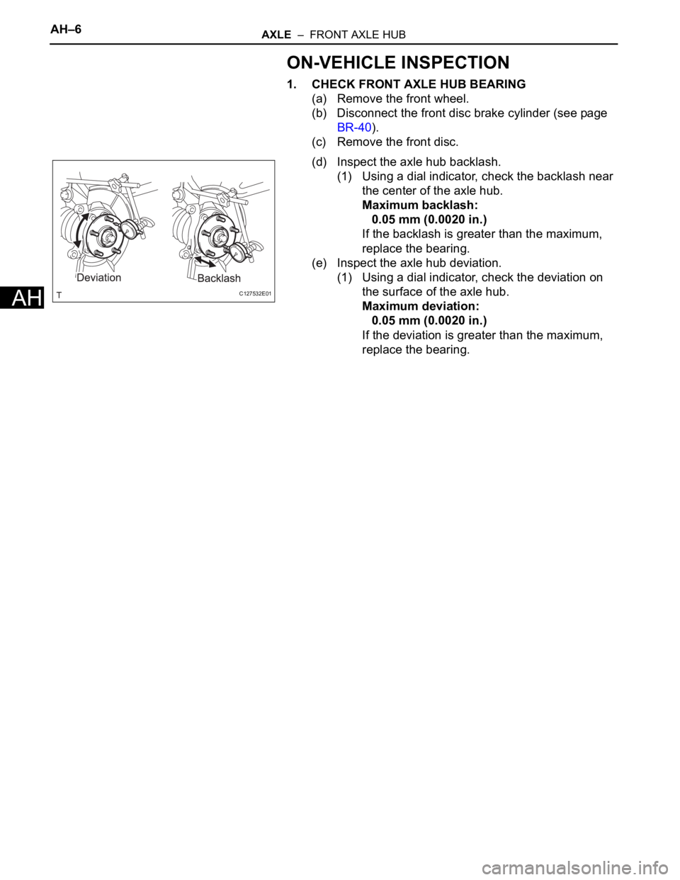
(d) Inspect the axle hub backlash.
(1) Using a dial indicator, check the backlash near
the center of the axle hub.
Maximum backlash:
0.05 mm (0.0020 in.)
If the backlash is greater than the maximum,
replace the bearing.
(e) Inspect the axle hub deviation.
(1) Using a dial indicator, check the deviation on
the surface of the axle hub.
Maximum deviation:
0.05 mm (0.0020 in.)
If the deviation is greater than the maximum,
replace the bearing.
C127532E01
Page 404 of 2000
AXLE – FRONT AXLE HUBAH–7
AH
REMOVAL
(2005/11-2006/01)
HINT:
• Use the same procedures for the RH side and LH side.
• The procedures listed below are for the LH side.
1. REMOVE FRONT WHEEL
2. DRAIN AUTOMATIC TRANSAXLE FLUID
(a) Drain the automatic transaxle fluid for U140F (see
page AX-147).
(b) Drain the automatic transaxle fluid for U241E (see
page AX-146).
3. DISCONNECT CABLE FROM NEGATIVE BATTERY
TERMINAL
CAUTION:
Wait at least 90 seconds after disconnecting the
cable from the negative (-) battery terminal to
prevent airbag and seat belt pretensioner activation.
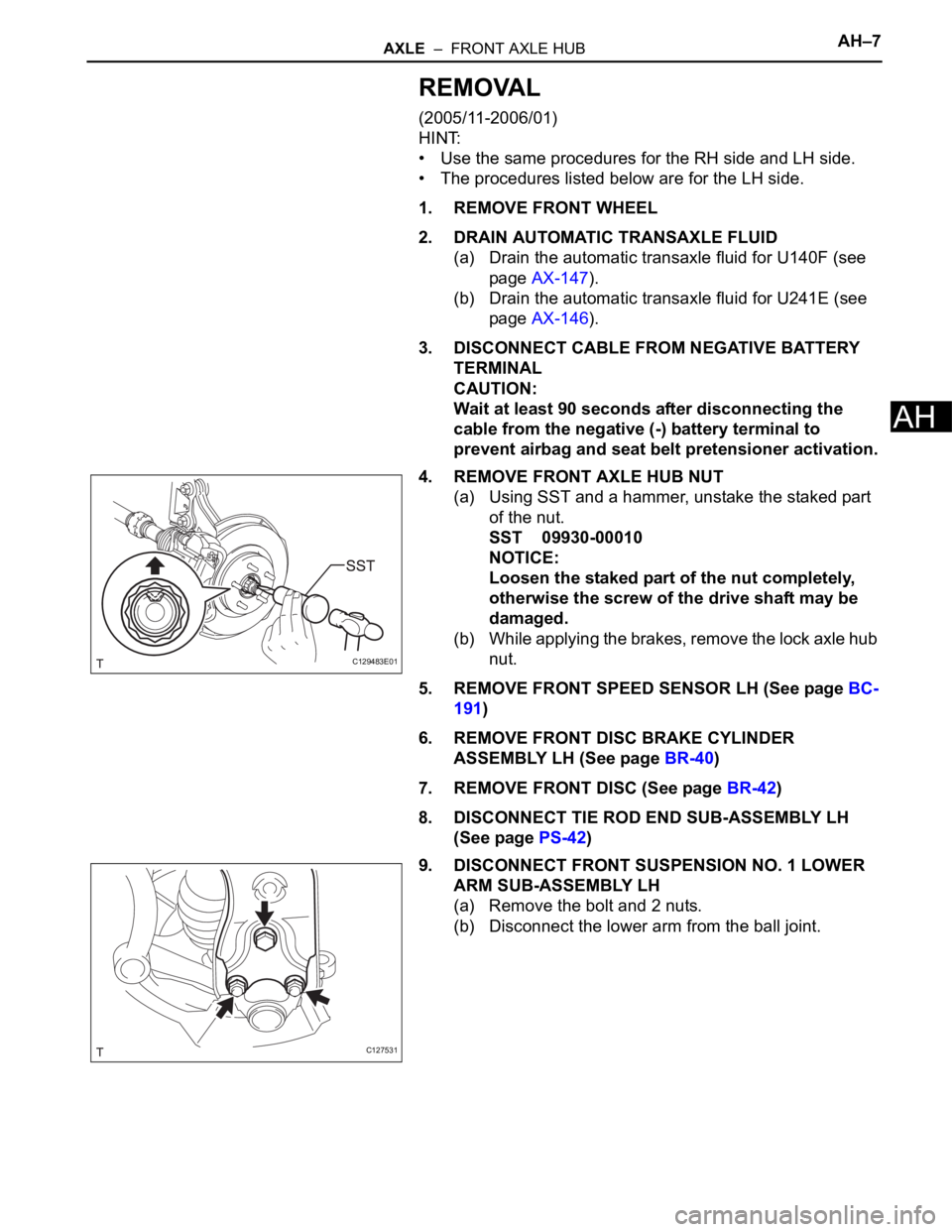
4. REMOVE FRONT AXLE HUB NUT
(a) Using SST and a hammer, unstake the staked part
of the nut.
SST 09930-00010
NOTICE:
Loosen the staked part of the nut completely,
otherwise the screw of the drive shaft may be
damaged.
(b) While applying the brakes, remove the lock axle hub
nut.
5. REMOVE FRONT SPEED SENSOR LH (See page BC-
191)
6. REMOVE FRONT DISC BRAKE CYLINDER
ASSEMBLY LH (See page BR-40)
7. REMOVE FRONT DISC (See page BR-42)
8. DISCONNECT TIE ROD END SUB-ASSEMBLY LH
(See page PS-42)
9. DISCONNECT FRONT SUSPENSION NO. 1 LOWER
ARM SUB-ASSEMBLY LH
(a) Remove the bolt and 2 nuts.
(b) Disconnect the lower arm from the ball joint.
C129483E01
C127531
Page 411 of 2000
TW–4TIRE AND WHEEL – TIRE PRESSURE WARNING SYSTEM
TW
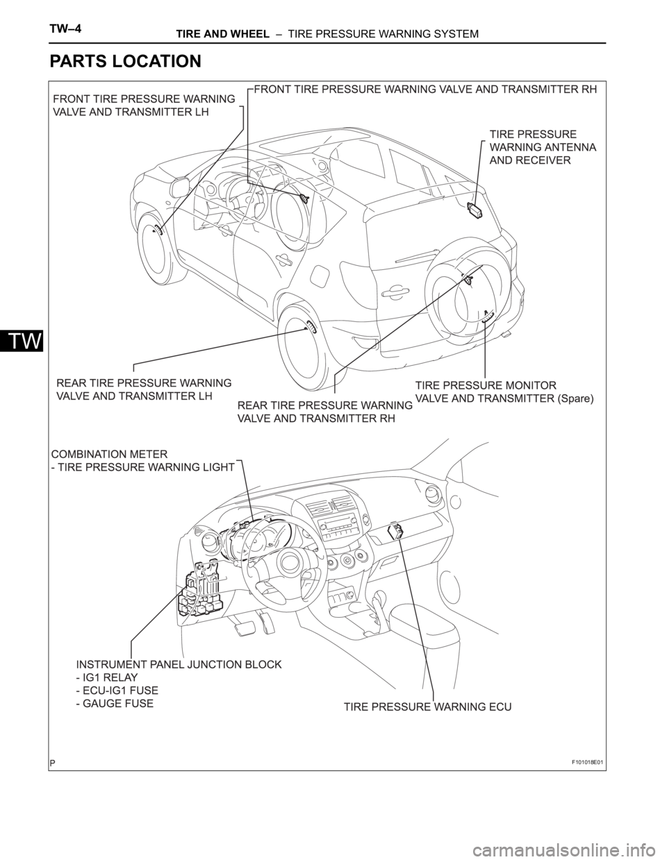
PARTS LOCATION
F101018E01
Page 412 of 2000
TIRE AND WHEEL – TIRE PRESSURE WARNING SYSTEMTW–5
TW
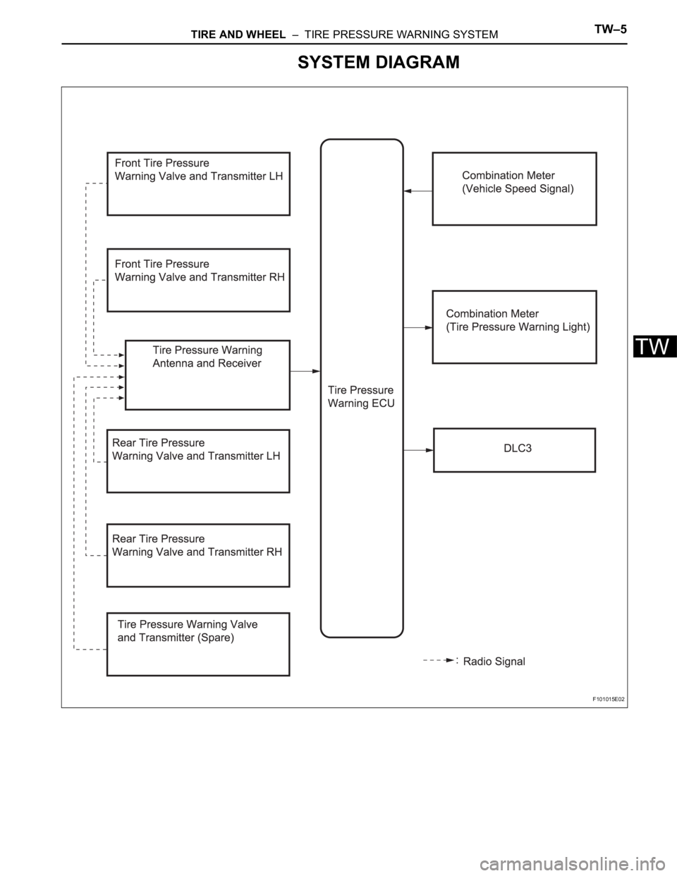
SYSTEM DIAGRAM
F101015E02