relay TOYOTA RAV4 2006 Service Service Manual
[x] Cancel search | Manufacturer: TOYOTA, Model Year: 2006, Model line: RAV4, Model: TOYOTA RAV4 2006Pages: 2000, PDF Size: 45.84 MB
Page 1619 of 2000
POWER STEERING – ELECTRONIC POWER STEERING SYSTEMPS–19
PS
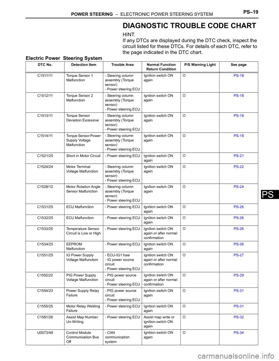
DIAGNOSTIC TROUBLE CODE CHART
HINT:
If any DTCs are displayed during the DTC check, inspect the
circuit listed for these DTCs. For details of each DTC, refer to
the page indicated in the DTC chart.
Electric Power Steering System
DTC No. Detection Item Trouble Area Normal Function
Return ConditionP/S Warning Light See page
C1511/11 Torque Sensor 1
Malfunction- Steering column
assembly (Torque
sensor)
- Power steering ECUIgnition switch ON
again
PS-18
C1512/11 Torque Sensor 2
Malfunction- Steering column
assembly (Torque
sensor)
- Power steering ECUIgnition switch ON
again
PS-18
C1513/11 Torque Sensor
Deviation Excessive- Steering column
assembly (Torque
sensor)
- Power steering ECUIgnition switch ON
again
PS-18
C1514/11 Torque Sensor Power
Supply Voltage
Malfunction- Steering column
assembly (Torque
sensor)
- Power steering ECUIgnition switch ON
again
PS-18
C1521/25 Short in Motor Circuit - Power steering ECU Ignition switch ON
again
PS-21
C1524/24 Motor Terminal
Voltage Malfunction- Steering column
assembly (Torque
sensor)
- Power steering ECUIgnition switch ON
again
PS-22
C1528/12 Motor Rotation Angle
Sensor Malfunction- Steering column
assembly (Torque
sensor)
- Power steering ECUIgnition switch ON
again
PS-24
C1531/25 ECU Malfunction - Power steering ECU Ignition switch ON
again
PS-26
C1532/25 ECU Malfunction - Power steering ECU Ignition switch ON
again
PS-26
C1533/25 Temperature Sensor
Circuit is Low or High- Power steering ECU Ignition switch ON
again or after normal
confirmation
PS-26
C1534/25 EEPROM
Malfunction- Power steering ECU Ignition switch ON
again
PS-26
C1551/25 IG Power Supply
Voltage Malfunction- ECU-IG1 fuse
- IG power source
circuit
- Power steering ECUIgnition switch ON
again or after normal
confirmation
PS-27
C1552/22 PIG Power Supply
Voltage Malfunction- PIG power source
circuit
- Power steering ECUIgnition switch ON
again or after normal
confirmation
PS-29
C1554/23 Power Supply Relay
Failure- PIG power source
circuit
- Power steering ECUIgnition switch ON
again
PS-31
C1555/25 Motor Relay Welding
Failure- Power steering ECU Ignition switch ON
again
PS-31
C1581/26 Assist Map Number
Un-Writing- Power steering ECU Assist map write or
ignition switch ON
again
PS-32
U0073/49 Control Module
Communication Bus
Off- CAN
communication
systemIgnition switch ON
again
PS-34
Page 1629 of 2000
POWER STEERING – ELECTRONIC POWER STEERING SYSTEMPS–29
PS
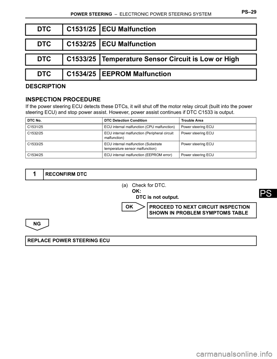
DESCRIPTION
INSPECTION PROCEDURE
If the power steering ECU detects these DTCs, it will shut off the motor relay circuit (built into the power
steering ECU) and stop power assist. However, power assist continues if DTC C1533 is output.
(a) Check for DTC.
OK:
DTC is not output.
OK
NG
DTC C1531/25 ECU Malfunction
DTC C1532/25 ECU Malfunction
DTC C1533/25 Temperature Sensor Circuit is Low or High
DTC C1534/25 EEPROM Malfunction
DTC No. DTC Detection Condition Trouble Area
C1531/25 ECU internal malfunction (CPU malfunction) Power steering ECU
C1532/25 ECU internal malfunction (Peripheral circuit
malfunction)Power steering ECU
C1533/25 ECU internal malfunction (Substrate
temperature sensor malfunction)Power steering ECU
C1534/25 ECU internal malfunction (EEPROM error) Power steering ECU
1RECONFIRM DTC
PROCEED TO NEXT CIRCUIT INSPECTION
SHOWN IN PROBLEM SYMPTOMS TABLE
REPLACE POWER STEERING ECU
Page 1632 of 2000
PS–32POWER STEERING – ELECTRONIC POWER STEERING SYSTEM
PS
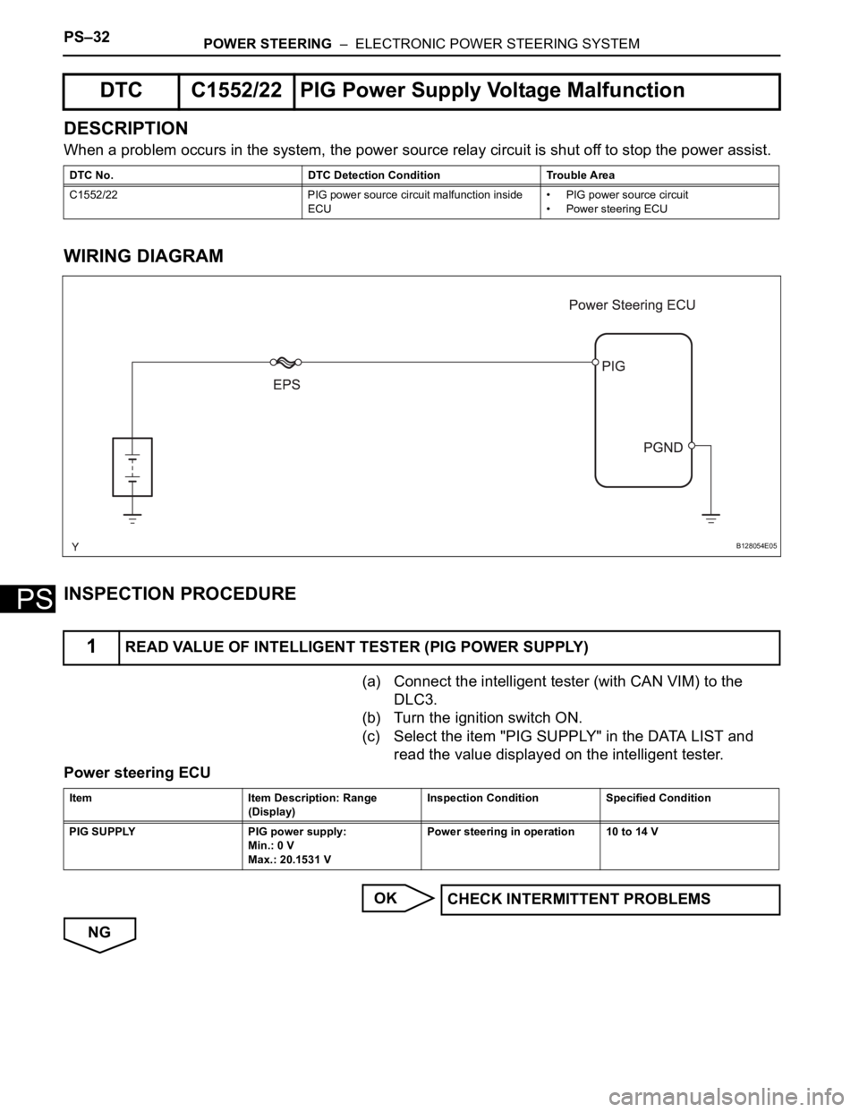
DESCRIPTION
When a problem occurs in the system, the power source relay circuit is shut off to stop the power assist.
WIRING DIAGRAM
INSPECTION PROCEDURE
(a) Connect the intelligent tester (with CAN VIM) to the
DLC3.
(b) Turn the ignition switch ON.
(c) Select the item "PIG SUPPLY" in the DATA LIST and
read the value displayed on the intelligent tester.
Power steering ECU
OK
NG
DTC C1552/22 PIG Power Supply Voltage Malfunction
DTC No. DTC Detection Condition Trouble Area
C1552/22 PIG power source circuit malfunction inside
ECU• PIG power source circuit
• Power steering ECU
1READ VALUE OF INTELLIGENT TESTER (PIG POWER SUPPLY)
B128054E05
Item Item Description: Range
(Display)Inspection Condition Specified Condition
PIG SUPPLY PIG power supply:
Min.: 0 V
Max.: 20.1531 VPower steering in operation 10 to 14 V
CHECK INTERMITTENT PROBLEMS
Page 1650 of 2000
AC–22AIR CONDITIONING – AIR CONDITIONING SYSTEM (for Automatic Air Conditioning Sys-
tem)
AC
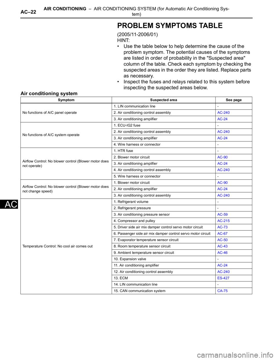
PROBLEM SYMPTOMS TABLE
(2005/11-2006/01)
HINT:
• Use the table below to help determine the cause of the
problem symptom. The potential causes of the symptoms
are listed in order of probability in the "Suspected area"
column of the table. Check each symptom by checking the
suspected areas in the order they are listed. Replace parts
as necessary.
• Inspect the fuses and relays related to this system before
inspecting the suspected areas below.
Air conditioning system
Symptom Suspected area See page
No functions of A/C panel operate1. LIN communication line -
2. Air conditioning control assemblyAC-240
3. Air conditioning amplifierAC-24
No functions of A/C system operate1. ECU-IG2 fuse -
2. Air conditioning control assemblyAC-240
3. Air conditioning amplifierAC-24
4. Wire harness or connector -
Airflow Control: No blower control (Blower motor does
not operate)1. HTR fuse -
2. Blower motor circuitAC-90
3. Air conditioning amplifierAC-24
4. Air conditioning control assemblyAC-240
5. Wire harness or connector -
Airflow Control: No blower control (Blower motor does
not change speed)1. Blower motor circuitAC-90
2. Air conditioning amplifierAC-24
3. Air conditioning control assemblyAC-240
Temperature Control: No cool air comes out1. Refrigerant volume -
2. Refrigerant pressure -
3. Air conditioning pressure sensorAC-59
4. Compressor and pulleyAC-215
5. Driver side air mix damper control servo motor circuitAC-73
6. Passenger side air mix damper control servo motor circuitAC-67
7. Evaporator temperature sensor circuitAC-50
8. Room temperature sensor circuitAC-43
9. Ambient temperature sensor circuitAC-46
10. Expansion valve -
11. Air conditioning amplifierAC-24
12. Air conditioning control assemblyAC-240
13. ECMES-427
14. LIN communication line -
15. CAN communication systemCA-75
Page 1652 of 2000
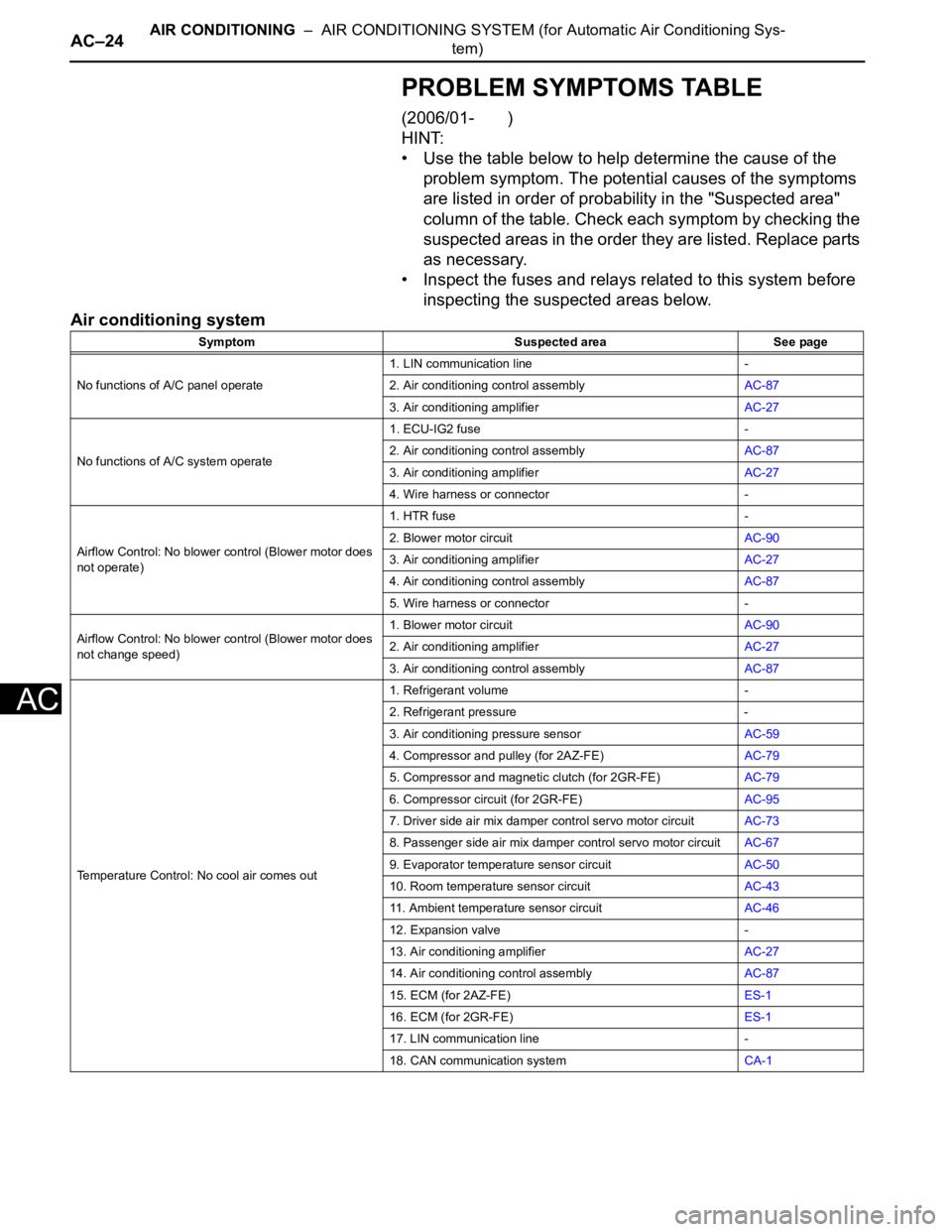
AC–24AIR CONDITIONING – AIR CONDITIONING SYSTEM (for Automatic Air Conditioning Sys-
tem)
AC
PROBLEM SYMPTOMS TABLE
(2006/01- )
HINT:
• Use the table below to help determine the cause of the
problem symptom. The potential causes of the symptoms
are listed in order of probability in the "Suspected area"
column of the table. Check each symptom by checking the
suspected areas in the order they are listed. Replace parts
as necessary.
• Inspect the fuses and relays related to this system before
inspecting the suspected areas below.
Air conditioning system
Symptom Suspected area See page
No functions of A/C panel operate1. LIN communication line -
2. Air conditioning control assemblyAC-87
3. Air conditioning amplifierAC-27
No functions of A/C system operate1. ECU-IG2 fuse -
2. Air conditioning control assemblyAC-87
3. Air conditioning amplifierAC-27
4. Wire harness or connector -
Airflow Control: No blower control (Blower motor does
not operate)1. HTR fuse -
2. Blower motor circuitAC-90
3. Air conditioning amplifierAC-27
4. Air conditioning control assemblyAC-87
5. Wire harness or connector -
Airflow Control: No blower control (Blower motor does
not change speed)1. Blower motor circuitAC-90
2. Air conditioning amplifierAC-27
3. Air conditioning control assemblyAC-87
Temperature Control: No cool air comes out1. Refrigerant volume -
2. Refrigerant pressure -
3. Air conditioning pressure sensorAC-59
4. Compressor and pulley (for 2AZ-FE)AC-79
5. Compressor and magnetic clutch (for 2GR-FE)AC-79
6. Compressor circuit (for 2GR-FE)AC-95
7. Driver side air mix damper control servo motor circuitAC-73
8. Passenger side air mix damper control servo motor circuitAC-67
9. Evaporator temperature sensor circuitAC-50
10. Room temperature sensor circuitAC-43
11. Ambient temperature sensor circuitAC-46
12. Expansion valve -
13. Air conditioning amplifierAC-27
14. Air conditioning control assemblyAC-87
15. ECM (for 2AZ-FE)ES-1
16. ECM (for 2GR-FE)ES-1
17. LIN communication line -
18. CAN communication systemCA-1
Page 1658 of 2000
AC–30AIR CONDITIONING – AIR CONDITIONING SYSTEM (for Automatic Air Conditioning Sys-
tem)
AC
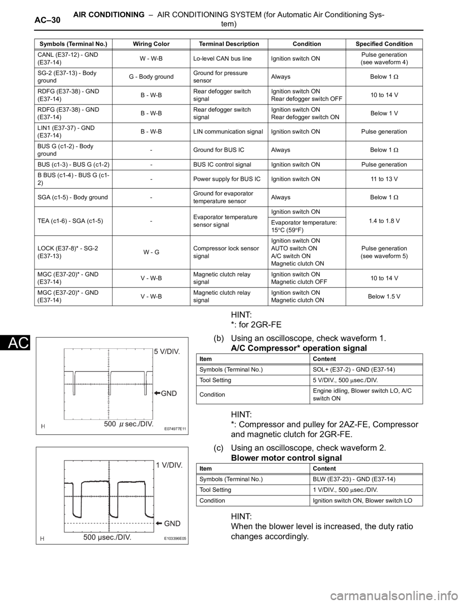
HINT:
*: for 2GR-FE
(b) Using an oscilloscope, check waveform 1.
A/C Compressor* operation signal
HINT:
*: Compressor and pulley for 2AZ-FE, Compressor
and magnetic clutch for 2GR-FE.
(c) Using an oscilloscope, check waveform 2.
Blower motor control signal
HINT:
When the blower level is increased, the duty ratio
changes accordingly.
CANL (E37-12) - GND
(E37-14)W - W-B Lo-level CAN bus line Ignition switch ONPulse generation
(see waveform 4)
SG-2 (E37-13) - Body
groundG - Body groundGround for pressure
sensorAlways Below 1
RDFG (E37-38) - GND
(E37-14)B - W-BRear defogger switch
signalIgnition switch ON
Rear defogger switch OFF10 to 14 V
RDFG (E37-38) - GND
(E37-14)B - W-BRear defogger switch
signalIgnition switch ON
Rear defogger switch ONBelow 1 V
LIN1 (E37-37) - GND
(E37-14)B - W-B LIN communication signal Ignition switch ON Pulse generation
BUS G (c1-2) - Body
ground- Ground for BUS IC Always Below 1
BUS (c1-3) - BUS G (c1-2) - BUS IC control signal Ignition switch ON Pulse generation
B BUS (c1-4) - BUS G (c1-
2)- Power supply for BUS IC Ignition switch ON 11 to 13 V
SGA (c1-5) - Body ground -Ground for evaporator
temperature sensorAlways Below 1
TEA (c1-6) - SGA (c1-5) -Evaporator temperature
sensor signalIgnition switch ON
1.4 to 1.8 V
Evaporator temperature:
15
C (59F)
LOCK (E37-8)* - SG-2
(E37-13)W - GCompressor lock sensor
signalIgnition switch ON
AUTO switch ON
A/C switch ON
Magnetic clutch ONPulse generation
(see waveform 5)
MGC (E37-20)* - GND
(E37-14)V - W-BMagnetic clutch relay
signalIgnition switch ON
Magnetic clutch OFF10 to 14 V
MGC (E37-20)* - GND
(E37-14)V - W-BMagnetic clutch relay
signalIgnition switch ON
Magnetic clutch ONBelow 1.5 V Symbols (Terminal No.) Wiring Color Terminal Description ConditionSpecified Condition
E074977E11
Item Content
Symbols (Terminal No.) SOL+ (E37-2) - GND (E37-14)
Tool Setting 5 V/DIV., 500
sec./DIV.
ConditionEngine idling, Blower switch LO, A/C
switch ON
E103396E05
Item Content
Symbols (Terminal No.) BLW (E37-23) - GND (E37-14)
Tool Setting 1 V/DIV., 500
sec./DIV.
Condition Ignition switch ON, Blower switch LO
Page 1689 of 2000
RS–40SUPPLEMENTAL RESTRAINT SYSTEM – AIRBAG SYSTEM
RS
3. SYMPTOM SIMULATION
HINT:
The most difficult case in troubleshooting is when no
problem symptoms occur. In such a case, a through
problem analysis must be carried out. A simulation of the
same or similar conditions and environment in which the
problem occurred in the customer's vehicle should be
carried out. No matter how much skill or experience a
technician has, troubleshooting without confirming the
problem symptoms will lead to important repairs being
overlooked and mistakes or delays.
This leads to a standstill in troubleshooting.
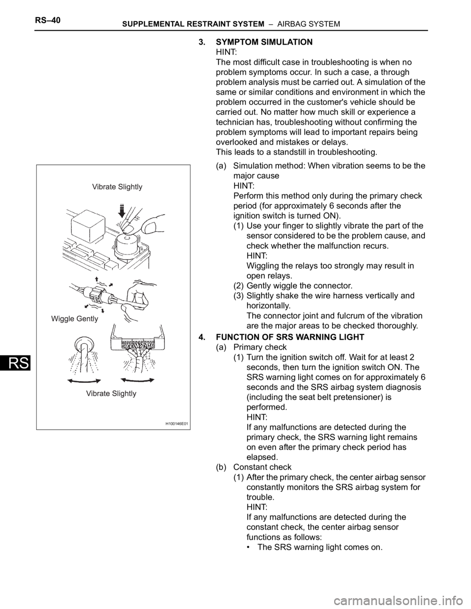
(a) Simulation method: When vibration seems to be the
major cause
HINT:
Perform this method only during the primary check
period (for approximately 6 seconds after the
ignition switch is turned ON).
(1) Use your finger to slightly vibrate the part of the
sensor considered to be the problem cause, and
check whether the malfunction recurs.
HINT:
Wiggling the relays too strongly may result in
open relays.
(2) Gently wiggle the connector.
(3) Slightly shake the wire harness vertically and
horizontally.
The connector joint and fulcrum of the vibration
are the major areas to be checked thoroughly.
4. FUNCTION OF SRS WARNING LIGHT
(a) Primary check
(1) Turn the ignition switch off. Wait for at least 2
seconds, then turn the ignition switch ON. The
SRS warning light comes on for approximately 6
seconds and the SRS airbag system diagnosis
(including the seat belt pretensioner) is
performed.
HINT:
If any malfunctions are detected during the
primary check, the SRS warning light remains
on even after the primary check period has
elapsed.
(b) Constant check
(1) After the primary check, the center airbag sensor
constantly monitors the SRS airbag system for
trouble.
HINT:
If any malfunctions are detected during the
constant check, the center airbag sensor
functions as follows:
• The SRS warning light comes on.
H100146E01
Page 1750 of 2000

SB–12SEAT BELT – SEAT BELT WARNING SYSTEM
SB
DATA LIST / ACTIVE TEST
1. ACTIVE TEST
HINT:
Performing the intelligent tester ACTIVE TEST allows
relay, VSV, actuator and other items to be operated
without removing any parts. Performing the ACTIVE
TEST early in troubleshooting is one way to save time.
The DATA LIST can be displayed during the ACTIVE
TEST.
(a) Connect the intelligent tester to the DLC3.
(b) Turn the ignition switch ON.
(c) Perform the ACTIVE TEST according to the display
on the tester.
Center airbag sensor:
Item Test Details Diagnostic Note
D-BELT REMIND D-SEAT BELT warning light (OFF / ON) Confirm that the vehicle is stopped, engine
idling
P-BELT REMIND P-SEAT BELT warning light (OFF / ON) Confirm that the vehicle is stopped, engine
idling
Page 1784 of 2000

ENGINE IMMOBILISER – ENGINE IMMOBILISER SYSTEMEI–13
EI
PROBLEM SYMPTOMS TABLE
HINT:
• Use the table below to help determine the cause of the
problem symptom. The potential causes of the symptoms
are listed in order of probability in the "Suspected area"
column of the table. Check each symptom by checking the
suspected areas in the order they are listed. Replace parts
as necessary.
• Inspect the fuses and relays related to this system before
inspecting the suspected areas below.
Engine immobiliser system:
HINT:
*1: for Manual air conditioning system
*2: for Automatic air conditioning system
Symptom Suspected area See page
Engine does not start1. ECU power source circuitEI-41
2. SFI systemES-24
Security indicator light malfunction1. Clock sub-assembly*1EI-38
2. Heater control panel*2EI-38
3. Transponder key ECUEI-38
Page 1793 of 2000

EI–22ENGINE IMMOBILISER – ENGINE IMMOBILISER SYSTEM
EI
2. PERFORM ACTIVE TEST
HINT:
Performing the intelligent tester's ACTIVE TEST allows
relay, VSV, actuator and other items to be operated
without removing any parts. Performing the ACTIVE
TEST early in troubleshooting is one way to save time.
The DATA LIST can be displayed during the ACTIVE
TEST.
(a) Connect the intelligent tester (with CAN VIM) to the
DLC3.
(b) Turn the ignition switch ON and turn the tester ON.
(c) Select the following menu items: DIAGNOSIS /
OBD/MOBD / IMMOBILISER / ACTIVE TEST.
(d) Perform the ACTIVE TEST by referring to the table
below.
Transponder key ECU:
+B+B judgment / NORMAL or
BREAKNORMAL: Battery supply is
normal
BREAK: Battery supply is
malfunctioning-
ANTENNA COILTransponder key coil condition /
NORMAL or FAILNORMAL: Transponder key coil
is normal
FAIL: Transponder key coil is
malfunctioning- ItemMeasurement Item / Display
(Range)Normal Condition Diagnostic Note
Item Test Details Diagnostic Note
SECURITY INDIC Turns security indicator light / ON or OFF -