Install air manifold TOYOTA RAV4 2006 Service Repair Manual
[x] Cancel search | Manufacturer: TOYOTA, Model Year: 2006, Model line: RAV4, Model: TOYOTA RAV4 2006Pages: 2000, PDF Size: 45.84 MB
Page 630 of 2000
EM–862AZ-FE ENGINE MECHANICAL – CYLINDER HEAD
EM
22. INSTALL ENGINE MOUNTING INSULATOR RH (See
page EM-41)
23. INSTALL RADIATOR RESERVOIR (See page EM-112)
24. INSTALL GENERATOR ASSEMBLY (See page CH-15)
25. INSTALL FAN AND GENERATOR V BELT (See page
EM-7)
26. INSTALL FRONT SUSPENSION MEMBER
REINFORCEMENT RH (See page EM-7)
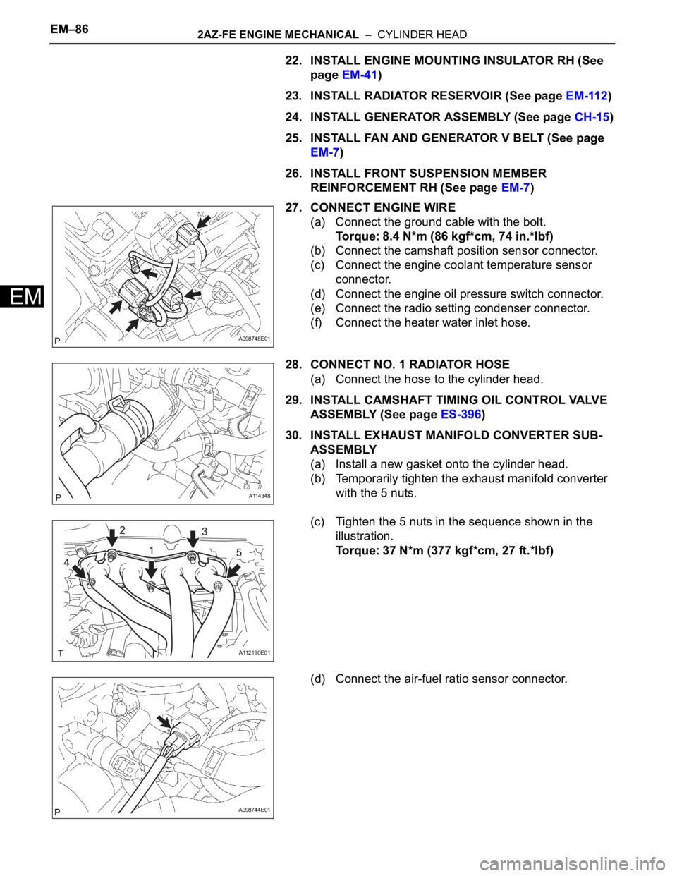
27. CONNECT ENGINE WIRE
(a) Connect the ground cable with the bolt.
Torque: 8.4 N*m (86 kgf*cm, 74 in.*lbf)
(b) Connect the camshaft position sensor connector.
(c) Connect the engine coolant temperature sensor
connector.
(d) Connect the engine oil pressure switch connector.
(e) Connect the radio setting condenser connector.
(f) Connect the heater water inlet hose.
28. CONNECT NO. 1 RADIATOR HOSE
(a) Connect the hose to the cylinder head.
29. INSTALL CAMSHAFT TIMING OIL CONTROL VALVE
ASSEMBLY (See page ES-396)
30. INSTALL EXHAUST MANIFOLD CONVERTER SUB-
ASSEMBLY
(a) Install a new gasket onto the cylinder head.
(b) Temporarily tighten the exhaust manifold converter
with the 5 nuts.
(c) Tighten the 5 nuts in the sequence shown in the
illustration.
Torque: 37 N*m (377 kgf*cm, 27 ft.*lbf)
(d) Connect the air-fuel ratio sensor connector.
A098748E01
A114348
A112190E01
A098744E01
Page 631 of 2000
2AZ-FE ENGINE MECHANICAL – CYLINDER HEADEM–87
EM
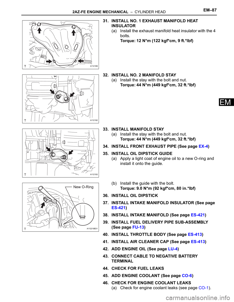
31. INSTALL NO. 1 EXHAUST MANIFOLD HEAT
INSULATOR
(a) Install the exhaust manifold heat insulator with the 4
bolts.
Torque: 12 N*m (122 kgf*cm, 9 ft.*lbf)
32. INSTALL NO. 2 MANIFOLD STAY
(a) Install the stay with the bolt and nut.
Torque: 44 N*m (449 kgf*cm, 32 ft.*lbf)
33. INSTALL MANIFOLD STAY
(a) Install the stay with the bolt and nut.
Torque: 44 N*m (449 kgf*cm, 32 ft.*lbf)
34. INSTALL FRONT EXHAUST PIPE (See page EX-4)
35. INSTALL OIL DIPSTICK GUIDE
(a) Apply a light coat of engine oil to a new O-ring and
install it onto the guide.
(b) Install the guide with the bolt.
Torque: 9.0 N*m (92 kgf*cm, 80 in.*lbf)
36. INSTALL OIL DIPSTICK
37. INSTALL INTAKE MANIFOLD INSULATOR (See page
ES-421)
38. INSTALL INTAKE MANIFOLD (See page ES-421)
39. INSTALL FUEL DELIVERY PIPE SUB-ASSEMBLY
(See page FU-13)
40. INSTALL THROTTLE BODY (See page ES-413)
41. INSTALL AIR CLEANER CAP (See page ES-413)
42. ADD ENGINE OIL (See page LU-4)
43. CONNECT CABLE TO NEGATIVE BATTERY
TERMINAL
44. CHECK FOR FUEL LEAKS
45. ADD ENGINE COOLANT (See page CO-6)
46. CHECK FOR ENGINE COOLANT LEAKS
(a) Check for engine coolant leaks (see page CO-1).
A112189
A112192
A112193
A112218E01
Page 646 of 2000
2AZ-FE ENGINE MECHANICAL – ENGINE ASSEMBLYEM–111
EM
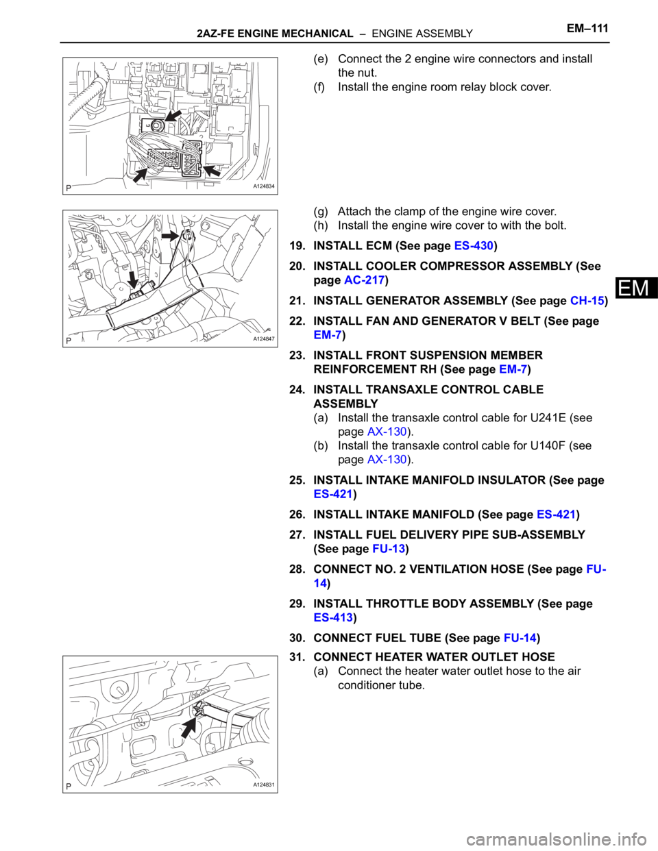
(e) Connect the 2 engine wire connectors and install
the nut.
(f) Install the engine room relay block cover.
(g) Attach the clamp of the engine wire cover.
(h) Install the engine wire cover to with the bolt.
19. INSTALL ECM (See page ES-430)
20. INSTALL COOLER COMPRESSOR ASSEMBLY (See
page AC-217)
21. INSTALL GENERATOR ASSEMBLY (See page CH-15)
22. INSTALL FAN AND GENERATOR V BELT (See page
EM-7)
23. INSTALL FRONT SUSPENSION MEMBER
REINFORCEMENT RH (See page EM-7)
24. INSTALL TRANSAXLE CONTROL CABLE
ASSEMBLY
(a) Install the transaxle control cable for U241E (see
page AX-130).
(b) Install the transaxle control cable for U140F (see
page AX-130).
25. INSTALL INTAKE MANIFOLD INSULATOR (See page
ES-421)
26. INSTALL INTAKE MANIFOLD (See page ES-421)
27. INSTALL FUEL DELIVERY PIPE SUB-ASSEMBLY
(See page FU-13)
28. CONNECT NO. 2 VENTILATION HOSE (See page FU-
14)
29. INSTALL THROTTLE BODY ASSEMBLY (See page
ES-413)
30. CONNECT FUEL TUBE (See page FU-14)
31. CONNECT HEATER WATER OUTLET HOSE
(a) Connect the heater water outlet hose to the air
conditioner tube.
A124834
A124847
A124831
Page 808 of 2000
FU–182GR-FE FUEL – FUEL INJECTOR
FU
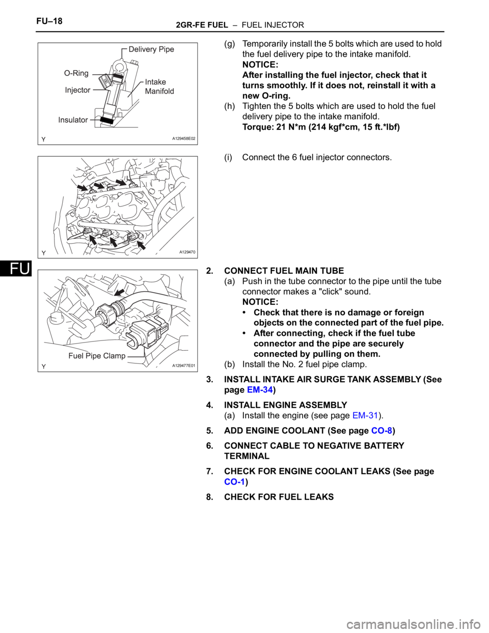
(g) Temporarily install the 5 bolts which are used to hold
the fuel delivery pipe to the intake manifold.
NOTICE:
After installing the fuel injector, check that it
turns smoothly. If it does not, reinstall it with a
new O-ring.
(h) Tighten the 5 bolts which are used to hold the fuel
delivery pipe to the intake manifold.
Torque: 21 N*m (214 kgf*cm, 15 ft.*lbf)
(i) Connect the 6 fuel injector connectors.
2. CONNECT FUEL MAIN TUBE
(a) Push in the tube connector to the pipe until the tube
connector makes a "click" sound.
NOTICE:
• Check that there is no damage or foreign
objects on the connected part of the fuel pipe.
• After connecting, check if the fuel tube
connector and the pipe are securely
connected by pulling on them.
(b) Install the No. 2 fuel pipe clamp.
3. INSTALL INTAKE AIR SURGE TANK ASSEMBLY (See
page EM-34)
4. INSTALL ENGINE ASSEMBLY
(a) Install the engine (see page EM-31).
5. ADD ENGINE COOLANT (See page CO-8)
6. CONNECT CABLE TO NEGATIVE BATTERY
TERMINAL
7. CHECK FOR ENGINE COOLANT LEAKS (See page
CO-1)
8. CHECK FOR FUEL LEAKS
A129458E02
A129470
A129477E01
Page 831 of 2000
EC–222AZ-FE EMISSION CONTROL – AIR FUEL RATIO SENSOR
EC
REMOVAL
1. DISCONNECT CABLE FROM NEGATIVE BATTERY
TERMINAL
CAUTION:
Wait at least 90 seconds after disconnecting the
cable from the negative (-) battery terminal to
prevent airbag and seat belt pretensioner activation.
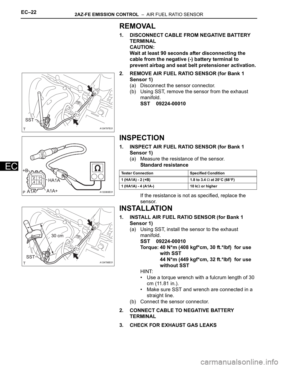
2. REMOVE AIR FUEL RATIO SENSOR (for Bank 1
Sensor 1)
(a) Disconnect the sensor connector.
(b) Using SST, remove the sensor from the exhaust
manifold.
SST 09224-00010
INSPECTION
1. INSPECT AIR FUEL RATIO SENSOR (for Bank 1
Sensor 1)
(a) Measure the resistance of the sensor.
Standard resistance
If the resistance is not as specified, replace the
sensor.
INSTALLATION
1. INSTALL AIR FUEL RATIO SENSOR (for Bank 1
Sensor 1)
(a) Using SST, install the sensor to the exhaust
manifold.
SST 09224-00010
Torque: 40 N*m (408 kgf*cm, 30 ft.*lbf) for use
with SST
44 N*m (449 kgf*cm, 32 ft.*lbf) for use
without SST
HINT:
• Use a torque wrench with a fulcrum length of 30
cm (11.81 in.).
• Make sure SST and wrench are connected in a
straight line.
(b) Connect the sensor connector.
2. CONNECT CABLE TO NEGATIVE BATTERY
TERMINAL
3. CHECK FOR EXHAUST GAS LEAKS
A124797E01
A133069E01
Tester Connection Specified Condition
1 (HA1A) - 2 (+B) 1.8 to 3.4
at 20C (68F)
1 (HA1A) - 4 (A1A-) 10 k
or higher
A124798E01
Page 838 of 2000
EC–242GR-FE EMISSION CONTROL – AIR FUEL RATIO SENSOR
EC
INSTALLATION
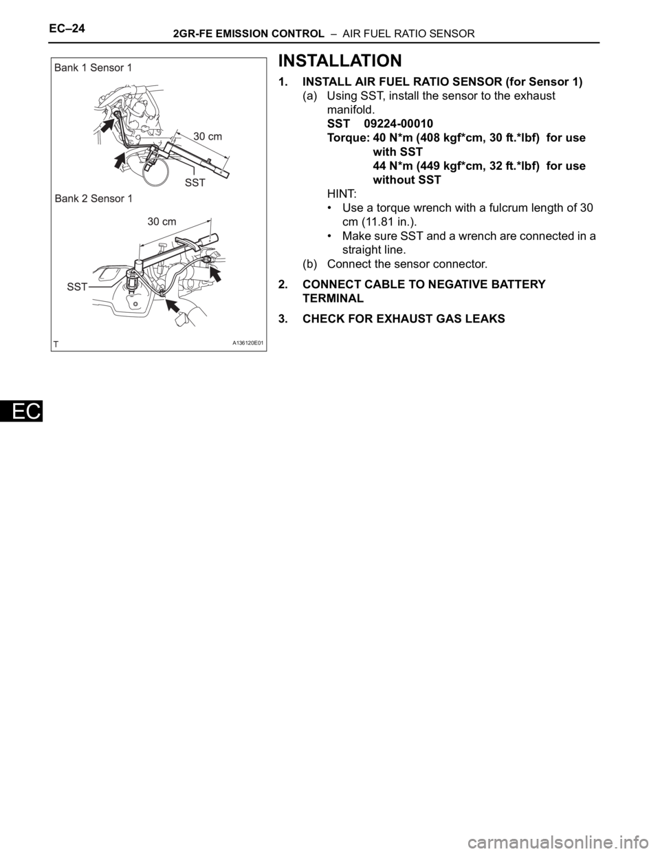
1. INSTALL AIR FUEL RATIO SENSOR (for Sensor 1)
(a) Using SST, install the sensor to the exhaust
manifold.
SST 09224-00010
Torque: 40 N*m (408 kgf*cm, 30 ft.*lbf) for use
with SST
44 N*m (449 kgf*cm, 32 ft.*lbf) for use
without SST
HINT:
• Use a torque wrench with a fulcrum length of 30
cm (11.81 in.).
• Make sure SST and a wrench are connected in a
straight line.
(b) Connect the sensor connector.
2. CONNECT CABLE TO NEGATIVE BATTERY
TERMINAL
3. CHECK FOR EXHAUST GAS LEAKS
A136120E01