display TOYOTA RAV4 2006 Service Repair Manual
[x] Cancel search | Manufacturer: TOYOTA, Model Year: 2006, Model line: RAV4, Model: TOYOTA RAV4 2006Pages: 2000, PDF Size: 45.84 MB
Page 34 of 2000

ENGINE - 2AZ-FE ENGINE
00REG21Y
D13N11
Air-fuel
Ratio
SensorA1A+
(3.3V)
A1A -
(2.9V)ECMHeated
Oxygen
SensorOX1B
EX1BECM
Air-fuel Ratio Sensor Circuit Heated Oxygen Sensor
: Air-fuel Ratio Sensor
: Heated Oxygen Sensor
Air-fuel Ratio Sensor Data
Displayed on Hand-held
Te s t e r4.2
2.2
11 (Rich) 14.7 19 (Lean)0.11
Heated Oxygen
Sensor Output (V)
Air-fuel RatioEG-37
Air-fuel Ratio Sensor and Heated Oxygen Sensor
1) General
The air-fuel ratio sensor and heated oxygen sensor differ in output characteristics.
Approximately 0.4V is constantly applied to the air-fuel ratio sensor, which outputs an amperage that
varies in accordance with the oxygen concentration in the exhaust emission. The ECM converts the
changes in the output amperage into voltage in order to linearly detect the present air-fuel ratio. The
air-fuel ratio sensor data is read out by the hand-held tester.
The output voltage of the heated oxygen sensor changes in accordance with the oxygen concentration
in the exhaust emission. The ECM uses this output voltage to determine whether the present air-fuel
ratio is richer or leaner than the stoichiometric air-fuel ratio.
Page 209 of 2000

IN–26INTRODUCTION – REPAIR INSTRUCTION
IN
CUSTOMIZE PARAMETERS
NOTICE:
• When the customer requests a change in a function,
first make sure that the function can be customized.
• Make a note of the current settings before
customizing.
• When troubleshooting a function, first make sure that
the function is set to the default setting.
1. Combination meter
2. Air conditioning system
3. Power Door Lock Control System
4. Wireless Door Lock Control System
Display (Item) Default Function Setting
SEAT BELT WARN D/P ON Seat belt warning buzzer ON /
OFF settingD/P ON: Driver and passenger
buzzer ON
D ON: Driver buzzer ON
P ON: Passenger buzzer ON
D/P OFF: Driver and passenger
buzzer OFF
Display (Item) Default Contents Setting
SET TEMP SHIFT
(Set Temperature Shift)NORMALTo control with shifted temperature against
display temperature+2 C / +1 C / NORMAL / -1 C / -2
C
AIR INLET MODE
(Air Inlet Mode)AUTOIn case of turning A/C ON when you desire to
make compartment cool down quickly, this is
function to change mode automatically to
RECIRCULATION modeMANUAL / AUTO
COMPRESSOR MODE
(Compressor Mode)AUTOFunction to turn A/C ON automatically by
pressing AUTO button when blower is ON
and A/C is OFFMANUAL / AUTO
COMPRS / DEF OPER
(Compressor / Air Inlet DEF
Operation)LINKFunction to turn A/C ON automatically linked
with FRONT DEF button when A/C is OFFNORMAL / LINK
EVAP CTRL
(Evaporator Control)AUTOFunction to set evaporator control to
AUTOMATIC position (AUTO) to save power,
or to coldest position (MANUAL) to dehumidify
air and to prevent windows from fogging upMANUAL / AUTO
FOOT / DEF MODE
(Foot / DEF auto mode)ONFunction to turn airflow from FOOT / DEF ON
automatically when AUTO MODE is ONOFF / ON
AUTO BLOW UP
(Foot / DEF automatic blower up
function)ONFunction to change blower level automatically
when defroster is ONOFF / ON
Display (Item) Default Function Setting
UNLK/KEY TWICE ON Unlocks only driver side door
when driver side door key
cylinder turned to unlock once,
and unlocks all doors when
turned to unlock twice. For OFF
setting, turning it once unlocks all
doors.ON / OFF
Display (Item) Default Contents Setting
HAZARD ANS BACK ONWhen LOCK switch on
transmitter pressed, all hazard
warning lights illuminate once.
When UNLOCK switch pressed,
all hazard warning lights
illuminate twiceON / OFF
Page 210 of 2000

INTRODUCTION – REPAIR INSTRUCTIONIN–27
IN
5. Lighting System
WIRLS BUZZ OPER ONFunction that makes wireless
buzzer sound for answer-back
when transmitter LOCK /
UNLOCK switch pressedON / OFF
OPEN DOOR WARN ONIf door is not completely closed
and transmitter LOCK switch is
pressed, this function sounds a
buzzer for 10 secondsON / OFF
WIRELESS OPER ONON / OFF of wireless door lock
functionON / OFF
ALARM FUNCTION ONOperates security alarm when
PANIC switch on transmitter
continuously pressed for 1
secondON / OFF
UNLOCK / 2 OPER ONFunction that unlocks driver side
door when unlock switch on
transmitter is pressed once, and
unlocks all doors when pressed
twice. If setting is OFF, pressing
unlock switch once makes all
doors unlock.ON / OFF
AUTO LOCK DELAY 30sThis function controls amount of
time from unlocking doors to
automatic re-locking function30s / 60s Display (Item) Default Contents Setting
Display (Item) Default Contents Setting
LIGHTING TIME
(Lighting Time)15 secondsChanges illumination duration
after door closure.
(It will quickly fade out in case of
turning ignition switch ON.)7.5/15/30 (seconds)
I/L ON /ACC OFF
(Room light illuminates when
ignition switch turned OFF)ONIlluminates light when ignition
switch turned to ACC.
(Room light illuminated when
interior light switch in DOOR
position)ON / OFF
I/L ON / UNLOCK
(Room light illuminates when
door key unlocked.)ONFunction to light up room light
when unlocking with door key
cylinder.
(Room light illuminated when
interior light switch in DOOR
position)ON / OFF
LIGHT CONTROL ONFunction to light up foot light
when ignition switch is ON and
shift position is not P.ON / OFF
Page 436 of 2000

SEAT BELT – SEAT BELT WARNING SYSTEMSB–3
SB
SYSTEM DESCRIPTION
1. DRIVER SEAT BELT WARNING LIGHT
(a) When the driver seat belt is not fastened with the
ignition switch ON, the driver seat belt warning light
on the combination meter comes on to inform the
driver. The center airbag sensor detects the driver
seat belt status and sends signals to the
combination meter through the CAN bus line.
2. PASSENGER SEAT BELT WARNING LIGHT
(a) for Automatic air conditioning system:
When the passenger seat belt is not fastened with
the ignition switch ON and the passenger seat
occupied, check that the passenger seat belt
warning light on the heater control panel display
blinks. The combination meter detects the
passenger seat belt status and whether the
passenger seat is occupied.
(b) for Manual air conditioning system:
When the passenger seat belt is not fastened with
the ignition switch ON and the passenger seat
occupied, check that the passenger seat belt
warning light on the clock panel blinks. The
combination meter detects the passenger seat belt
status and whether the passenger seat is occupied.
Page 463 of 2000

2AZ-FE ENGINE CONTROL SYSTEM – SFI SYSTEMES–9
ES
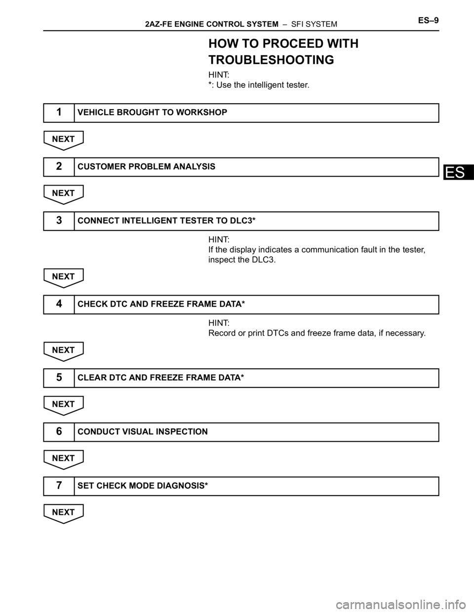
HOW TO PROCEED WITH
TROUBLESHOOTING
HINT:
*: Use the intelligent tester.
NEXT
NEXT
HINT:
If the display indicates a communication fault in the tester,
inspect the DLC3.
NEXT
HINT:
Record or print DTCs and freeze frame data, if necessary.
NEXT
NEXT
NEXT
NEXT
1VEHICLE BROUGHT TO WORKSHOP
2CUSTOMER PROBLEM ANALYSIS
3CONNECT INTELLIGENT TESTER TO DLC3*
4CHECK DTC AND FREEZE FRAME DATA*
5CLEAR DTC AND FREEZE FRAME DATA*
6CONDUCT VISUAL INSPECTION
7SET CHECK MODE DIAGNOSIS*
Page 475 of 2000

2AZ-FE ENGINE CONTROL SYSTEM – SFI SYSTEMES–21
ES
CHECKING MONITOR STATUS
The purpose of the monitor result (mode 06) is to allow
access to the results of on-board diagnostic monitoring tests
of specific components/systems that are not continuously
monitored. Examples are catalysts, evaporative emissions
(EVAP) and thermostats.
The monitor result allows the OBD II scan tool to display the
monitor status, test value, minimum test limit and maximum
test limit. These data are displayed after the vehicle has been
driven to run the monitor.
When the test value is not between the minimum and
maximum test limits, the ECM (PCM) interprets this as a
malfunction. If the test value is on the borderline of the test
limits, the component is likely to malfunction in the near
future.
Perform the following instruction to view the monitor status.
Although this instruction refers to the Lexus/Toyota diagnostic
tester, it can be checked using a generic OBD II scan tool.
Refer to your scan tool operator's manual for specific
procedural information.
1. PERFORM MONITOR DRIVE PATTERN
(a) Connect the intelligent tester to the DLC3.
(b) Turn the ignition switch and the tester ON.
(c) Clear the DTCs (see page ES-35).
(d) Run the vehicle in accordance with the applicable
drive pattern described in READINESS MONITOR
DRIVE PATTERN (see page ES-19). Do not turn the
ignition switch OFF.
NOTE:
The test results will be lost if the ignition
switch is turned OFF.
2. ACCESS MONITOR RESULT
(a) Select the following items from the intelligent tester
menus: DIAGNOSIS, ENHANCED OBD II,
MONITOR INFO and MONITOR RESULT. The
monitor status appears after the component name.
• INCMP: The component has not been monitored
yet.
• PASS: The component is functioning normally.
• FAIL: The component is malfunctioning.
(b) Confirm that the component is either PASS or FAIL.
(c) Select the component and press ENTER. The
accuracy test value appears if the monitor status is
either PASS or FAIL.
3. CHECK COMPONENT STATUS
(a) Compare the test value with the minimum test limit
(MIN LIMIT) and maximum test limit (MAX LIMIT).
Page 479 of 2000

2AZ-FE ENGINE CONTROL SYSTEM – SFI SYSTEMES–25
ES
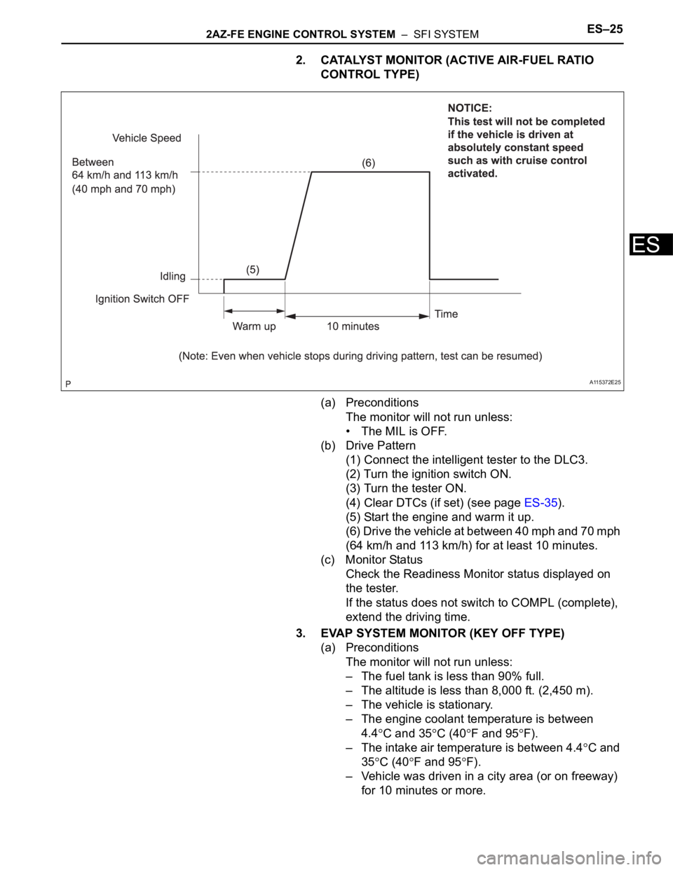
2. CATALYST MONITOR (ACTIVE AIR-FUEL RATIO
CONTROL TYPE)
(a) Preconditions
The monitor will not run unless:
• The MIL is OFF.
(b) Drive Pattern
(1) Connect the intelligent tester to the DLC3.
(2) Turn the ignition switch ON.
(3) Turn the tester ON.
(4) Clear DTCs (if set) (see page ES-35).
(5) Start the engine and warm it up.
(6) Drive the vehicle at between 40 mph and 70 mph
(64 km/h and 113 km/h) for at least 10 minutes.
(c) Monitor Status
Check the Readiness Monitor status displayed on
the tester.
If the status does not switch to COMPL (complete),
extend the driving time.
3. EVAP SYSTEM MONITOR (KEY OFF TYPE)
(a) Preconditions
The monitor will not run unless:
– The fuel tank is less than 90% full.
– The altitude is less than 8,000 ft. (2,450 m).
– The vehicle is stationary.
– The engine coolant temperature is between
4.4
C and 35C (40F and 95F).
– The intake air temperature is between 4.4
C and
35
C (40F and 95F).
– Vehicle was driven in a city area (or on freeway)
for 10 minutes or more.
A115372E25
Page 480 of 2000

ES–262AZ-FE ENGINE CONTROL SYSTEM – SFI SYSTEM
ES
(b) Monitor Conditions
(1) Turn the ignition switch OFF and wait for 6
hours.
HINT:
Do not start the engine until checking Readiness
Monitor status. If the engine is started, the step
described above must be repeated.
(c) Monitor Status
(1) Connect the intelligent tester to the DLC3.
(2) Turn the ignition switch ON.
(3) Turn the tester ON.
(4) Check the Readiness Monitor status displayed
on the tester.
If the status does not switch to COMPL (complete), restart the
engine, make sure that the preconditions have been met, and
then perform the Monitor Conditions again.
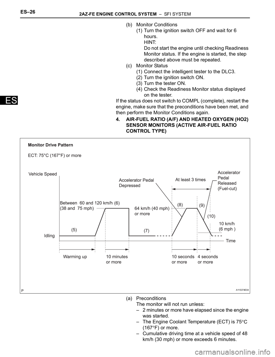
4. AIR-FUEL RATIO (A/F) AND HEATED OXYGEN (HO2)
SENSOR MONITORS (ACTIVE AIR-FUEL RATIO
CONTROL TYPE)
(a) Preconditions
The monitor will not run unless:
– 2 minutes or more have elapsed since the engine
was started.
– The Engine Coolant Temperature (ECT) is 75
C
(167
F) or more.
– Cumulative driving time at a vehicle speed of 48
km/h (30 mph) or more exceeds 6 minutes.
A115374E04
Page 481 of 2000

2AZ-FE ENGINE CONTROL SYSTEM – SFI SYSTEMES–27
ES
– Air-fuel ratio feedback control is performed.
(b) Drive Pattern for front A/F sensor and HO2 sensor
(1) Connect the intelligent tester to the DLC3.
(2) Turn the ignition switch ON.
(3) Turn the tester ON.
(4) Clear DTCs (see page ES-35).
(5) Start the engine, and warm it up until the ECT
reaches 75
C (167F) or higher.
(6) Drive the vehicle at between 60 km/h (38 mph)
and 120 km/h (75 mph) for at least 10 minutes.
(7) Change the transmission to 2nd gear.
(8) Accelerate the vehicle to 64 km/h (40 mph) or
more by depressing the accelerator pedal for at
least 10 seconds.
(9) Soon after performing step (8) above, release
the accelerator pedal for at least 4 seconds without
depressing the brake pedal, in order to execute fuel-
cut control.
(10) Allow the vehicle to decelerate until the vehicle
speed declines to less than 10 km/h (6 mph).
(11) Repeat steps from (8) through (10) above at
least 3 times in one driving cycle.
(c) Monitor Status
(1) Check the Readiness Monitor status displayed
on the tester.
(2) If the status does not switch to COMPL
(complete), make sure that the preconditions
have been met, and then perform steps from (5)
through (11) in the Drive Pattern above.
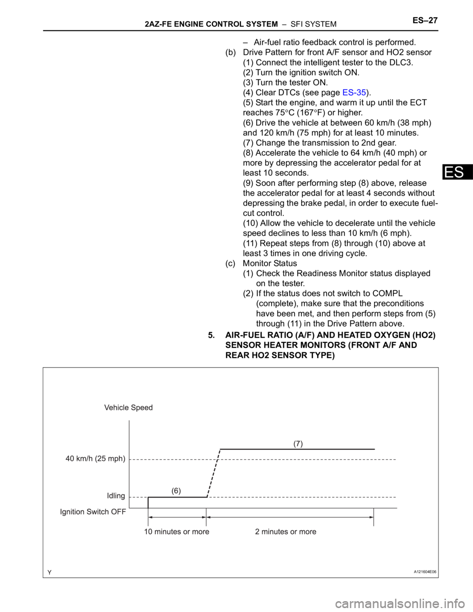
5. AIR-FUEL RATIO (A/F) AND HEATED OXYGEN (HO2)
SENSOR HEATER MONITORS (FRONT A/F AND
REAR HO2 SENSOR TYPE)
A121604E06
Page 482 of 2000

ES–282AZ-FE ENGINE CONTROL SYSTEM – SFI SYSTEM
ES
(a) Preconditions
The monitor will not run unless:
– The MIL is OFF.
(b) Drive Pattern
(1) Connect the intelligent tester to the DLC3.
(2) Turn the ignition switch ON.
(3) Turn the tester ON.
(4) Clear DTCs (if set) (see page ES-35).
(5) Start the engine.
(6) Allow the engine to idle for 10 minutes or more.
(7) Drive the vehicle at 40 km/h (25 mph) or more
for at least 2 minutes.
(c) Monitor Status
(1) Check the Readiness Monitor status displayed
on the tester.
If the status does not switch to COMPL
(complete), make sure that the preconditions
have been met, and repeat steps from (5) to (7)
described in the Drive Pattern above.