Rele TOYOTA RAV4 2006 Service Repair Manual
[x] Cancel search | Manufacturer: TOYOTA, Model Year: 2006, Model line: RAV4, Model: TOYOTA RAV4 2006Pages: 2000, PDF Size: 45.84 MB
Page 51 of 2000

ENGINE - 2AZ-FE ENGINE
Service Tip
The canister pump module performs the EVAP leak check. This check is done approximately five
hours after the engine is turned off. So you may hear sound coming from underneath the luggage
compartment for several minutes. It does not indicate a malfunction.
The pinpoint pressure test procedure is carried out by pressurizing the fresh air line that runs from
the pump module to the air filler neck. For details, refer to the 2006 RAV4 Repair Manual (Pub.
No. RM01M1U).
EG-54
10. EVAP (evaporative Emission) Control System
General
The EVAP (evaporative emission) control system prevents the vapor gas that is created in the fuel tank from
being released directly into the atmosphere.
The canister stores the vapor gas that has been created in the fuel tank.
The ECM controls the purge VSV in accordance with the driving conditions in order to direct the vapor
gas into the engine, where it is burned.
In this system, the ECM checks the evaporative emission leak and outputs DTC (Diagnostic Trouble
Code) in the event of a malfunction. An EVAP (evaporative emission) leak check consists of an
application of a vacuum pressure to the system and monitoring the changes in the system pressure in order
to detect a leakage.
This system consists of the purge VSV, canister, refueling valve, canister pump module, and ECM.
The ORVR (Onboard Refueling Vapor Recovery) function is provided in the refueling valve.
The canister pressure sensor has been included to the canister pump module.
The canister filter has been provided on the fresh air line. This canister filter is maintenance-free.
The followings are the typical conditions for enabling an EVAP leak check:
Typical Enabling
Condition
Five hours have elapsed after the engine has been turned OFF*.
Altitude: Below 2400 m (8000 feet)
Battery voltage: 10.5 V or more
Ignition switch: OFF
Engine coolant temperature: 4.4 to 35C (40 to 95F)
Intake air temperature: 4.4 to 35C (40 to 95F)
*: If engine coolant temperature does not drop below 35C (95F), this time should be extended to 7hours.
Even after that, if the temperature is not less than 35
C (95F), the time should be extended to 9.5 hours.
Page 167 of 2000
IN–22INTRODUCTION – REPAIR INSTRUCTION
IN
VEHICLE LIFT AND SUPPORT
LOCATIONS
1. NOTICE ABOUT VEHICLE CONDITION WHEN
JACKING UP VEHICLE
(a) The vehicle must be unloaded before jacking up /
lifting up the vehicle. Never jack up / lift up a heavily
loaded vehicle.
(b) When removing heavy parts such as the engine and
transmission, the center of gravity of the vehicle
may shift. To stabilize the vehicle, place a balance
weight in a location where it will not roll or shift, or
use a mission jack to hold the jacking support.
2. NOTICE FOR USING 4 POST LIFT
(a) Follow the safety procedures outlined in the lift
instruction manual.
(b) Use precautionary measures to prevent the free
wheel beam from damaging tires or wheels.
(c) Use wheel chocks to secure the vehicle.
3. NOTICE FOR USING JACK AND SAFETY STAND
(a) Work on a level surface. Use wheel chocks at all
times.
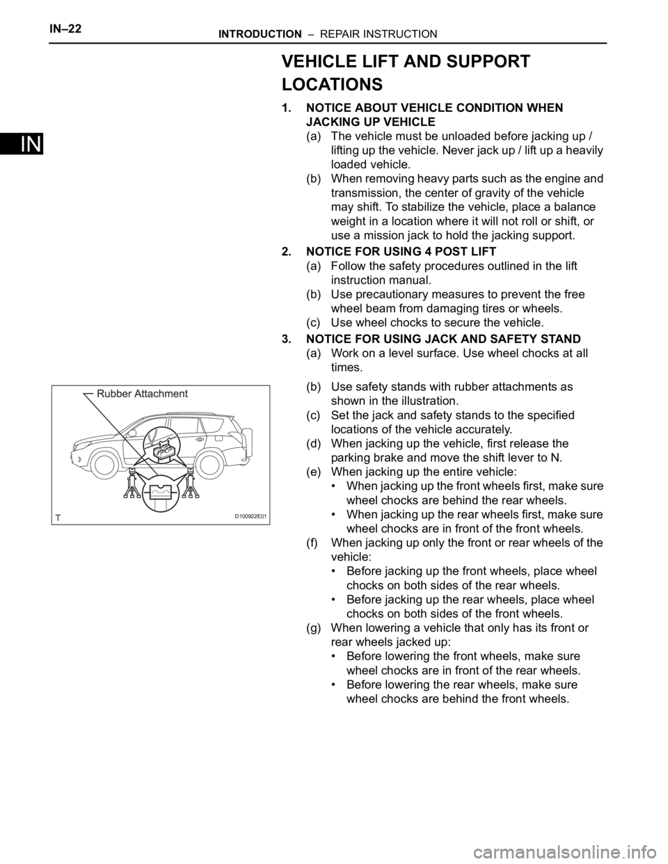
(b) Use safety stands with rubber attachments as
shown in the illustration.
(c) Set the jack and safety stands to the specified
locations of the vehicle accurately.
(d) When jacking up the vehicle, first release the
parking brake and move the shift lever to N.
(e) When jacking up the entire vehicle:
• When jacking up the front wheels first, make sure
wheel chocks are behind the rear wheels.
• When jacking up the rear wheels first, make sure
wheel chocks are in front of the front wheels.
(f) When jacking up only the front or rear wheels of the
vehicle:
• Before jacking up the front wheels, place wheel
chocks on both sides of the rear wheels.
• Before jacking up the rear wheels, place wheel
chocks on both sides of the front wheels.
(g) When lowering a vehicle that only has its front or
rear wheels jacked up:
• Before lowering the front wheels, make sure
wheel chocks are in front of the rear wheels.
• Before lowering the rear wheels, make sure
wheel chocks are behind the front wheels.
D100922E01
Page 209 of 2000

IN–26INTRODUCTION – REPAIR INSTRUCTION
IN
CUSTOMIZE PARAMETERS
NOTICE:
• When the customer requests a change in a function,
first make sure that the function can be customized.
• Make a note of the current settings before
customizing.
• When troubleshooting a function, first make sure that
the function is set to the default setting.
1. Combination meter
2. Air conditioning system
3. Power Door Lock Control System
4. Wireless Door Lock Control System
Display (Item) Default Function Setting
SEAT BELT WARN D/P ON Seat belt warning buzzer ON /
OFF settingD/P ON: Driver and passenger
buzzer ON
D ON: Driver buzzer ON
P ON: Passenger buzzer ON
D/P OFF: Driver and passenger
buzzer OFF
Display (Item) Default Contents Setting
SET TEMP SHIFT
(Set Temperature Shift)NORMALTo control with shifted temperature against
display temperature+2 C / +1 C / NORMAL / -1 C / -2
C
AIR INLET MODE
(Air Inlet Mode)AUTOIn case of turning A/C ON when you desire to
make compartment cool down quickly, this is
function to change mode automatically to
RECIRCULATION modeMANUAL / AUTO
COMPRESSOR MODE
(Compressor Mode)AUTOFunction to turn A/C ON automatically by
pressing AUTO button when blower is ON
and A/C is OFFMANUAL / AUTO
COMPRS / DEF OPER
(Compressor / Air Inlet DEF
Operation)LINKFunction to turn A/C ON automatically linked
with FRONT DEF button when A/C is OFFNORMAL / LINK
EVAP CTRL
(Evaporator Control)AUTOFunction to set evaporator control to
AUTOMATIC position (AUTO) to save power,
or to coldest position (MANUAL) to dehumidify
air and to prevent windows from fogging upMANUAL / AUTO
FOOT / DEF MODE
(Foot / DEF auto mode)ONFunction to turn airflow from FOOT / DEF ON
automatically when AUTO MODE is ONOFF / ON
AUTO BLOW UP
(Foot / DEF automatic blower up
function)ONFunction to change blower level automatically
when defroster is ONOFF / ON
Display (Item) Default Function Setting
UNLK/KEY TWICE ON Unlocks only driver side door
when driver side door key
cylinder turned to unlock once,
and unlocks all doors when
turned to unlock twice. For OFF
setting, turning it once unlocks all
doors.ON / OFF
Display (Item) Default Contents Setting
HAZARD ANS BACK ONWhen LOCK switch on
transmitter pressed, all hazard
warning lights illuminate once.
When UNLOCK switch pressed,
all hazard warning lights
illuminate twiceON / OFF
Page 210 of 2000

INTRODUCTION – REPAIR INSTRUCTIONIN–27
IN
5. Lighting System
WIRLS BUZZ OPER ONFunction that makes wireless
buzzer sound for answer-back
when transmitter LOCK /
UNLOCK switch pressedON / OFF
OPEN DOOR WARN ONIf door is not completely closed
and transmitter LOCK switch is
pressed, this function sounds a
buzzer for 10 secondsON / OFF
WIRELESS OPER ONON / OFF of wireless door lock
functionON / OFF
ALARM FUNCTION ONOperates security alarm when
PANIC switch on transmitter
continuously pressed for 1
secondON / OFF
UNLOCK / 2 OPER ONFunction that unlocks driver side
door when unlock switch on
transmitter is pressed once, and
unlocks all doors when pressed
twice. If setting is OFF, pressing
unlock switch once makes all
doors unlock.ON / OFF
AUTO LOCK DELAY 30sThis function controls amount of
time from unlocking doors to
automatic re-locking function30s / 60s Display (Item) Default Contents Setting
Display (Item) Default Contents Setting
LIGHTING TIME
(Lighting Time)15 secondsChanges illumination duration
after door closure.
(It will quickly fade out in case of
turning ignition switch ON.)7.5/15/30 (seconds)
I/L ON /ACC OFF
(Room light illuminates when
ignition switch turned OFF)ONIlluminates light when ignition
switch turned to ACC.
(Room light illuminated when
interior light switch in DOOR
position)ON / OFF
I/L ON / UNLOCK
(Room light illuminates when
door key unlocked.)ONFunction to light up room light
when unlocking with door key
cylinder.
(Room light illuminated when
interior light switch in DOOR
position)ON / OFF
LIGHT CONTROL ONFunction to light up foot light
when ignition switch is ON and
shift position is not P.ON / OFF
Page 215 of 2000
IN–38INTRODUCTION – HOW TO TROUBLESHOOT ECU CONTROLLED SYSTEMS
IN
ELECTRONIC CIRCUIT INSPECTION
PROCEDURE
1. BASIC INSPECTION
(a) WHEN MEASURING RESISTANCE OF
ELECTRONIC PARTS
(1) Unless otherwise stated, all resistance
measurements should be made at an ambient
temperature of 20
C (68F). Resistance
measurements may be inaccurate if measured
at high temperatures, i.e. immediately after the
vehicle has been running. Measurements should
be made after the engine has cooled down.
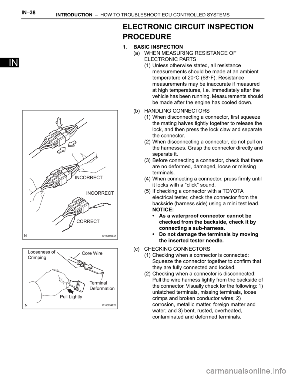
(b) HANDLING CONNECTORS
(1) When disconnecting a connector, first squeeze
the mating halves tightly together to release the
lock, and then press the lock claw and separate
the connector.
(2) When disconnecting a connector, do not pull on
the harnesses. Grasp the connector directly and
separate it.
(3) Before connecting a connector, check that there
are no deformed, damaged, loose or missing
terminals.
(4) When connecting a connector, press firmly until
it locks with a "click" sound.
(5) If checking a connector with a TOYOTA
electrical tester, check the connector from the
backside (harness side) using a mini test lead.
NOTICE:
• As a waterproof connector cannot be
checked from the backside, check it by
connecting a sub-harness.
• Do not damage the terminals by moving
the inserted tester needle.
(c) CHECKING CONNECTORS
(1) Checking when a connector is connected:
Squeeze the connector together to confirm that
they are fully connected and locked.
(2) Checking when a connector is disconnected:
Pull the wire harness lightly from the backside of
the connector. Visually check for the following: 1)
unlatched terminals, missing terminals, loose
crimps and broken conductor wires; 2)
corrosion, metallic matter, foreign matter and
water; and 3) bent, rusted, overheated,
contaminated and deformed terminals.
D100803E01
D100734E01
Page 227 of 2000
2AZ-FE EMISSION CONTROL – EMISSION CONTROL SYSTEMEC–7
EC
ON-VEHICLE INSPECTION
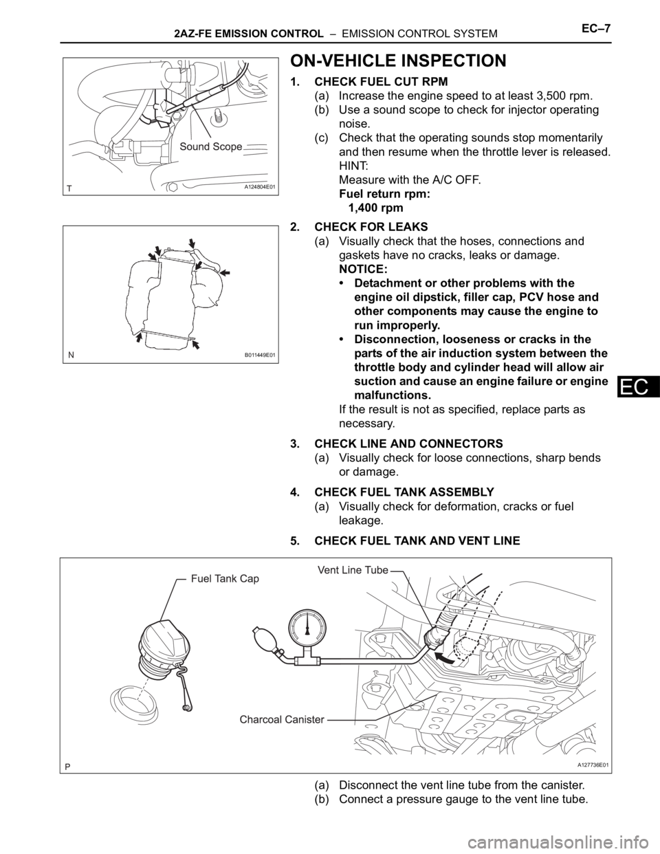
1. CHECK FUEL CUT RPM
(a) Increase the engine speed to at least 3,500 rpm.
(b) Use a sound scope to check for injector operating
noise.
(c) Check that the operating sounds stop momentarily
and then resume when the throttle lever is released.
HINT:
Measure with the A/C OFF.
Fuel return rpm:
1,400 rpm
2. CHECK FOR LEAKS
(a) Visually check that the hoses, connections and
gaskets have no cracks, leaks or damage.
NOTICE:
• Detachment or other problems with the
engine oil dipstick, filler cap, PCV hose and
other components may cause the engine to
run improperly.
• Disconnection, looseness or cracks in the
parts of the air induction system between the
throttle body and cylinder head will allow air
suction and cause an engine failure or engine
malfunctions.
If the result is not as specified, replace parts as
necessary.
3. CHECK LINE AND CONNECTORS
(a) Visually check for loose connections, sharp bends
or damage.
4. CHECK FUEL TANK ASSEMBLY
(a) Visually check for deformation, cracks or fuel
leakage.
5. CHECK FUEL TANK AND VENT LINE
(a) Disconnect the vent line tube from the canister.
(b) Connect a pressure gauge to the vent line tube.
A124804E01
B011449E01
A127736E01
Page 228 of 2000

EC–82AZ-FE EMISSION CONTROL – EMISSION CONTROL SYSTEM
EC
(c) Apply 4 kPa (41 kgf/cm2, 30 mmHg) of pressure to
the vent line of the fuel tank.
HINT:
Perform this inspection with the fuel tank less than
90% full. When the fuel tank is full, the fuel cutoff
valve closes and pressure is released through the
1.5 mm orifice. As a result, when the fuel tank cap is
removed, the pressure does not decrease smoothly.
(d) Check that the fuel tank pressure is maintained for
some time, and does not decrease immediately.
HINT:
If the pressure decreases immediately, one of the
following may be the cause:
• The fuel tank cap is not completely tightened.
• The fuel tank cap is damaged.
• Air is leaking from the vent line.
• The fuel tank is damaged.
(e) When the fuel tank cap is removed, check that
pressure is released smoothly.
HINT:
If the pressure does not drop, replace the fuel tank
assembly.
(f) Reconnect the vent line tube to the canister.
6. CHECK AIR INLET LINE
(a) Disconnect the air inlet line hose from the charcoal
canister.
(b) Check that air flows freely into the air inlet line.
HINT:
If air does not flow freely into the air inlet line, repair
or replace it.
(c) Reconnect the air inlet line hose to the charcoal
canister.
Page 349 of 2000
AX–138U140F AUTOMATIC TRANSAXLE – FLOOR SHIFT ASSEMBLY
AX
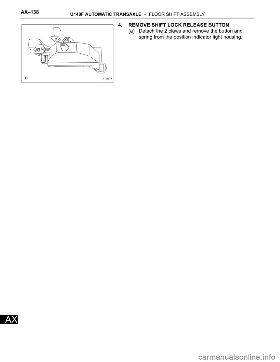
4. REMOVE SHIFT LOCK RELEASE BUTTON
(a) Detach the 2 claws and remove the button and
spring from the position indicator light housing.
C127817
Page 357 of 2000
AX–164U151E AUTOMATIC TRANSAXLE – FLOOR SHIFT ASSEMBLY
AX
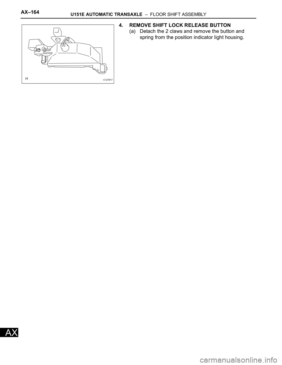
4. REMOVE SHIFT LOCK RELEASE BUTTON
(a) Detach the 2 claws and remove the button and
spring from the position indicator light housing.
C127817
Page 363 of 2000
AX–164U151F AUTOMATIC TRANSAXLE – FLOOR SHIFT ASSEMBLY
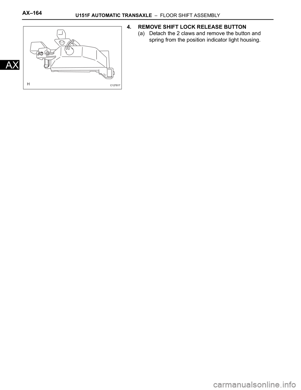
AX
4. REMOVE SHIFT LOCK RELEASE BUTTON
(a) Detach the 2 claws and remove the button and
spring from the position indicator light housing.
C127817