differential TOYOTA RAV4 2006 Service Owners Manual
[x] Cancel search | Manufacturer: TOYOTA, Model Year: 2006, Model line: RAV4, Model: TOYOTA RAV4 2006Pages: 2000, PDF Size: 45.84 MB
Page 1447 of 2000
DIFFERENTIAL – REAR DIFFERENTIAL CARRIER ASSEMBLYDF–43
DF
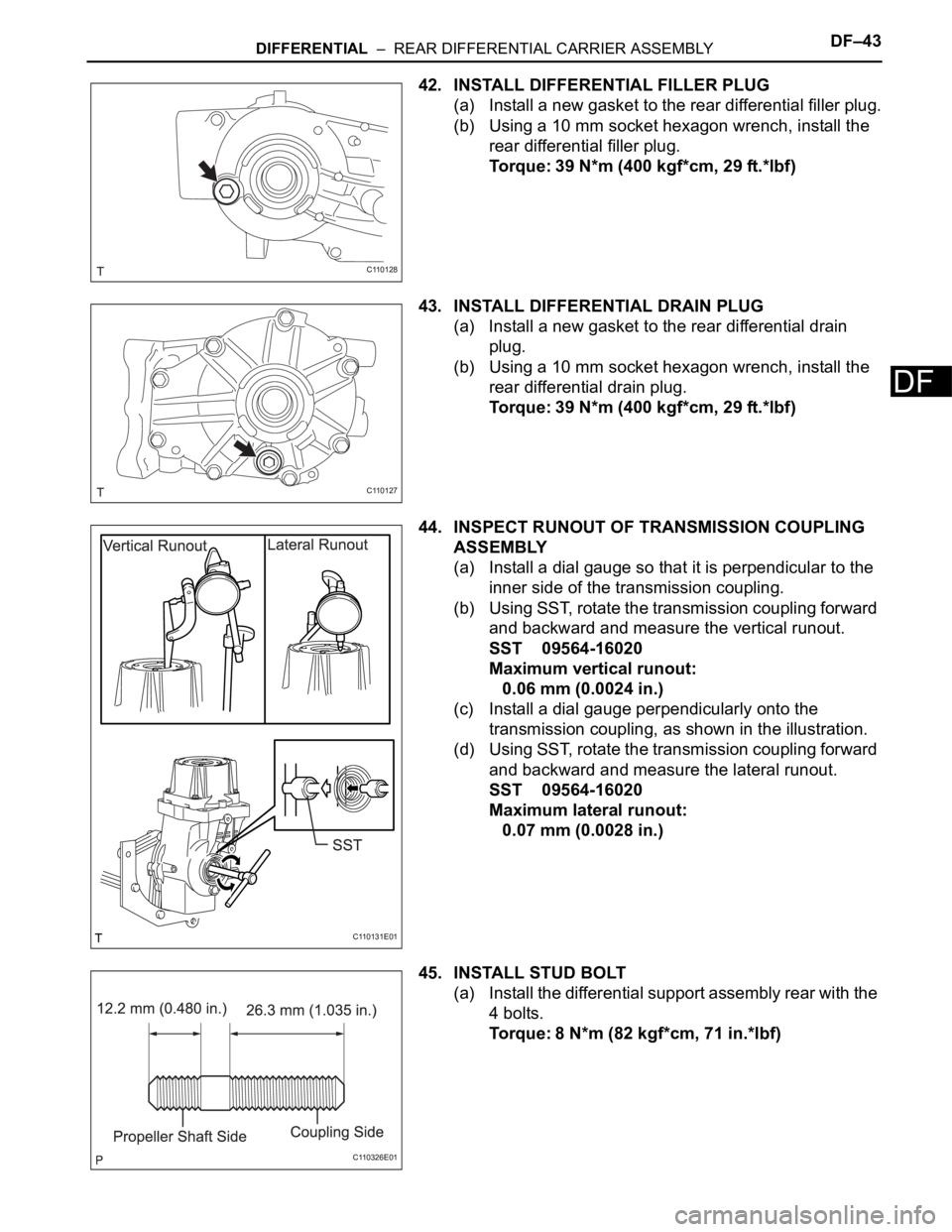
42. INSTALL DIFFERENTIAL FILLER PLUG
(a) Install a new gasket to the rear differential filler plug.
(b) Using a 10 mm socket hexagon wrench, install the
rear differential filler plug.
Torque: 39 N*m (400 kgf*cm, 29 ft.*lbf)
43. INSTALL DIFFERENTIAL DRAIN PLUG
(a) Install a new gasket to the rear differential drain
plug.
(b) Using a 10 mm socket hexagon wrench, install the
rear differential drain plug.
Torque: 39 N*m (400 kgf*cm, 29 ft.*lbf)
44. INSPECT RUNOUT OF TRANSMISSION COUPLING
ASSEMBLY
(a) Install a dial gauge so that it is perpendicular to the
inner side of the transmission coupling.
(b) Using SST, rotate the transmission coupling forward
and backward and measure the vertical runout.
SST 09564-16020
Maximum vertical runout:
0.06 mm (0.0024 in.)
(c) Install a dial gauge perpendicularly onto the
transmission coupling, as shown in the illustration.
(d) Using SST, rotate the transmission coupling forward
and backward and measure the lateral runout.
SST 09564-16020
Maximum lateral runout:
0.07 mm (0.0028 in.)
45. INSTALL STUD BOLT
(a) Install the differential support assembly rear with the
4 bolts.
Torque: 8 N*m (82 kgf*cm, 71 in.*lbf)
C110128
C110127
C110131E01
C110326E01
Page 1448 of 2000
DF–44DIFFERENTIAL – REAR DIFFERENTIAL CARRIER ASSEMBLY
DF
INSTALLATION
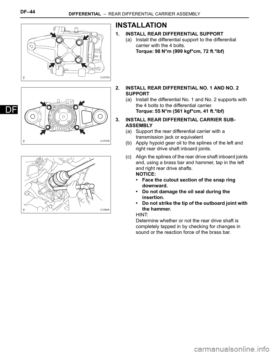
1. INSTALL REAR DIFFERENTIAL SUPPORT
(a) Install the differential support to the differential
carrier with the 4 bolts.
Torque: 98 N*m (999 kgf*cm, 72 ft.*lbf)
2. INSTALL REAR DIFFERENTIAL NO. 1 AND NO. 2
SUPPORT
(a) Install the differential No. 1 and No. 2 supports with
the 4 bolts to the differential carrier.
Torque: 55 N*m (561 kgf*cm, 41 ft.*lbf)
3. INSTALL REAR DIFFERENTIAL CARRIER SUB-
ASSEMBLY
(a) Support the rear differential carrier with a
transmission jack or equivalent
(b) Apply hypoid gear oil to the splines of the left and
right rear drive shaft inboard joints.
(c) Align the splines of the rear drive shaft inboard joints
and, using a brass bar and hammer, tap in the left
and right rear drive shafts.
NOTICE:
• Face the cutout section of the snap ring
downward.
• Do not damage the oil seal during the
insertion.
• Do not strike the tip of the outboard joint with
the hammer.
HINT:
Determine whether or not the rear drive shaft is
completely tapped in by checking for changes in
sound or the reaction force of the brass bar.
C127579
C127578
C129504
Page 1449 of 2000
DIFFERENTIAL – REAR DIFFERENTIAL CARRIER ASSEMBLYDF–45
DF
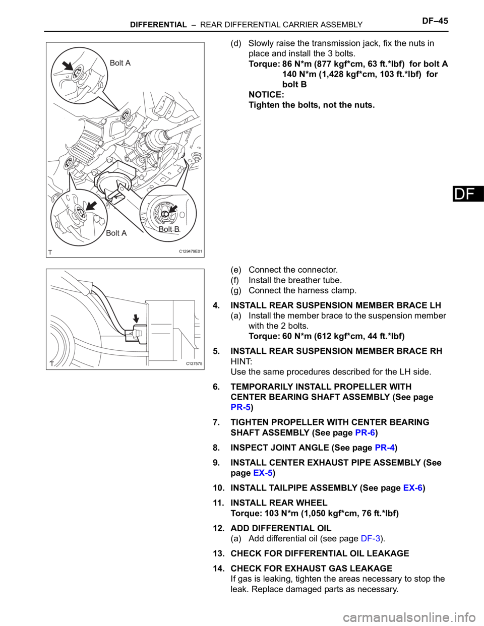
(d) Slowly raise the transmission jack, fix the nuts in
place and install the 3 bolts.
Torque: 86 N*m (877 kgf*cm, 63 ft.*lbf) for bolt A
140 N*m (1,428 kgf*cm, 103 ft.*lbf) for
bolt B
NOTICE:
Tighten the bolts, not the nuts.
(e) Connect the connector.
(f) Install the breather tube.
(g) Connect the harness clamp.
4. INSTALL REAR SUSPENSION MEMBER BRACE LH
(a) Install the member brace to the suspension member
with the 2 bolts.
Torque: 60 N*m (612 kgf*cm, 44 ft.*lbf)
5. INSTALL REAR SUSPENSION MEMBER BRACE RH
HINT:
Use the same procedures described for the LH side.
6. TEMPORARILY INSTALL PROPELLER WITH
CENTER BEARING SHAFT ASSEMBLY (See page
PR-5)
7. TIGHTEN PROPELLER WITH CENTER BEARING
SHAFT ASSEMBLY (See page PR-6)
8. INSPECT JOINT ANGLE (See page PR-4)
9. INSTALL CENTER EXHAUST PIPE ASSEMBLY (See
page EX-5)
10. INSTALL TAILPIPE ASSEMBLY (See page EX-6)
11 . I N S TA L L R E A R WH E E L
Torque: 103 N*m (1,050 kgf*cm, 76 ft.*lbf)
12. ADD DIFFERENTIAL OIL
(a) Add differential oil (see page DF-3).
13. CHECK FOR DIFFERENTIAL OIL LEAKAGE
14. CHECK FOR EXHAUST GAS LEAKAGE
If gas is leaking, tighten the areas necessary to stop the
leak. Replace damaged parts as necessary.
C129479E01
C127575
Page 1518 of 2000
BRAKE CONTROL – VEHICLE STABILITY CONTROL SYSTEMBC–15
BC
(1) Operation description:
When the system is in operation, the following
occurs: 1) the slip indicator light blinks; 2) the
VSC light comes on; and 3) when hill-start assist
control operation starts, the skid control buzzer
sounds once; when hill-start assist control
operation ends, the skid control buzzer sounds
twice.
The VSC warning light comes on when the hill-
start assist control is malfunctioning.
(h) AUTO LSD (Auto Limited Slip Differential) for 2WD:
The AUTO LSD achieves the equivalent functions of
an LSD (Limited Slip Differential) through the use of
a traction control system. When the driver presses
the AUTO LSD switch, this system achieves the
LSD effect by regulating the hydraulic pressure that
acts on the drive wheels and controlling the engine
output in accordance with the amount of pedal effort
applied on the accelerator. The AUTO LSD
operates with the AUTO LSD switch on and the
accelerator pedal depressed.
Auto LSD restrains brake pressure and reduces
differential movement, thus transmitting the drive
torque to the other drive wheel to ensure stability
under the following conditions:
• Wheels run off the road.
• Drive wheels spin in place when starting on a
slope with one wheel on snow/ice.
HINT:
Releasing the accelerator pedal cancels control of
the AUTO LSD system.