differential TOYOTA RAV4 2006 Service Owner's Guide
[x] Cancel search | Manufacturer: TOYOTA, Model Year: 2006, Model line: RAV4, Model: TOYOTA RAV4 2006Pages: 2000, PDF Size: 45.84 MB
Page 999 of 2000
U140F AUTOMATIC TRANSAXLE – AUTOMATIC TRANSAXLE UNITAX–205
AX
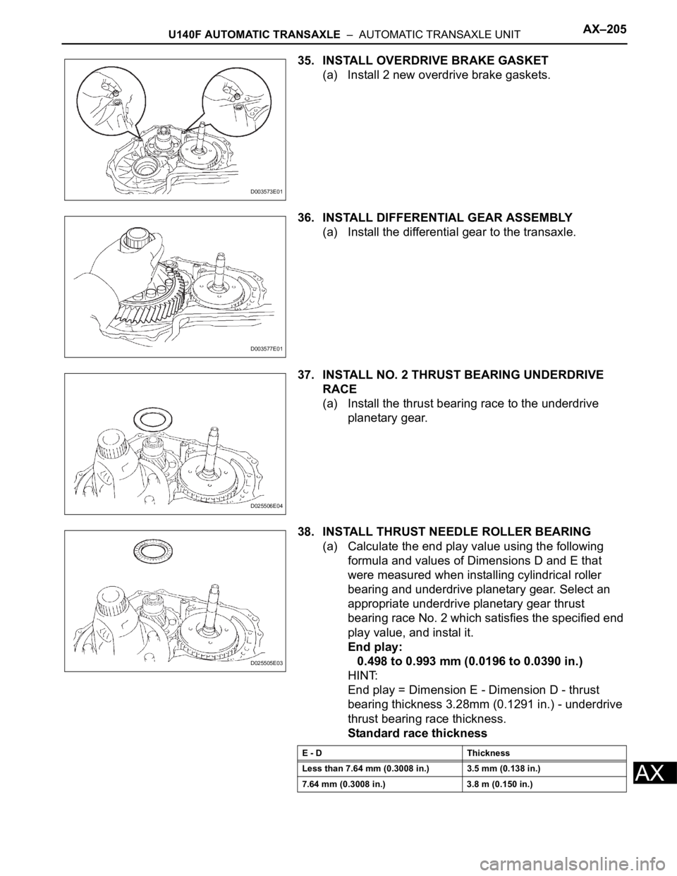
35. INSTALL OVERDRIVE BRAKE GASKET
(a) Install 2 new overdrive brake gaskets.
36. INSTALL DIFFERENTIAL GEAR ASSEMBLY
(a) Install the differential gear to the transaxle.
37. INSTALL NO. 2 THRUST BEARING UNDERDRIVE
RACE
(a) Install the thrust bearing race to the underdrive
planetary gear.
38. INSTALL THRUST NEEDLE ROLLER BEARING
(a) Calculate the end play value using the following
formula and values of Dimensions D and E that
were measured when installing cylindrical roller
bearing and underdrive planetary gear. Select an
appropriate underdrive planetary gear thrust
bearing race No. 2 which satisfies the specified end
play value, and instal it.
End play:
0.498 to 0.993 mm (0.0196 to 0.0390 in.)
HINT:
End play = Dimension E - Dimension D - thrust
bearing thickness 3.28mm (0.1291 in.) - underdrive
thrust bearing race thickness.
Standard race thickness
D003573E01
D003577E01
D025506E04
D025505E03
E - D Thickness
Less than 7.64 mm (0.3008 in.) 3.5 mm (0.138 in.)
7.64 mm (0.3008 in.) 3.8 m (0.150 in.)
Page 1017 of 2000
U140F AUTOMATIC TRANSAXLE – DIFFERENTIAL CASEAX–257
AX
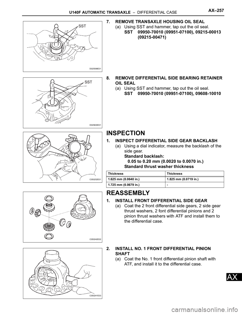
7. REMOVE TRANSAXLE HOUSING OIL SEAL
(a) Using SST and hammer, tap out the oil seal.
SST 09950-70010 (09951-07100), 09215-00013
(09215-00471)
8. REMOVE DIFFERENTIAL SIDE BEARING RETAINER
OIL SEAL
(a) Using SST and hammer, tap out the oil seal.
SST 09950-70010 (09951-07100), 09608-10010
INSPECTION
1. INSPECT DIFFERENTIAL SIDE GEAR BACKLASH
(a) Using a dial indicator, measure the backlash of the
side gear.
Standard backlash:
0.05 to 0.20 mm (0.0020 to 0.0070 in.)
Standard thrust washer thickness
REASSEMBLY
1. INSTALL FRONT DIFFERENTIAL SIDE GEAR
(a) Coat the 2 front differential side gears, 2 side gear
thrust washers, 2 font differential pinions and 2
pinion thrust washers with ATF and install them to
the differential case.
2. INSTALL NO. 1 FRONT DIFFERENTIAL PINION
SHAFT
(a) Coat the No. 1 front differential pinion shaft with
ATF, and install it to the differential case.
D025599E01
D025600E01
C050252E01
Thickness Thickness
1.625 mm (0.0640 in.) 1.825 mm (0.0719 in.)
1.725 mm (0.0679 in.) -
C050242E02
C050241E03
Page 1018 of 2000
AX–258U140F AUTOMATIC TRANSAXLE – DIFFERENTIAL CASE
AX
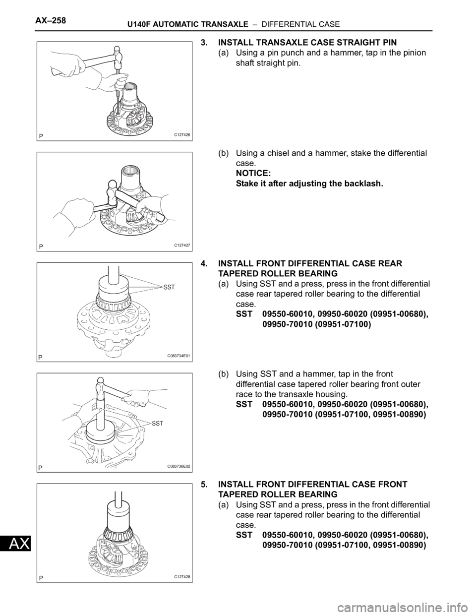
3. INSTALL TRANSAXLE CASE STRAIGHT PIN
(a) Using a pin punch and a hammer, tap in the pinion
shaft straight pin.
(b) Using a chisel and a hammer, stake the differential
case.
NOTICE:
Stake it after adjusting the backlash.
4. INSTALL FRONT DIFFERENTIAL CASE REAR
TAPERED ROLLER BEARING
(a) U si ng SST and a pres s, pr es s in the f ron t di fferent ial
case rear tapered roller bearing to the differential
case.
SST 09550-60010, 09950-60020 (09951-00680),
09950-70010 (09951-07100)
(b) Using SST and a hammer, tap in the front
differential case tapered roller bearing front outer
race to the transaxle housing.
SST 09550-60010, 09950-60020 (09951-00680),
09950-70010 (09951-07100, 09951-00890)
5. INSTALL FRONT DIFFERENTIAL CASE FRONT
TAPERED ROLLER BEARING
(a) Using SST and a press, press in the front differential
case rear tapered roller bearing to the differential
case.
SST 09550-60010, 09950-60020 (09951-00680),
09950-70010 (09951-07100, 09951-00890)
C127426
C127427
C083734E01
C083736E02
C127428
Page 1019 of 2000
U140F AUTOMATIC TRANSAXLE – DIFFERENTIAL CASEAX–259
AX
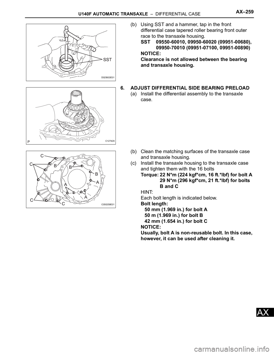
(b) Using SST and a hammer, tap in the front
differential case tapered roller bearing front outer
race to the transaxle housing.
SST 09550-60010, 09950-60020 (09951-00680),
09950-70010 (09951-07100, 09951-00890)
NOTICE:
Clearance is not allowed between the bearing
and transaxle housing.
6. ADJUST DIFFERENTIAL SIDE BEARING PRELOAD
(a) Install the differential assembly to the transaxle
case.
(b) Clean the matching surfaces of the transaxle case
and transaxle housing.
(c) Install the transaxle housing to the transaxle case
and tighten them with the 16 bolts
Torque: 22 N*m (224 kgf*cm, 16 ft.*lbf) for bolt A
29 N*m (296 kgf*cm, 21 ft.*lbf) for bolts
B and C
HINT:
Each bolt length is indicated below.
Bolt length:
50 mm (1.969 in.) for bolt A
50 m (1.969 in.) for bolt B
42 mm (1.654 in.) for bolt C
NOTICE:
Usually, bolt A is non-reusable bolt. In this case,
however, it can be used after cleaning it.
D025603E01
C127429
C050259E01
Page 1020 of 2000
AX–260U140F AUTOMATIC TRANSAXLE – DIFFERENTIAL CASE
AX
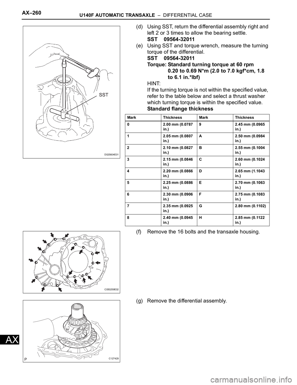
(d) Using SST, return the differential assembly right and
left 2 or 3 times to allow the bearing settle.
SST 09564-32011
(e) Using SST and torque wrench, measure the turning
torque of the differential.
SST 09564-32011
Torque: Standard turning torque at 60 rpm
0.20 to 0.69 N*m (2.0 to 7.0 kgf*cm, 1.8
to 6.1 in.*lbf)
HINT:
If the turning torque is not within the specified value,
refer to the table below and select a thrust washer
which turning torque is within the specified value.
Standard flange thickness
(f) Remove the 16 bolts and the transaxle housing.
(g) Remove the differential assembly.
D025604E01
Mark Thickness Mark Thickness
0 2.00 mm (0.0787
in.)9 2.45 mm (0.0965
in.)
1 2.05 mm (0.0807
in.)A 2.50 mm (0.0984
in.)
2 2.10 mm (0.0827
in.)B 2.55 mm (0.1004
in.)
3 2.15 mm (0.0846
in.)C 2.60 mm (0.1024
in.)
4 2.20 mm (0.0866
in.)D 2.65 mm (1.1043
in.)
5 2.25 mm (0.0886
in.)E 2.70 mm (0.1063
in.)
6 2.30 mm (0.0906
in.)F 2.75 mm (0.1083
in.)
7 2.35 mm (0.0925
in.)G 2.80 mm (0.1102)
8 2.40 mm (0.0945
in.)H 2.85 mm (0.1122
in.)
C050259E02
C127429
Page 1021 of 2000
U140F AUTOMATIC TRANSAXLE – DIFFERENTIAL CASEAX–261
AX
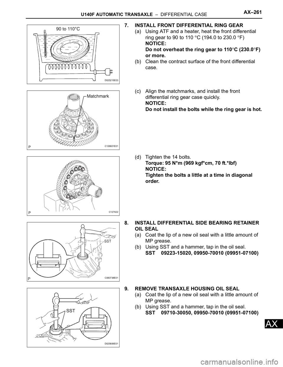
7. INSTALL FRONT DIFFERENTIAL RING GEAR
(a) Using ATF and a heater, heat the front differential
ring gear to 90 to 110
C (194.0 to 230.0 F)
NOTICE:
Do not overheat the ring gear to 110
C (230.0F)
or more.
(b) Clean the contract surface of the front differential
case.
(c) Align the matchmarks, and install the front
differential ring gear case quickly.
NOTICE:
Do not install the bolts while the ring gear is hot.
(d) Tighten the 14 bolts.
Torque: 95 N*m (969 kgf*cm, 70 ft.*lbf)
NOTICE:
Tighten the bolts a little at a time in diagonal
order.
8. INSTALL DIFFERENTIAL SIDE BEARING RETAINER
OIL SEAL
(a) Coat the lip of a new oil seal with a little amount of
MP grease.
(b) Using SST and a hammer, tap in the oil seal.
SST 09223-15020, 09950-70010 (09951-07100)
9. REMOVE TRANSAXLE HOUSING OIL SEAL
(a) Coat the lip of a new oil seal with a little amount of
MP grease.
(b) Using SST and a hammer, tap in the oil seal.
SST 09710-30050, 09950-70010 (09951-07100)
D025215E03
C126601E01
C127422
C083738E01
D025606E01
Page 1031 of 2000
U151E AUTOMATIC TRANSAXLE – AUTOMATIC TRANSAXLE SYSTEMAX–15
AX
ROAD TEST
1. PROBLEM SYMPTOM CONFIRMATION
(a) Based on the result of the customer problem
analysis, try to reproduce the symptoms. If the
problem is that the transaxle does not shift up, shift
down, or the shift point is too high or too low,
conduct the following road test referring to the
automatic shift schedule and simulate the problem
symptoms.
2. ROAD TEST
NOTICE:
Perform the test at the normal operating ATF
temperature of 50 to 80
C (122 to 176F).
(a) D position test:
Move the shift lever to D and fully depress the
accelerator pedal. Check the following:
(1) Check up-shift operation.
Check that the 1
2, 2 3, 3 4 and 4 5th
up-shifts take place at the shift point shown in
the automatic shift schedule (see page SS-43).
HINT:
5th Gear Up-shift Prohibition Control
• Engine coolant temperature is 55
C (131F)
or less and vehicle speed is at 80 km/h (50
mph) or less.
• ATF temperature is -2
C (28F) or less.
4th Gear Up-shift Prohibition Control
• Engine coolant temperature is 47
C (117F)
or less and vehicle speed is at 55 km/h (34
mph) or less.
5th and 4th Gear Lock-up Prohibition Control
• Brake pedal is depressed.
• Accelerator pedal is released.
• Engine coolant temperature is 60
C (140F)
or less.
(2) Check for shift shock and slip.
Check for shock and slip at the 1
2, 2 3, 3
4 and 4 5th up-shifts.
(3) Check for abnormal noise and vibration.
Check for abnormal noise and vibration when
up-shifting from 1
2, 2 3, 3 4 and 4
5th while driving with the shift lever on D, and
check while driving in the lock-up condition.
HINT:
The check for the cause of abnormal noise and
vibration must be done thoroughly as it could
also be due to loss of balance in the differential,
torque converter clutch, etc.
Page 1070 of 2000
AX–196U151E AUTOMATIC TRANSAXLE – AUTOMATIC TRANSAXLE UNIT
AX
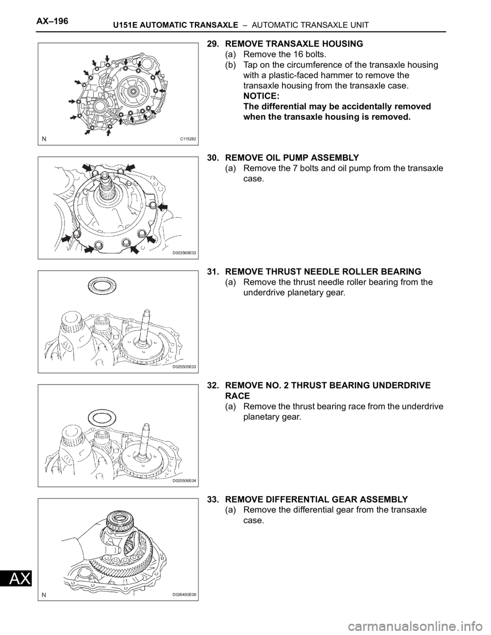
29. REMOVE TRANSAXLE HOUSING
(a) Remove the 16 bolts.
(b) Tap on the circumference of the transaxle housing
with a plastic-faced hammer to remove the
transaxle housing from the transaxle case.
NOTICE:
The differential may be accidentally removed
when the transaxle housing is removed.
30. REMOVE OIL PUMP ASSEMBLY
(a) Remove the 7 bolts and oil pump from the transaxle
case.
31. REMOVE THRUST NEEDLE ROLLER BEARING
(a) Remove the thrust needle roller bearing from the
underdrive planetary gear.
32. REMOVE NO. 2 THRUST BEARING UNDERDRIVE
RACE
(a) Remove the thrust bearing race from the underdrive
planetary gear.
33. REMOVE DIFFERENTIAL GEAR ASSEMBLY
(a) Remove the differential gear from the transaxle
case.
C115282
D003569E03
D025505E03
D025506E04
D026450E09
Page 1083 of 2000
U151E AUTOMATIC TRANSAXLE – AUTOMATIC TRANSAXLE UNITAX–209
AX
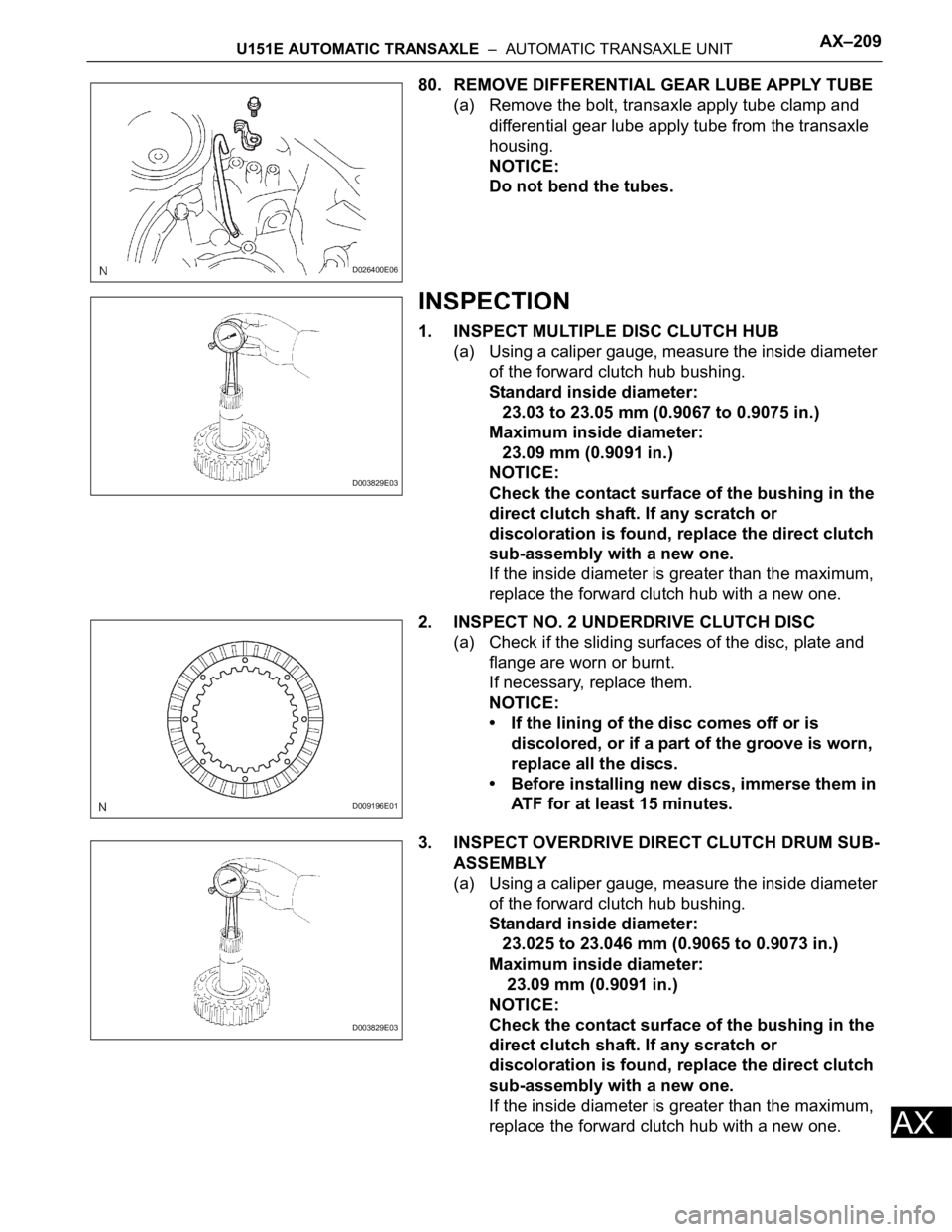
80. REMOVE DIFFERENTIAL GEAR LUBE APPLY TUBE
(a) Remove the bolt, transaxle apply tube clamp and
differential gear lube apply tube from the transaxle
housing.
NOTICE:
Do not bend the tubes.
INSPECTION
1. INSPECT MULTIPLE DISC CLUTCH HUB
(a) Using a caliper gauge, measure the inside diameter
of the forward clutch hub bushing.
Standard inside diameter:
23.03 to 23.05 mm (0.9067 to 0.9075 in.)
Maximum inside diameter:
23.09 mm (0.9091 in.)
NOTICE:
Check the contact surface of the bushing in the
direct clutch shaft. If any scratch or
discoloration is found, replace the direct clutch
sub-assembly with a new one.
If the inside diameter is greater than the maximum,
replace the forward clutch hub with a new one.
2. INSPECT NO. 2 UNDERDRIVE CLUTCH DISC
(a) Check if the sliding surfaces of the disc, plate and
flange are worn or burnt.
If necessary, replace them.
NOTICE:
• If the lining of the disc comes off or is
discolored, or if a part of the groove is worn,
replace all the discs.
• Before installing new discs, immerse them in
ATF for at least 15 minutes.
3. INSPECT OVERDRIVE DIRECT CLUTCH DRUM SUB-
ASSEMBLY
(a) Using a caliper gauge, measure the inside diameter
of the forward clutch hub bushing.
Standard inside diameter:
23.025 to 23.046 mm (0.9065 to 0.9073 in.)
Maximum inside diameter:
23.09 mm (0.9091 in.)
NOTICE:
Check the contact surface of the bushing in the
direct clutch shaft. If any scratch or
discoloration is found, replace the direct clutch
sub-assembly with a new one.
If the inside diameter is greater than the maximum,
replace the forward clutch hub with a new one.
D026400E06
D003829E03
D009196E01
D003829E03
Page 1088 of 2000
AX–214U151E AUTOMATIC TRANSAXLE – AUTOMATIC TRANSAXLE UNIT
AX
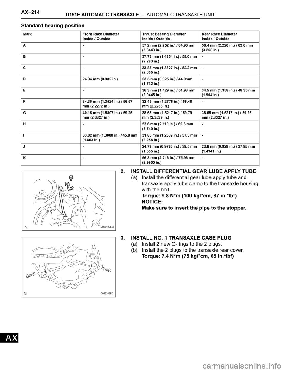
Standard bearing position
2. INSTALL DIFFERENTIAL GEAR LUBE APPLY TUBE
(a) Install the differential gear lube apply tube and
transaxle apply tube clamp to the transaxle housing
with the bolt.
Torque: 9.8 N*m (100 kgf*cm, 87 in.*lbf)
NOTICE:
Make sure to insert the pipe to the stopper.
3. INSTALL NO. 1 TRANSAXLE CASE PLUG
(a) Install 2 new O-rings to the 2 plugs.
(b) Install the 2 plugs to the transaxle rear cover.
Torque: 7.4 N*m (75 kgf*cm, 65 in.*lbf)
Mark Front Race Diameter
Inside / OutsideThrust Bearing Diameter
Inside / OutsideRear Race Diameter
Inside / Outside
A - 57.2 mm (2.252 in.) / 84.96 mm
(3.3449 in.)56.4 mm (2.220 in.) / 83.0 mm
(3.268 in.)
B - 37.73 mm (1.4854 in.) / 58.0 mm
(2.283 in.)-
C - 33.85 mm (1.3327 in.) / 52.2 mm
(2.055 in.)-
D 24.94 mm (0.982 in.) 23.5 mm (0.925 in.) / 44.0mm
(1.732 in.)-
E - 36.3 mm (1.429 in.) / 51.93 mm
(2.0445 in.)34.5 mm (1.358 in.) / 48.35 mm
(1.904 in.)
F 34.35 mm (1.3524 in.) / 56.57
mm (2.2272 in.)32.45 mm (1.2776 in.) / 56.48
mm (2.2236 in.)-
G 40.15 mm (1.5807 in.) / 59.25
mm (2.3327 in.)38.65 mm (1.5217 in.) / 59.79
mm (2.3539 in.)38.65 mm (1.5217 in.) / 59.25
mm (2.3327 in.)
H - 53.6 mm (2.110 in.) / 69.6 mm
(2.740 in.)-
I 33.02 mm (1.3000 in.) / 45.8 mm
(1.803 in.)31.85 mm (1.2539 in.) / 57.3 mm
(2.256 in.)-
J - 24.79 mm (0.9760 in.) / 39.5 mm
(1.555 in.)23.6 mm (0.929 in.) / 37.95 mm
(1.4941 in.)
K - 56.3 mm (2.216 in.) / 75.96 mm
(2.9905 in.)-
D026400E06
D026383E01